Abstract
This paper proposes a comprehensive framework for control of an extended Morphing Aerial System (MAS) designed to achieve both mission flexibility and fault tolerance. The proposed quadrotor features a morphing configuration that integrates a two-dimensional planar folding structure with a tilt mechanism. This morphing capability offers structural simplicity and operational versatility, which enables stable flight in various established modes. The control strategy utilizes feedback linearization and a Linear Quadratic Regulator (LQR), adapted to the system’s nonlinear dynamics and capable of controlling the MAS across various configurations (X, H, and O modes). An Extended Kalman Filter (EKF) is also incorporated for state estimation. To ensure fault resilience, we introduce the Y-mode configuration and a corresponding Fault-Tolerant Control (FTC) architecture. Numerical simulations demonstrate that while a nominal controller fails immediately upon motor failure, the proposed FTC method successfully recovers flight stability, converging to the reference trajectory within 6.9 s. Furthermore, robustness analysis confirms that the system maintains operational integrity for fault detection latencies up to 0.40 s, demonstrating its feasibility under realistic sensing constraints.
1. Introduction
With advances in quadrotor technology [1,2,3,4], this platform is now used for diverse missions in agriculture, security, transportation [5], and reconnaissance [6]. As real-world deployments expand, however, the associated limitations have become equally apparent. In challenging environments such as disaster areas [7], conventional quadrotors face significant risks of propeller interference due to obstacles. This vulnerability poses a substantial challenge for critical tasks like structural assessment and search-and-rescue. In these missions, traversing narrow openings or complex internal geometries is often essential for mission success. Employing mini-sized quadrotors can facilitate operation in tight spaces but at the cost of shorter endurance and limited payload capacity [8,9], thereby restricting the scope of feasible missions. These limitations have led to the emergence of Morphing Aerial Systems (MAS), a class of Unmanned Aerial Vehicles (UAVs) that can physically reshape to adapt to environmental complexity. By changing their configuration, MAS platforms can better manage in flight contingencies and energy consumption [10,11], and increase the usable workspace, particularly around the vehicle’s bottom region [12], thereby overcoming the physical constraints of fixed-frame quadrotors. Consequently, the enhanced physical adaptability and navigation resilience of MAS platforms have demonstrated higher success rates across diverse challenging missions compared to conventional aerial platforms.
Despite these advances, the fundamental challenge of navigating highly confined spaces, where the risk of propeller interference remains high, has not been fully resolved by all MAS. Methods that optimize the relative orientation of propellers [13] or employ tiltable rotors [14,15,16,17] improve controllability in hovering and expand manipulation degrees of freedom (DoF), but do not, by themselves, provide the geometry changes required to traverse confined spaces. Approaches based on actual frame reconfiguration [18,19,20,21], for example passive morphing [22], often rely on ballistic transit during transformation because flight stability degrades mid-morph, simplifying mechanics but hindering operation in cluttered environments due to the need for high initial speed. By contrast, planar folding platforms, such as the foldable quadrotor [23], provide various flight modes to pass narrow slots and vertical shafts, thereby broadening the mission set.
The first contribution of this paper is the proposal of an extended MAS modeling that accounts for the physical limitations of conventional fixed-frame quadrotors. It combines the planar folding strategy [23] to broaden the mission envelope and the tilting-rotor concept [24] to enable 6-Degree-of-Freedom (6-DOF) motion control. Unlike underactuated systems, this framework allows for independent control of position and attitude, significantly enhancing controllability and expanding the DoF of the workspace. The second contribution lies in the control design throughout configuration changes. While flight stability typically degrades mid-morph in passively reconfiguring systems, our proposed extended MAS utilizes a control strategy based on Linear Quadratic Regulator (LQR), that is dynamically adapted to the changing configuration. The third contribution is the development of a fault-tolerant [25] MAS architecture designed for high-assurance operation. As unforeseen disturbances, like crosswinds and gusts, can quickly escalate into catastrophic failures [26,27], the system must guarantee recoverability. Our architecture goes beyond hardware flexibility by proposing a mechanism that diagnoses motor failure scenarios in real time. It then executes autonomous reconfiguration to an appropriate morphology that preserves 6-DOF controllability despite the loss of actuation. This ensures that the system maintains full mission operational capability even after a motor failure, allowing for continued mission execution or safely initiating a return-to-base sequence. This strategy is essential for mitigating cascading failures and ensuring system recoverability in unpredictable, mission-critical environments.
The remainder of this paper is organized as follows. Section 2 describes the translational and rotational dynamics of the proposed MAS system. In Section 3, we introduce an adaptive control scheme that guarantees stable flight across morphologies and present a fault-detection method with the corresponding recovery maneuver for complete flight restoration. Section 4 shows numerical simulations to validate our control approach to proposing MAS.
2. Modeling of 8-Joint Morphing Drone
2.1. Morphing Mechanism Design
Morphing systems require a trade-off between design complexity and the diversity of achievable shapes. In particular, frames capable of three-dimensional morphing can convert into many configurations, but their mechanical complexity often yields heavy, unwieldy drones with shortened endurance and limited payload capacity. Avoiding kinematic singularities during morphing is also crucial, so as to prevent loss of controllability in flight. Accordingly, we propose a MAS that combines a rotating-joint and planar-folding architecture with tilt-enabled main rotors, thereby enabling diverse shape changes, while maintaining structural simplicity. Beyond this, tilt motors provide extra control authority and allocation redundancy, mitigating the risk of in flight loss of controllability. The overall structure of morphing drone is shown in Figure 1.
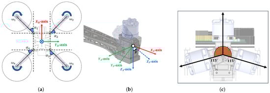
Figure 1.
(a) Body frame of morphing drone. (b) Tilt-rotor frame. (c) Maximum tilt angle.
The proposing MAS is designed consisting of three main subsystems. At its core is a central rigid body that houses the battery, onboard sensors, and control systems. Extending from this central body are four folding arms, each connected via a revolute joint. These arms allow for variable configuration, specifically through a horizontal flare angle, (). These angles are defined about the body axis and are actively controlled by servo motors embedded within the central body. Finally, tilt-rotor assemblies are mounted at the tips of each arm, carrying the main motors. Crucially, each of these tilt motors provides a variable tilt angle, (). This angle operates about the local axis of the arm and is actuated by dedicated servo motors positioned near the arm tips, which are mechanically constrained to operate within a range of . This combined folding and tilting mechanism enables the drone to actively reshape its configuration in flight.
While many mission-specific morphologies are possible, this work proposes four morphing modes as shown in Figure 2. The vehicle can transition in flight from the standard X-mode () to mission-specific morphologies. This capability enables a tunable trade-off between endurance and agility. In particular, the X-mode offers the most agile maneuvers, allowing for precise adjustment of the position and orientation of the workspace required for complex missions.
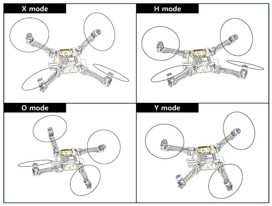
Figure 2.
Mission-Specific Configurations of Morphing Drone.
O-mode folds all arms in the same direction, greatly sacrificing efficiency and agility but enabling passage through narrow horizontal gaps. In H-mode, the front and rear arms are folded forward and backward, respectively. Also, this configuration isolates the propellers from the central interaction zone, significantly enhancing safety and facilitating physical tasks such as delivery or object manipulation. Additionally, adjusting the tilt-rotor angles not only helps the vehicle slip through tighter spaces but also expands the DoF of the workspace, maintaining manipulation capabilities even in this constrained morphology.
Finally, Y-mode addresses a loss of thrust from a main motor. When a failure occurs, the two arms adjacent to the failed motor are reoriented toward the failed side to recover balance. Subsequently, the tilt rotors provide yaw authority, enabling full reflight and stable continued operation. Crucially, the independent control of tilt angles in Y-mode allows for the maintenance of 6-DoF controllability, thereby expanding the workspace DoF to support full mission operations despite the failure. The validation of this capability is presented in the Numerical Simulation section.
2.2. Equations of Motion
The equations of motion are obtained by augmenting the standard quadrotor model [28] to include center of gravity (CoG) shifts, inertia variations, and force, torque terms induced by flare and tilt angle. We define the frame transformations using rotation matrices that are parameterized by the flare angles and tilt angles , as summarized in Table 1. All coordinate frames follow the north–east–down (NED) convention, as illustrated in Figure 1.

Table 1.
Definitions of Frames and Rotation Matrices.
2.2.1. Center of Gravity and Moment of Inertia
In conventional quadrotors, the CoG is typically assumed to coincide with the geometric center of the vehicle. However, this assumption no longer holds for a morphing drone because each arm angle can be adjusted independently. Consequently, both the CoG and the inertia tensor of the vehicle must be recomputed and updated whenever the configuration changes. To facilitate the dynamic analysis of the complete vehicle, we make a key assumption about the inertia tensor. We neglect the variations caused by the tilt-joint rotation and consider only the changes induced by the flare-joint rotation. Following this assumption, the CoG offset from the geometric center, , is computed as (1). Here, and denote the mass of the body and i-th arm, respectively, while and denote their corresponding CoG position vectors. Intuitively, as the flare angles change, the arm masses move around the body, and CoG is shifted away from the geometric center. This CoG motion is small in symmetric configurations (X, H, O modes), but becomes significant in asymmetric configurations such as the Y-mode.
The inertia tensor of the morphing drone is defined about flare joint angles and . First, inertia tensor of each arm and tilt rotors are obtained from the CAD model, and its tensor is rotated to align with the body frame using . Subsequently, the composite inertia is computed via the parallel–axis theorem as (2), where denotes the skew-symmetric matrix of the vector . And , denote the inertia tensor of body and i-th arm component.
The states that when the arms are flared outward, more mass is distributed farther from the CoG, which increases the corresponding moments of inertia. As a result, the same control torque will produce slower angular acceleration in configurations with larger arm extensions.
2.2.2. Translational and Rotational Motion
The translational equations of motion are given in the world frame as [28]. The position vector and velocity vector are expressed in the inertial NED frame .
The translational dynamics of the morphing drone is similar to a conventional quadrotor. However, the resultant body-frame force becomes a function of and . To model this force, we define the thrust and reaction torque of each propeller as acting at the origin of , and express them as quadratic functions of the rotor speed. The value of is determined by the rotation direction of the i-th propeller. Specifically, the first and third propellers, which rotate clockwise (CW) are assigned . And the second and fourth propellers rotate counterclockwise (CCW) are assigned .
The translational force acting on is formed by the thrust vectors generated in each and then expressed in via the inter-frame rotation matrices. The rotation from the propeller frame to is computed as . Mapping the thrust vectors generated in the propeller frames into via , the translational force in (3) can be written as follows:
The detailed expression of is provided in the Appendix A. Aerodynamic drag is assumed to be negligible. By substituting the result of (5) into (3), the translational equation of motion is represented as follows:
In the case of a standard quadrotor (with no morphing), reduces to a single thrust vector aligned with the body z-axis, so changing the rotor speeds only changes the total vertical force. In MAS system, when the arms are flared or tilted, the individual thrust directions are no longer parallel, and effectively acts as a configuration-dependent thrust mixing matrix that can generate lateral forces as well.
By modeling the gyroscopic effect as disturbances [28], the rotational equations of motion are obtained as (7). Here, represents the roll, pitch, and yaw angles. The rotation sequence follows the ZYX Euler angles convention in NED frame. denotes the angular velocity vector expressed in .
The total body-fixed frame torque, which drives the rotational motion, is decomposed into two components and . The torque component is generated by the thrust forces. It is calculated as the sum of the cross products between the thrust vector (represented in ) and the position vector from the CoG to each motor, denoted as . This position vector is defined as , where is the position vector from the center of the body frame to the i-th motor.
And the reaction torque produced by propellers, expressed in , is defined as . This total torque is the summation of the individual propeller reaction torques , after each is transformed from to .
The final rotational motion in is obtained by combining the torque arising from thrusts and the propeller reaction torques. This combined torque is expressed as the product of the body-torque mixing matrix , and the rotor angular speed . The specific expression of is provided by sum of and . And to consider changes in inertia tensor due to morph, we use the inertia tensor notation from (2).
2.3. Parameter Identification
The parameters of the morphing drone are summarized in Table 2. The moment of inertia terms were obtained using the built-in tools of Autodesk Inventor, and the thrust and reaction torque coefficients were measured experimentally with the motors intended for the actual morphing drone.
Table 2.
System Parameters.
The determination of the propeller model’s thrust and torque coefficients was conducted using a dedicated test setup. A precision load cell with a 1 kg range, connected to an Arduino via an HX711 module, was used to measure force readings as a function of the PWM signal. The main rotor used for these thrust and torque tests was a X2212 (KV 1400) BLDC motor equipped with an propeller.
For the thrust coefficient test, load cell measurements were recorded using a 10-bit PWM input. The resulting thrust-PWM relationship was then fitted with a quadratic regression model Figure 3, which yielded an RMS fitting error of 0.213. This model accurately reflects the cut-in behavior before thrust is produced and the increasing nonlinearity observed at higher rotor speeds. Since the desired quantity, the thrust coefficient , must be expressed with respect to the rotor angular speed rather than the PWM signal, we utilized the specified maximum RPM of X2212 to map the PWM input to the angular speed, thereby obtaining the thrust coefficient .
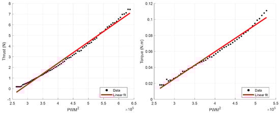
Figure 3.
Thrust and Moment Test Results.
Similarly, the reaction torque coefficient test utilized the force measurements obtained from the load cell. The applied torque was inferred using a simple lever mechanism with a known moment arm. The load-cell data driven by the 10-bit PWM input was fitted to a quadratic regression model Figure 3, which resulted in a notably low RMS fitting error of 0.00296. Applying the identical PWM-to-angular speed conversion used for the thrust test ensured the reaction-torque coefficient was properly expressed with respect to rotor angular speed, leading to the final coefficient value.
3. Controller Design
The controller for the proposed MAS is designed to manage the vehicle’s dynamic reconfigurability and ensure stability across diverse operating modes, including fault conditions. This section details the complete control architecture. First, we define the distinct operating modes utilized for mission flexibility and fault tolerance. Second, we present the feedback linearization strategy required to handle the large angular deflections inherent in morphing systems. Third, we describe the LQR controller employed for optimal control input synthesis. Finally, we detail the Extended Kalman Filter (EKF) designed for full-state estimation, which integrates sensor data into the control loop. The total control framework of the proposing MAS is illustrated in Figure 4.
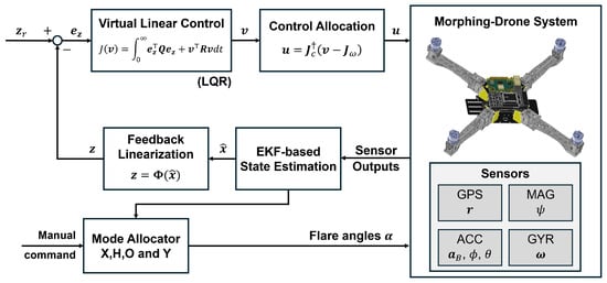
Figure 4.
Total Control Framework of MAS.
3.1. Mode Allocator Design
The proposing MAS controls a total of 12 actuators and can fly independently in each state. In contrast to conventional multi-rotors, which must tilt their attitude to generate forward translational motion, our platform can maintain a desired attitude while producing the required motion, and can adapt its morphology to diverse mission environments. The MAS utilizes several distinct operating morphologies to maximize mission success and ensure safety.
The baseline X-mode serves as the standard, highly stable configuration. In this mode, all flare angles are fixed to zero (, ), and the controller regulates only the tilt angles and the main-motor thrusts. For constrained environments, the vehicle employs two specialized modes. The H-mode is used for vertically constrained passages. This mode is achieved by setting the flare angles of arms and to and the angles of arms and to . The controller specifically accounts for the resulting changes in the center of gravity and the inertia tensor when maintaining stable flight in this configuration. The O-mode is deployed for horizontally constrained passages. This mode sets the flare angles of all four arms to (, ), and the controller incorporates the morphology-induced changes in vehicle dynamics to ensure stable operation.
If one main motor loses thrust or fails completely, the vehicle switches to Y-mode. Unlike many prior works that forgo yaw control in this fault case, our control architecture uses the remaining three main motors and their corresponding three tilt angles to retain full attitude authority. This capability is crucial for enabling fault-tolerant continued flight [29].
Although the controller linearization procedure is the same across modes, control allocation differs between the controllers that use four main motors (X, H, O) and those that use three main motors (Y). Focusing on this distinction, we design two classes of controllers: a four-main-motor set and a three-main-motor set.
3.2. Feedback Linearization
In both controllers, the flare angles are held fixed or pre-scheduled, and the tilt angles serve as the control input variables; hence a linearization with respect to the tilt angles is required. The tilt angles enter the dynamics through trigonometric terms. A basic approach would be a small-angle linearization that assumes infinitesimal variations in the tilt angle; however, the proposed morphing drone is expected to exhibit fast changes and large deflections in the tilt angle, making that approximation invalid. We therefore adopt a feedback-linearization strategy: by differentiating the full dynamics once to expose the tilt angular rate we obtain a linear input–output relation.
To treat the tilt angle as an input variable, we require an equation of motion that includes the tilt angle in the input vector in the form of . If we neglect the cross term of (10) as shown in the linearization process of [28] and combine with (6), the equation of motion can be expanded using null matrices as (11).
Note that the tilt angular rate is multiplied by the null matrix and cancels out. So this equation is an approximation to the equation of motion described in Section 2. However, by differentiating the full dynamics with respect to time, the terms associated with the tilt angles can be isolated and grouped with the input vector. To simplify this differentiation, we adopt the form presented in (12), which provides a Jacobian representation of (11), which are often used in feedback linearization process [24].
Differentiating the full equations of motion, expressed in the Jacobian form, with respect to time allows the terms associated with the tilt angles to be isolated and separated as the tilt angular rate, . Since the tiltflare angles are constant at their specific mode, their time derivatives vanish (). Furthermore, noting that , differentiation of (12) yields the following expression:
By rearranging the equations to collect the actuator inputs into a single vector, the system can be written so that the tilt angular rate effectively serves as a control input, as shown in (14).
We define the complete input vector as and substitude and as in (14). The system dynamics are subsequently linearized at the third-order derivative level. This is achieved by introducing a virtual control input and defining the output state as a new variables , composed of four derivatives, as follows:
As shown in (15), the dynamics can be recast into a linear state–space representation in the -domain. Accordingly, we synthesize the desired control input in this linear -domain and then map it back to the physical-domain input via the pseudo-inverse relationship when implementing the controller. Since Jacobians are a function of , , and MAS’s orientation, the controller take in account of the dynamic changes in morphing process, but because we assumed constant flare, angle the accuracy of dynamics under transitional phase decreases. However we demonstrate the validity of this assumption through experimental verification, leveraging the robustness of the controller.
3.3. Linear Quadratic Regulator Control
In the linearized -domain, we employ a LQR controller that determines the optimal control input by minimizing a quadratic cost in the state and control effort .
The cost function is defined as (17). Using the state and input , we solve the algebraic Riccati equation to obtain the optimal full-state feedback gain K. Because the Riccati equation generally lacks a closed-form solution, we compute K numerically using MATLAB R2025b built-in function. The resulting LQR control law in the -domain is , which serves as the virtual control input in the linear domain. Because (16) maps the virtual input back to the real control input, the effects of CoG shifts and moment-of-inertia changes are inherently accounted for in the transformation. Therefore, this control method is valid for the X, H, and O modes. We only need to schedule each flare angle accounting to the specific mission maneuver.
Y-mode is specifically designed for situations where one of the four main motors fails, enabling the vehicle to either safely return to base or continue mission execution with degraded performance. When a failure is detected in one of the four main motors, the flare angles are immediately adjusted to morph the airframe into the Y-mode (Figure 2). At this moment, the control system switches its operation from the nominal controller, which relies on four main motors and tilt angles, to the three main motor Fault Tolerant Controller (FTC), which uses only three main motors and tilt angles to regenerate the necessary control input .
The three main motor controller for the Y-mode is designed using the same procedure of linearization and LQR command synthesis. However, the state variations are faster under motor failure conditions, necessitating a more aggressive response. However, the state variations are faster under motor failure conditions, and the vehicle becomes more susceptible to instability due to the asymmetric thrust distribution caused by CoG shift. Therefore, the LQR weight matrix is adjusted to assign larger weights to the derivative states, and general scale of is increased compared to the nominal controller to enhance stability. Crucially, when converting the -domain control input to the real-domain input via (16), the rows and columns corresponding to the failed motor are removed from the transformation matrices before evaluation. This is necessary because the transformation matrix must reflect the physical reality of the system. When the failed motor speed is set to zero, the associated terms vanish and must be explicitly eliminated. Otherwise, the mixing logic would still allocate command through a motor that cannot generate thrust, leading to an immediate loss of control authority.
For successful reflight, the vehicle must first utilize reshaping to gain geometric advantage and then be stabilized by control. To this end, we perform an offline topology optimization to predetermine the optimal flare angles that enable stable reflight during the mission. Since the optimal configuration for a specific motor failure is constant for a given mass distribution, this problem is solved in advance. We defined a nonlinear topology optimization problem and obtained flare angles that minimize it. The topology optimization utilizes two distinct objectives.
- Minimize the distance between the thrust center and the center of gravity.
- Distribute the thrust of the remaining three motors uniformly in the plane.
In (18), the first term minimizes the distance between the configuration dependent , and the thrust center . The thrust center is defined as the centroid of the position vectors of the remaining three main motors, assuming these motors have identical performance. The second term aims to equalize the length of moment arms created by the remaining three motors. Here, represents the average length between the remaining motors and the thrust center. Each moment arm length is a function of the flare angles because the motor positions change with the morphing configuration. Utilizing the actual mass of the morphing drone and the position vectors of the motors, we employed MATLAB to solve the optimization problem offline and find the flare angles that minimize the two criteria above. For the case of Motor 1 failure, the optimal configuration yields a flare rotation of (, , , ). The resulting angle is larger than the perfectly symmetric found in typical tricopter designs because it effectively compensates for the asymmetric weight of the failed arm.
3.4. State Estimation
The controllers employed in the proposed morphing drone are based on full-state feedback. Therefore, all system states must be estimated. To estimate the 18 states, we designed an EKF [30] that fuses sensor measurements.
In practical application, sensors used in MAS are GPS, accelerometer, gyroscope, and magnetometer. From GPS data, we can measure position states in inertial frame (x, y, z). The accelerometer provides linear accelerations represented in (,,). Furthermore, by calculating the ratio of accelerometer measurements and gravitational acceleration, we can also obtain pseudo measurements of roll and pitch (). The gyroscope measures body frame angular rates (), and finally magnetometer provides heading angle (). Altogether these sensors yield 12-states of measurements.
To fully estimate all 18 states, we adopt the linearized -domain form of (15) as the EKF system model. As shown in (15), the vector is simply a reordering of the original states x meaning that no augmentation is applied. Accordingly, by incorporating the virtual control input into the prediction step, the state transition and input matrices (, ) used in the Kalman-filter prediction are given in (19). And the measurement matrix maps the 18-dimensional state to 12 measurements, as shown in (20).
Before each prediction step, the Kalman filter receives from controller and calculating process of via (15), replaces the Jacobian calculation of EKF. As shown in Figure 5, in the estimation phase of the EKF, the measurement function serves to extract the 12 states corresponding to the sensor outputs from the a priori state estimate, based on Equation (15). The measurement noise covariance matrix, , was determined according to the specifications of the sensors selected for the hardware platform: the ICM-20948 IMU and the RTK-GPS F9P Rover Lite. Meanwhile, the process noise covariance matrix was empirically tuned to to ensure stable and accurate estimation performance within the simulation environment [31]. The specific standard deviations constituting the measurement noise covariance are defined for each sensor component as follows: the accelerometer noise corresponds to , the Euler angle pseudo-measurement noise to , the gyroscope noise to , and the GPS position noise to . Rest of EKF prediction algorithm follows [30].
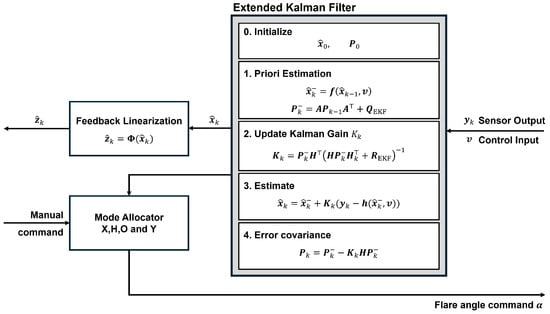
Figure 5.
EKF estimation process and Mode allocation.
4. Numerical Simulation
Numerical simulations were performed in the MATLAB environment to validate the performance and efficacy of the proposed overall control framework. The simulation campaign was divided into two main scenarios: nominal flight and fault-tolerant flight. The nominal flight scenario evaluated the performance of the X-, H-, and O-mode controllers under normal operating conditions. The fault-tolerant flight scenario assessed the Y-mode to maintain stable flight following a motor failure. The detailed simulation settings are summarized in Table 3.
Table 3.
Simulation Settings.
In the hardware design phase, we selected the XC430-W150-T and XC330-M288-T servo motors for flare and tilt adjustments, respectively. While these motors are capable of high actuation speeds, as detailed in Table 4, we modeled them conservatively as first-order lag systems with a 10 Hz cut-off frequency. Since the servo motor is typically the slowest component in the proposed MAS, this limitation underscores the imperative need for hardware-in-the-loop or flight tests to rigorously validate the control performance against the true physical constraints of the servo motors.
Table 4.
Servo Motor Specifications.
The first scenario, Figure 6 and Figure 7, validates the system’s performance by tracking specific position and attitude references while operating in the X-mode configuration. The position reference was set to (m), and the attitude reference was configured at degrees (deg), respectively. The LQR gain matrices and , defined in (17), are specified in Table 3. As confirmed in Figure 7, the X-mode maintains all flare angles fixed at . The results shown in Figure 6 demonstrate that the MAS system’s position response successfully converges. The maximum overshoot observed in the position response is (m). The attitude response also converges to the reference with a maximum overshoot of (deg). The total root mean square error (RMSE) for the position response is (m), and the RMSE for the attitude response is (deg). All the position and attitude responses converge within 15 s. The specific numerical values for overshoot and RMSE are summarized in Table 5 and Table 6.
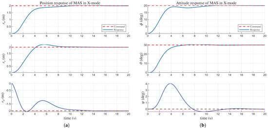
Figure 6.
(a) response in X-mode. (b) , , response in X-mode.
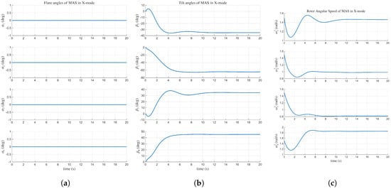
Figure 7.
(a) in X-mode. (b) in X-mode. (c) in X-mode.
Table 5.
Quantitative metrics of response in Simulation Scenarios.
Table 6.
Quantitative metrics of response in Simulation Scenarios.
The second scenario investigates the dynamic mode switching capability by tracking a position reference while the vehicle transitions immediately from the X-mode to the O-mode and then to the H-mode, shown in Figure 8. During these mode transitions, the flare angles are adjusted according to each mode’s definition, as illustrated in Figure 9. The prescribed flare angular rate was set to , enabling the MAS to complete the mode transition successfully in just 0.5 s. The results demonstrated robust performance in both specialized modes: the attitude response converged to in approximately 10 s, and the position response converged in approximately 5 s. The accompanying video [32] clearly shows the H-mode successfully traversing a confined space in the MATLAB simulation. The maximum overshoot observed in the position response in O-mode scenario is (m) and in H-mode scenario is (m). The attitude maximum overshoot in O-mode scenario is (deg) and in H-mode scenario is (deg). In the same vein, the specific numerical values of O-mode and H-mode scenarios are summarized in Table 5 and Table 6.
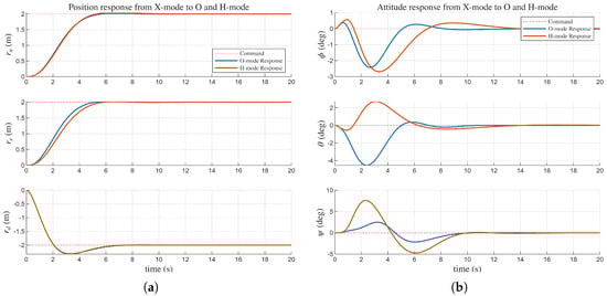
Figure 8.
(a) response in O and H-mode. (b) , , response in O and H-mode.
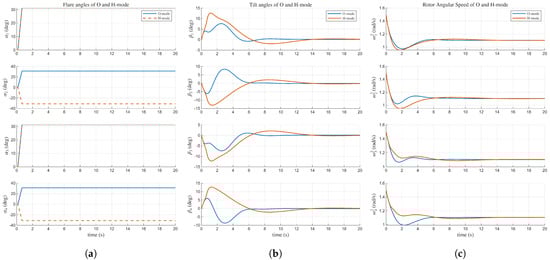
Figure 9.
(a) in O and H-mode. (b) in O and H-mode. (c) in O and H-mode.
The FTC validation scenario (Figure 10 and Figure 11) demonstrates the efficacy and performance of the proposed Y-mode configuration. As detailed in Table 3, a critical failure is induced in Motor 1 exactly at the 10-s mark of the simulation. This failure is modeled by having the squared motor speed linearly decrease to zero over a 1-s interval, leading to a complete loss of thrust from that motor.
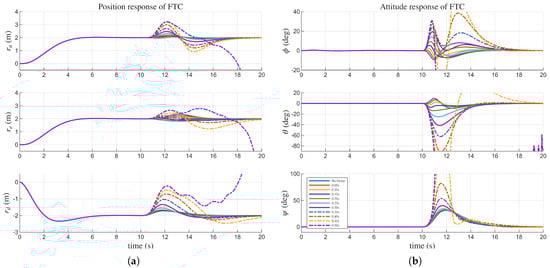
Figure 10.
FTC responses under varying fault detection time delays. (a) response in FTC. (b) response in FTC.
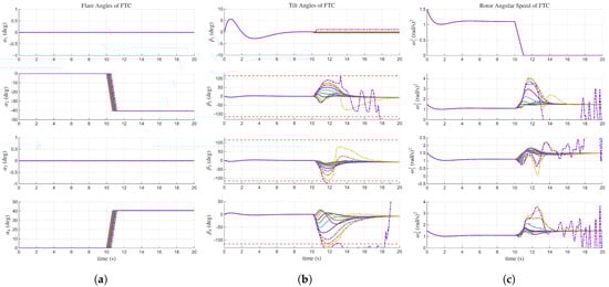
Figure 11.
FTC control inputs under varying fault detection time delays. (a) in FTC. (b) in FTC. (c) in FTC.
To validate the framework under realistic conditions, we conducted a parametric study by introducing time delays to the fault detection (FD) signal. These delays were selected based on realistic latency benchmarks derived from established FD algorithms [33,34,35], ranging from instantaneous detection to a conservative maximum of 0.50 s. Prior to the failure at , the vehicle maintains the stable X-mode. Following the specific delay interval after failure, the system switches to the FTC controller and simultaneously morphs into the Y-mode configuration.
As the detection delay increases in 0.05 s increments, the simulation results exhibit a progressive increase in overshoot for both position and attitude responses. Notably, Figure 11 reveals that the required tilt angles exceed the feasible mechanical limits when the delay surpasses 0.40 s. Consequently, the 0.50 s delay case, illustrated in Figure 10 and Figure 11 diverges after the failure event. However, the analysis underscores that rapid fault isolation is crucial; reducing detection time minimizes transient tilt angle excursions, thereby preventing the tilt mechanism from hitting its kinematic boundaries. This ensures that the FTC system operates within its linear region, maximizing control precision and significantly increasing the probability of successful mission continuation.
Additionally we conducted a robustness analysis of FTC by incorporating severe external disturbances. Specifically, we introduced combination of biased and stochastic angular acceleration [36,37] with constant bias of and superimposed with white noise having a standard deviation of . The simulation results, depicted in Figure 12 and Figure 13, demonstrate that despite the presence of significant disturbances, the FTC system maintains stability and successfully tracks the desired position and attitude references. The RMSE for position response under disturbance is (m) in position response and (deg) in attitude response. These findings underscore the robustness of the proposed FTC framework, highlighting its capability to effectively counteract external perturbations while ensuring reliable flight performance post-failure.
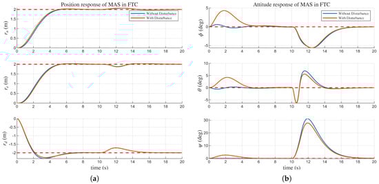
Figure 12.
Comparison of responses with and without external disturbances of the FTC scenario. (a) response in FTC. (b) response in FTC.
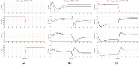
Figure 13.
Comparison of control inputs with and without external disturbances of the FTC scenario. (a) in FTC. (b) in FTC. (c) in FTC.
5. Discussion
The numerical simulation results successfully validate the stability and effectiveness of the proposed control framework across nominal (X, H, O) and fault-tolerant (Y) modes. However, the transition to physical deployment presents several key challenges, particularly concerning real-time FD and LQR optimization.
Robustness of the proposed framework was validated by introducing realistic time delays to the FD signal. The simulation results indicate that the system maintains stability for latencies up to 0.40 s. However, rapid FD is crucial; achieving a detection time significantly faster than this 0.40 s threshold is essential to minimize transient tilt excursions and prevent actuator saturation, thereby ensuring high-assurance recovery. To implement this in practice, a preceding layer of real-time fault diagnosis is required [33,34,35]. Furthermore, for successful hardware deployment, the process noise covariance must be fine-tuned experimentally to ensure accurate fault isolation in the presence of real-world sensor noise and disturbances [31].
Furthermore, the current feedback linearization strategy relies on simplifying assumptions that omit certain nonlinear terms and external disturbances, primarily in two areas. First, aerodynamic drag was assumed negligible due to the significant complexity of accurately modeling coupled forces during simultaneous propeller rotation and dynamic tilting. While this facilitates initial control design, it limits model fidelity, especially under large tilt angles. Second, the framework assumes zero flare angular velocity during configuration changes, thereby neglecting transient dynamics induced by arm motion. Although acceptable for slow morphing, this assumption may introduce unmodeled coupling effects during aggressive maneuvers. To collectively address these limitations, future research will incorporate adaptive control techniques or data-driven modeling methods utilizing hardware experimental data. This approach aims to effectively compensate for both aerodynamic drag and kinematic inaccuracies, ensuring robustness against unpredictable environmental factors and dynamic uncertainties.
In this study, the FTC performance was examined within a time window of approximately 0.3 s after the occurrence of a motor fault, during which the system remains inside the feasible region and the controller successfully recovers stable tracking. These results provide a useful baseline for future work on integrated fault detection and isolation, where early fault diagnosis will be combined with the proposed recovery strategy.
The LQR design relies on empirically determined weighting matrices ( and ) and will require careful retuning for practical hardware implementation due to unaccounted factors like sensor noise, actuator saturation, and joint flexibility. To bridge this gap between simulation and real-world implementation, future work will integrate the controller within a high-fidelity simulation environment using ROS2 and Gazebo [32,38] to build a realistic digital twin. Within this environment, we will employ systematic optimization methodologies—such as evolutionary algorithms or particle swarm optimization approaches—to determine LQR gains that maximize the robustness margin and minimize tracking error, explicitly considering hardware constraints.
6. Conclusions
This work presented a comprehensive framework for achieving fault-tolerant operation in a novel Morphing Quadrotor by developing both a reconfigurable platform and a fault-resilient control strategy. The platform features a two-dimensional planar folding structure with a tilt mechanism, enabling operational flexibility across X, H, and O configurations. Position and attitude tracking were established using a combined feedback linearization and LQR technique, augmented by an EKF for robust state estimation. Crucially, the novel Y-mode recovery configuration and its FTC architecture successfully retain yaw authority and recover flight stability following a single motor failure, enabling mission continuation or a return-to-base maneuver.
Author Contributions
Conceptualization, J.W. and I.J.; methodology, I.J.; software, J.W., I.J. and Y.K.; validation, J.W., I.J., Y.K. and S.L.; investigation, J.W., I.J. and Y.K.; resources, S.L.; data curation, J.W. and I.J.; writing—original draft preparation, J.W., I.J. and S.L.; writing—review and editing, J.W., I.J., Y.K. and S.L.; visualization, J.W., I.J. and Y.K.; supervision, S.L.; project administration, S.L.; funding acquisition, S.L. All authors have read and agreed to the published version of the manuscript.
Funding
This work was supported by the Chung-Ang University Research Grants in 2024 and by Ministry of Trade, Industry and Energy (MOTIE) and the Korea Institute for Advancement of Technology (KIAT), under the corporate demand-driven challenge and Innovative R&D Program for Next-Generation Researchers (Grant No.: RS-2025-16172970).
Data Availability Statement
The source code presented in this study is available on GitHub [38].
Conflicts of Interest
The authors declare no conflicts of interest.
Abbreviations
The following abbreviations are used in this manuscript:
| MAS | Morphing Aerial System |
| UAVs | Unmanned Aerial Vehicles |
| PWM | Pulse Width Modulation |
| RMS | Root Mean Square |
| LQR | Linear Quadratic Regulator |
| EKF | Extended Kalman Filter |
| GPS | Global Positioning System |
| FTC | Fault Tolerant Control |
| CoG | Center of Gravity |
| NED | North–East–Down |
Appendix A
The rotational transformation from , which follows the NED convention, to each is determined by a rotation about the z-axis of body frame. Specifically, the rotation angles for the four arm frames relative to the body frame , , , and , respectively. The full rotation matrix, , which transforms coordinates from the body frame to , can be obtained as:
The rotational transformation from to is determined by rotational matrix corresponding to each attitude angle of MAS.
The thrust magnitude is defined in as shown in (4). However, to express the system dynamics in , we must transform this thrust vector using the rotation matrix (A1). Therefore, the thrust vector in the body frame, , is given by the inverse rotation.
Finally, by summing and rearranging all four thrust vectors expressed in with respect to , the total resultant thrust vector force is expressed as follows:
To easily derive detailed form of the mixing matrix , we first derive it from MAS’s +frame. The + frame is defined to align motor arm 1 to north direction of NED frame by rotating −45 degree about z-axis from the original X-frame. The + frame representation is adopted because the rotation matrix from +frame to each propeller frame is simpler than X-frame to each propeller frame. After deriving the mixing matrix from +frame, we can convert it to X-frame by multiplying rotation matrix from +frame to X-frame, which is just −45 degree rotation about z-axis. Therefore, the mixing matrix from the original frame we used in Section 2 is as follows:
And in the same context, using and , the resultant external body torque, generated by the propeller thrust, is as follows:
Note that b is the distance from the center of body to arm joint, and l is the distance from arm joint to propeller center. Combining the Equations (2), (A2), (A5) and (A7) we can express the Jacobian representation used during the feedback linearization process as:
The Jacobian matrices above are expressed as function of flare angles and tilt angles, indicating control inputs created from Equation (16) will incorporate the changes in CoG, inertia, thrust, and torque due to morphing.
References
- Omar, H.M.; Mukras, S.M.S. Integrating anti-swing controller with px4 autopilot for quadrotor with suspended load. J. Mech. Sci. Technol. 2022, 36, 1511–1519. [Google Scholar] [CrossRef]
- Kangunde, V.; Jamisola, R.S., Jr.; Theophilus, E.K. A review on drones controlled in real-time. Int. J. Dyn. Control 2021, 9, 1832–1846. [Google Scholar] [CrossRef] [PubMed]
- Luppicini, R.; So, A. A technoethical review of commercial drone use in the context of governance, ethics, and privacy. Technol. Soc. 2016, 46, 109–119. [Google Scholar] [CrossRef]
- Peng, F.; Gao, Q.; Lu, H.; Bu, Z.; Jia, B.; Liu, G.; Tao, Z. Trajectory Tracking Control Method via Simulation for Quadrotor UAVs Based on Hierarchical Decision Dual-Threshold Adaptive Switching. Appl. Sci. 2025, 15, 11217. [Google Scholar] [CrossRef]
- Jafari-Shahbazzadeh, Z.; Binesh, A. Precision Landing Techniques for Drones: A Comprehensive Review. Iran. J. Sci. Technol. Trans. Mech. Eng. 2025, 1–28. [Google Scholar] [CrossRef]
- Wu, Y.-T.; Qin, Z.; Eizad, A.; Lyu, S.-K. Numerical investigation of the mechanical component design of a hexacopter drone for real-time fine dust monitoring. J. Mech. Sci. Technol. 2021, 35, 3101–3111. [Google Scholar] [CrossRef]
- Wang, Y.; Liu, C.; Zhang, K. A Novel Morphing Quadrotor UAV with Sarrus-Linkage-Based Reconfigurable Frame. In Proceedings of the 6th International Conference on Reconfigurable Mechanisms and Robots (ReMAR), Chicago, IL, USA, 23–26 June 2024. [Google Scholar]
- Riviere, V.; Manecy, A.; Viollet, S. Agile robotic fliers: A morphing-based approach. Soft Robot. 2018, 5, 541–553. [Google Scholar] [CrossRef]
- Tian, H.; Zhang, Z.; Zhou, Z.; Zhang, W.; Zhang, M.; Su, X. Design and optimization of self-foldable and self-deployable mechanism for portable drone arm. J. Mech. Sci. Technol. 2025, 1–15. [Google Scholar] [CrossRef]
- Derrouaoui, S.H.; Bouzid, Y.; Doula, A.; Boufroua, M.A.; Belmouhoub, A.; Guiatni, M.; Hamissi, A. Trajectory tracking control of a morphing UAV using radial basis function artificial neural network based fast terminal sliding mode: Theory and experimental. Aerosp. Sci. Technol. 2024, 155, 109719. [Google Scholar] [CrossRef]
- Rodrigue, H.; Cho, S.; Han, M.-W.; Bhandari, B.; Shim, J.-E.; Ahn, S.-H. Effect of twist morphing wing segment on aerodynamic performance of UAV. J. Mech. Sci. Technol. 2016, 30, 229–236. [Google Scholar] [CrossRef]
- Hamaza, S.; Kovac, M. Omni-drone: On the design of a novel aerial manipulator with omni-directional workspace. In Proceedings of the 17th International Conference on Ubiquitous Robots (UR), Kyoto, Japan, 22–26 June 2020. [Google Scholar]
- Brescianini, D.; D’Andrea, R. Design, modeling and control of an omni-directional aerial vehicle. In Proceedings of the IEEE International Conference on Robotics and Automation (ICRA), Stockholm, Sweden, 16–21 May 2016. [Google Scholar]
- Kamel, M.; Verling, S.; Elkhatib, O.; Sprecher, C.; Wulkop, P.; Taylor, Z.J.; Siegwart, R.; Gilitschenski, I. The voliro omniorientational hexacopter: An agile and maneuverable tiltable-rotor aerial vehicle. IEEE Robot. Autom. Mag. 2018, 25, 34–44. [Google Scholar] [CrossRef]
- Hwang, S.; Lee, D.; Kim, C.; Kim, H.J. Autonomous heavy object pushing using a coaxial tiltrotor. IEEE Trans. Autom. Sci. Eng. 2024, 22, 4243–4256. [Google Scholar] [CrossRef]
- Lee, D.; Kim, B.; Kim, H.J. Autonomous Aerial Manipulation at Arbitrary Pose in SE (3) with Robust Control and Whole-body Planning. arXiv 2025, arXiv:2508.19608. [Google Scholar]
- Zhao, M.; Anzai, T.; Shi, F.; Chen, X.; Okada, K.; Inaba, M. Design, modeling, and control of an aerial robot dragon: A dual-rotor-embedded multilink robot with the ability of multi-degree-of-freedom aerial transformation. IEEE Robot. Autom. Lett. 2018, 3, 1176–1183. [Google Scholar] [CrossRef]
- Hu, D.; Pei, Z.; Shi, J.; Tang, Z. Design, modeling and control of a novel morphing quadrotor. IEEE Robot. Autom. Lett. 2021, 6, 8013–8020. [Google Scholar] [CrossRef]
- Pastor, D.; Izraelevitz, J.; Nadan, P.; Bouman, A.; Burdick, J.; Kennedy, B. Design of a ballistically-launched foldable multirotor. In Proceedings of the IEEE/RSJ International Conference on Intelligent Robots and Systems (IROS), Macau, China, 3–8 November 2019. [Google Scholar]
- Wu, Z.; Huang, K.; Zhang, J. Modelling, Design, and Control of a Central Motor Driving Reconfigurable Quadcopter. Drones 2025, 9, 736. [Google Scholar] [CrossRef]
- Shehu, I.A.; Haruna, Z.; Mu’azu, M.B.; Abdurrazaq, M.B.; Wahab, N.A.; Umar, A. Robust Backstepping Sliding Mode Control for a Morphing Quadcopter UAV. In Proceedings of the 5th International Electronic Conference on Applied Sciences, Virtual, 4–6 December 2024. [Google Scholar]
- Bucki, N.; Mueller, M.W. Design and control of a passively morphing quadcopter. In Proceedings of the International Conference on Robotics and Automation (ICRA), Montreal, QC, Canada, 20–24 May 2019. [Google Scholar]
- Falanga, D.; Kleber, K.; Mintchev, S.; Floreano, D.; Scaramuzza, D. The foldable drone: A morphing quadrotor that can squeeze and fly. IEEE Robot. Autom. Lett. 2018, 4, 209–216. [Google Scholar] [CrossRef]
- Ryll, M.; Bulthoff, H.H.; Giordano, P.R. Modeling and control of a quadrotor UAV with tilting propellers. In Proceedings of the IEEE International Conference on Robotics and Automation, Saint Paul, MN, USA, 14–18 May 2012. [Google Scholar]
- Zhong, Y.; Chen, X.; Li, P.; Hou, P.; Wang, Z.; Nie, K. Active Fault-Tolerant Cooperative Control for Multi-QUAVs Using Relative Measurement Information. Drones 2025, 9, 699. [Google Scholar] [CrossRef]
- Yoon, J.; Kim, M.; Bang, J.; Kim, S.; Doh, J. Improvement of hovering stability for UAVs under crosswinds via evolutionary learning-based optimal PID control. J. Mech. Sci. Technol. 2025, 39, 2151–2162. [Google Scholar] [CrossRef]
- Kubacki, R.; Przesmycki, R.; Bugaj, M.; Laskowski, D. Investigation on Electromagnetic Immunity of Unmanned Aerial Vehicles in Electromagnetic Environment. Electronics 2025, 14, 4332. [Google Scholar] [CrossRef]
- Beard, R.W.; McLain, T.W. Small Unmanned Aircraft: Theory and Practice; Princeton University Press: Princeton, NJ, USA, 2012; pp. 28–39. [Google Scholar]
- Nan, F.; Sun, S.; Foehn, P.; Scaramuzza, D. Nonlinear MPC for quadrotor fault-tolerant control. IEEE Robot. Autom. Lett. 2022, 7, 5047–5054. [Google Scholar] [CrossRef]
- Baidya, B.; Mondal, A.; Manna, S.; Das, G.; Santra, A.; Chakraborty, A. Enhanced UAV Tracking through Multi-Sensor Fusion and Extended Kalman Filtering. In Proceedings of the Sixth Doctoral Symposium on Intelligence Enabled Research, Sukanta Mahavidyalaya, Dhupguri, India, 28–29 November 2024. [Google Scholar]
- Zarchan, P. Progress in Astronautics and Aeronautics: Fundamentals of Kalman Filtering: A Practical Approach; AIAA: Reston, VA, USA, 2005; Volume 208. [Google Scholar]
- Inyoung, J.; Jonghyun, W. Morphing Drone Failsafe Gazebo Simulation. Available online: https://www.youtube.com/watch?v=Sj3WPfR2m7s (accessed on 10 July 2025).
- van Schijndel, B.S.; Sun, S.; de Visser, C. Fast fault detection on a quadrotor using onboard sensors and a kalman filter approach. arXiv 2021, arXiv:2102.06439. [Google Scholar] [CrossRef]
- Li, Y.; Zhu, X.; Wang, F.; Wang, B.; Qi, R. Real-time actuator fault detection and isolation for quadrotor UAV via directional residuals. Meas. Sci. Technol. 2024, 36, 016227. [Google Scholar] [CrossRef]
- Li, H.; Jia, Q.; Ma, R.; Chen, X. Observer-based robust actuator fault isolation and identification for microsatellite attitude control systems. Aircr. Eng. Aerosp. Technol. 2021, 93, 1145–1155. [Google Scholar] [CrossRef]
- Sadiq, M.; Hayat, R.; Zeb, K.; Al-Durra, A.; Ullah, Z. Robust feedback linearization based disturbance observer control of quadrotor UAV. IEEE Access 2024, 12, 17966–17981. [Google Scholar] [CrossRef]
- Cai, Z.; Zhang, S.; Jing, X. Model predictive controller for quadcopter trajectory tracking based on feedback linearization. IEEE Access 2021, 9, 162909–162918. [Google Scholar] [CrossRef]
- Inyoung, J.; Jonghyun, W. Morphing-Drone. Available online: https://github.com/CAU-AISL/Morphing-Drone (accessed on 28 October 2025).
Disclaimer/Publisher’s Note: The statements, opinions and data contained in all publications are solely those of the individual author(s) and contributor(s) and not of MDPI and/or the editor(s). MDPI and/or the editor(s) disclaim responsibility for any injury to people or property resulting from any ideas, methods, instructions or products referred to in the content. |
© 2025 by the authors. Licensee MDPI, Basel, Switzerland. This article is an open access article distributed under the terms and conditions of the Creative Commons Attribution (CC BY) license.