Abstract
In response to the urgent need for performance predictions of damaged aerospace structures, this study undertakes a comprehensive investigation into the flutter characteristics of damaged variable-stiffness composite laminate (VSCL) plates. The governing boundary value problem for the dynamics of damaged VSCL plates is formulated using first-order shear deformation theory (FSDT). Additionally, the first-order piston theory is utilized to model the aerodynamic pressure in supersonic airflow. A novel coupling methodology is developed through the integration of penalty function methods and irregular mapping techniques, which effectively establishes the interaction between damaged and undamaged plate elements. The vibration characteristics and aeroelastic responses are systematically analyzed using the Chebyshev differential quadrature method (CDQM). The validity of the proposed model is thoroughly demonstrated through comparative analyses with the existing literature and finite element simulations, confirming its computational accuracy and broad applicability. A notable characteristic of this research is its ability to accommodate arbitrary geometric configurations within damaged regions. The numerical results unequivocally demonstrate that accurately predicting the flutter characteristics of damaged VSCL plates constitutes an effective strategy for mitigating structural stability degradation. This approach provides valuable insights for aerospace structural design and maintenance.
1. Introduction
The fiber-reinforced composite laminate is extensively utilized in aerospace, marine, automotive, and civil engineering applications due to its excellent properties [,,,,,]. Over the years, a significant portion of research has concentrated on composite laminates characterized by straight fibers. However, the ability to modify stiffness through the alteration of fiber orientation has considerably improved their mechanical properties []. Furthermore, with the continuous advancement of automated fiber placement technology, tailored fiber placement technology, and additive manufacturing technology, the manufacturing of variable-stiffness composite structures can be achieved efficiently and accurately [,]. Despite the numerous advantages that composite materials present in structural applications, they are also susceptible to a range of defects and damage. These include porosity, fiber matrix debonding, fiber breakage, and matrix micro-cracking [,,]. These defects will act as stress concentration points, disrupting the stress transmission between the fibers and the matrix, significantly reducing the material’s stiffness and strength, especially the interlaminar shear performance and fatigue life, and accelerating environmental aging. They often trigger and expand with each other, forming a damage network, and eventually lead to the premature failure of the structure under loads far below the theoretical value, seriously threatening safety and durability. Therefore, it is a novel and meaningful research to carry out dynamic analysis of variable-stiffness damaged structures with curvilinear fiber paths.
In recent years, VSCL plates have garnered significant attention from researchers []. Traditional finite element analysis (FEA) faces considerable computational challenges when developing models for variable-stiffness composite structures. This is primarily due to the need for discretizing curved fiber paths and providing sufficient degrees of freedom to ensure convergence and accuracy in calculations [,,,]. Hu et al. [] developed a strong form, meshless method that effectively simulates laminated cylindrical, conical, and fan-shaped structures with variable thickness and variable fiber curvature. The semi-analytical method [,,] has gained prominence as a widely adopted and efficient modeling approach, owing to its high accuracy and smooth continuity in fiber path modeling. Additionally, it requires a significantly lower degree of freedom compared to FEA. Thus, the computationally efficient semi-analytical method is employed for the dynamic modeling of variable-stiffness composite structures in this paper.
Subsequently, extensive research has been conducted by numerous scholars on variable-stiffness composite structures with curvilinear fiber paths. Through the analysis conducted using the Ritz method, Honda et al. [] demonstrated that quadratically shaped fiber composite plates exhibit superior local vibration performance compared to traditional straight-fiber configurations, particularly in terms of fundamental frequency characteristics. A novel analytical method was proposed by Honda and Narita [] to examine the free vibration behavior of fiber-reinforced composite plates with arbitrary fiber orientations. A layer-wise finite element approach considering von Karman’s non-linearity was employed by Houmat [] to analyze free vibration behavior in variable-stiffness laminated structures. Extending this research, Houmat [] performed optimization studies on laminate stacking sequences aimed at maximizing the fundamental frequency in variable-stiffness composite structures. Yan et al. [] proposed a novel quasi-3D solution approach to investigate free vibration characteristics of the VSCL plates with spatially varying fiber orientation angles. The accuracy of third-order shear deformation theory was systematically examined by Ribeiro et al. [] through free vibration analysis of plate structures across thin and thick VSCL plates. Venkatachari et al. [] developed a series of structural models utilizing a comprehensive methodology to assess the static response of curvilinear fiber-reinforced composite laminates.
The research discussed above primarily concentrates on intact composite laminate plates, neglecting the consideration of various defects and damages. However, these damages are expected to lead to a decrease in structural stiffness, which will ultimately impact the stability of the structure. Therefore, the rational modeling of damage is essential for investigating the dynamic response of the damaged composite material structures. Within the framework of continuum mechanics, Talreja [] developed a theoretical characterization method for damage vector fields. Valliappan et al. [] formulated a finite element numerical model by incorporating anisotropic damage constitutive relations, wherein damage parameters were defined along the principal orthogonal directions of composite laminates. Regarding the analysis of smart composite structures, Sreehari et al. [] employed a finite element approach based on inverse hyperbolic shear deformation theory to systematically investigate the bending and buckling mechanical behaviors of structures containing internal defects. Hirwani et al. [] conducted a further investigation into the transient dynamic response of delaminated composite laminates, taking into account geometric nonlinear effects. Through numerical simulations, Swain et al. [] revealed the significant impact of damage on the dynamic characteristics and aeroelastic behavior of carbon nanotube-reinforced functionally graded composite plates. These studies illustrate that anisotropic damage theory can effectively characterize the mechanical behavior of internal defects and damage present in composite laminated structures.
The existing literature predominantly investigates damage configurations with idealized geometric regularity, whereas real damage manifestations typically exhibit complex morphological irregularities. Therefore, a systematic investigation into the mechanical behavior of VSCL plates with irregularly shaped damage regions is of considerable engineering significance. To address this limitation, spectral element methods (SEMs) have emerged as an effective computational approach []. Specifically, Motlagh et al. [] employed SEM to partition the structural domain into geometrically continuous subregions. Within each subregion, the spectral Chebyshev technique was employed to compute local element matrices, which were subsequently assembled into a global system matrix through standard finite element procedures. The dynamic governing equations were then numerically solved to obtain the system response. Building upon this methodology, Zhong et al. [] proposed an advanced spectral element formulation that effectively addresses geometric discontinuities caused by holes and cracks in complex domains. This advanced spectral element framework demonstrated remarkable accuracy in predicting vibrational behavior of plates containing geometrically complex imperfections, including non-standard hole configurations and curvilinear crack paths.
Upon the discretization of the VSCL plate into multiple plate elements, it is essential to adequately address the continuity of displacements and the equilibrium of forces at the connected interfaces. The analysis of coupled structural systems employs several established techniques, including the stiffness matrix assembly approach [], artificial virtual spring technique [], and force–displacement equilibrium method []. Notably, Shao [] developed an advanced analytical framework that integrates simplified first-order shear deformation plate theory (S-FSDPT) with a virtual spring coupling mechanism for examining coupling plate structure. Ma et al. [] developed an effective interface coupling scheme that simultaneously satisfies kinematic continuity and dynamic equilibrium conditions, enabling coupling between deterministic plate elements and statistical energy analysis (SEA) subsystems. The artificial virtual spring coupling technology has become increasingly prevalent in the analysis of structural dynamics, primarily due to its computational efficiency in modeling intricate boundary coupling conditions. In the current investigation, this validated methodology is implemented to enable comprehensive prediction of spatially distributed dynamic responses throughout the plate domain.
Furthermore, a cohort of researchers has been consistently dedicated to investigating the aeroelastic behavior of the VSCL plate. Initial investigations conducted by Kuo [] provided a comprehensive characterization of the flutter velocity characteristics associated with variably spaced fiber composite laminates. Subsequently, Sharma et al. [] further advanced this research by systematically assessing the combined effects of fiber spacing patterns and material uncertainties on the aeroelastic performance of composite plates. Rahmanian et al. [] developed a nonlinear structural formulation based on the virtual work principle to systematically investigate the effects of varying fiber path functions on flutter velocity characteristics in VSCL cantilever plates. Rasool and Singha [] systematically investigated the instability characteristics and lamination parameter effects of constant/variable-stiffness composite plates under coupled mechanical–aerodynamic loading through finite element analysis and eigenvalue methods, while revealing the limit cycle oscillation phenomena in variable-stiffness plates. Fazilati and Khalafi [] developed a coupled isogeometric analysis–genetic algorithm framework to optimize the flutter performance of VSCL plates with linear fiber paths while elucidating the influence mechanisms of flow direction, boundary constraints, and layup characteristics on the optimization outcomes. Filippi and Carrera [] employed Carrera’s unified formulation to develop a computationally efficient, one-dimensional model for analyzing coupled bending-torsion flutter in thin-walled wings, validating the results against established theories and experimental data. An aeroelastic beam finite element model, incorporating Euler–Bernoulli theory and 2D unsteady aerodynamics, was developed to analyze wings with flexible control surfaces and validated against established numerical and literature results [].
As previously mentioned, the majority of studies on orthotropic anisotropic damaged plates are confined to rectangular regions. Moreover, there is a notable scarcity of research in the existing literature regarding VSCL plates with trapezoidal damage areas. This study investigates the vibrational behavior and aeroelastic dynamics of damaged VSCL plates, offering critical implications for real-world engineering design. The governing equations are formulated using FSDT in conjunction with Hamilton’s principle and piston theory. Additionally, boundary compatibility between adjacent plate elements is enforced via artificially introduced virtual coupling springs.
The structure of the remainder of this paper is as follows. In Section 2, the modeling process of the proposed semi-analytical method is explained in detail. A comparative validation of this method against results from other literature is presented to confirm its accuracy in Section 3. Additionally, the effects of various damage parameters, fiber orientations, and yaw angles on the vibrational response characteristics of damaged VSCL plates are investigated in Section 4. Finally, the aerodynamic response characteristics of damaged VSCL plates under different yaw angles and damage areas are examined in Section 4. The entire study is summarized with concluding remarks in Section 5.
2. Theoretical Formulations
This section presents the theoretical framework for a comprehensive flutter analysis program focused on damaged VSCL plates subjected to supersonic airflow based on FSDT and CDQM. The geometric and material configuration of the damaged VSCL plate is outlined in Section 2.1. In Section 2.2, the derivation of energy functionals for discrete plate elements is detailed, after which an orthotropic damage constitutive model is presented in Section 2.3. Geometric irregularities are addressed through a domain-coupling methodology proposed in Section 2.4 for improved solution fidelity. Finally, the spectral Chebyshev (ST) technique is introduced in Section 2.5 and Section 2.6, with its computational implementation included.
2.1. Model of Damaged VSCL Plate
A semi-analytical modeling approach for damaged VSCL plates within a unified framework is presented in this section. Figure 1 demonstrates a representative case of a VSCL plate. To improve model versatility for diverse engineering applications, the formulation incorporates artificial springs that can simulate various connection types and boundary conditions, including both linear and rotational constraints. With advancements in manufacturing technology, fiber orientation can now be defined as a function of x and y. In this study, the fiber orientation is assumed to vary linearly along the x-direction, transitioning from at the plate center to at a distance of Lx/2 from the plate origin. For curved fiber paths, the fiber orientation is denoted as <, >. The in-plane fiber orientation θ at any position x from the origin is mathematically expressed as
Figure 1.
Diagram of VSCL plates with an arbitrary damaged area.
2.2. Energy Functional Calculation
For the vibration analysis of damaged VSCL plates employing CDQM, the energy functional of each constituent plate element must first be derived. Following the principles of FSDT, the governing equations are formulated, enabling the displacement field associated with the i-th plate element to be represented in its local coordinate system as []
here, the mid-plane displacements along the three coordinate axes (x, y, z) are denoted by ui, vi, and wi, respectively, while rotational displacements about the y-axis and x-axis are characterized by parameters and correspondingly.
The planar surface is transformed into convex or concave structures through elastic deformation of local coordinates, which is induced by the application of periodic excitation at specific frequencies. This deformation is assumed to be continuous and reversible, with its magnitude being dependent on the excitation frequency.
The linear relationship between strain and displacement can be formulated in matrix notation as
where = [,,,,]T is the deformation vector, and is the strain vector.
For the k-th lamina of the damaged VSCL plate, the constitutive relationship between stress and strain can be formulated as
where the complete mathematical formulation of can be found in Ref. [].
Substituting Equation (3) into Equation (4) and integrating each component across the thickness of the damaged VSCL plate, the expression for the relationship between internal force and strain of the damaged VSCL plate can be obtained:
where represents the resultant stress, and the shear correction factor κ2 is 5/6 []. In addition, the superscript ‘0,i’ represents the strain of the middle layer of the i-th plate element.
The coefficients for individual plate elements are mathematically expressed as
The strain energy of the damaged VSCL plate can be expressed in its geometric domain as
Here, N denotes the total quantity of plate elements in the system.
The expression of kinetic energy is given as
where (, , ) indicates the principal moments of inertia per plate element.
It is worth noting that the vibration behavior of laminated structures is often accompanied by thermal effects. However, under certain specific working conditions, the heat generated is extremely small, and the temperature change can be ignored.
The pressure difference induced by aerodynamic effects on the VSCL plate takes the form []
The external work contribution from aerodynamic forces may be formulated as
The aerodynamic pressure in this study is defined as = /. The contribution from non-conservative forces takes the following form:
The kinematic compatibility at plate element interfaces and boundaries can be numerically represented, with the energy functional taking the form []
where , , and are the relative motion between adjoining boundary points. and represent relative rotation angles.
2.3. Damage Modeling
Following Valliappan et al. [], the damage is characterized using two distinct parameters: a1, representing damage along the fiber direction, and a2, accounting for damage perpendicular to the fiber orientation. These damage parameters are defined as follows:
Here, and represent the total cross-sectional area and the effective load-bearing area after damage, respectively. The stress and strain relationship for the damaged part of the VSCL plates is modified as
Here, is the damage coefficient matrix, which can be defined as
2.4. Irregular Domain Coupling Technology
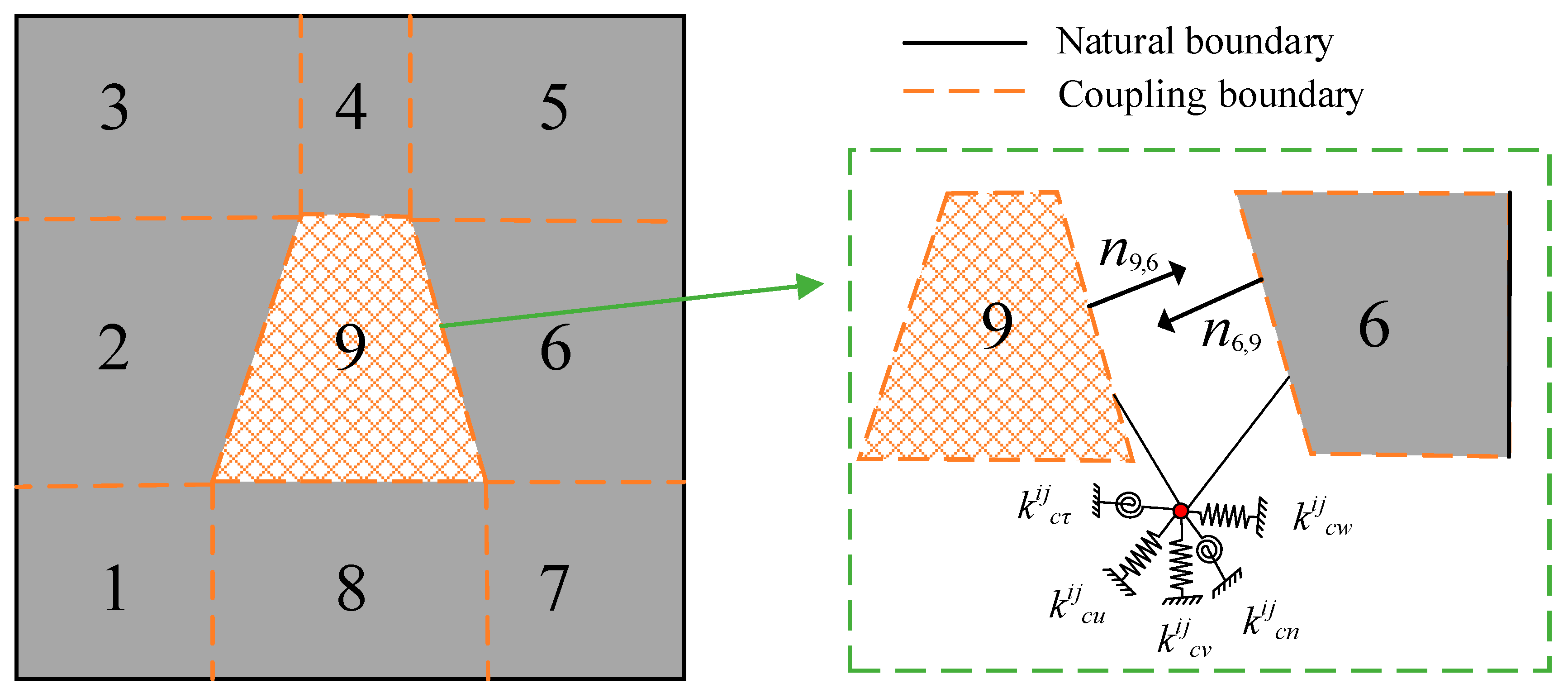
As shown in Figure 2, the damaged VSCL plate is divided into 9 plate elements along the damage boundary to distinguish the damaged area. Each pair of adjacent plate elements is connected by a coupling boundary, which is achieved through artificial virtual coupling springs. represents the external unit normal vector on the coupling boundary of the i-th plate element associated with the j-th plate element.
Figure 2.
The coupling process of the damaged VSCL plate elements.
The kinematic and kinetic compatibility conditions at plate element interfaces require consistent displacement and force relationships. The interfacial potential energy functional for coupled plates is formulated as []
where and denote the generalized nodal displacement vectors along the coupling interface, with = diag (,,,,) defining the diagonal matrix of interfacial spring parameters. The detailed expressions of and can be found in Ref. [].
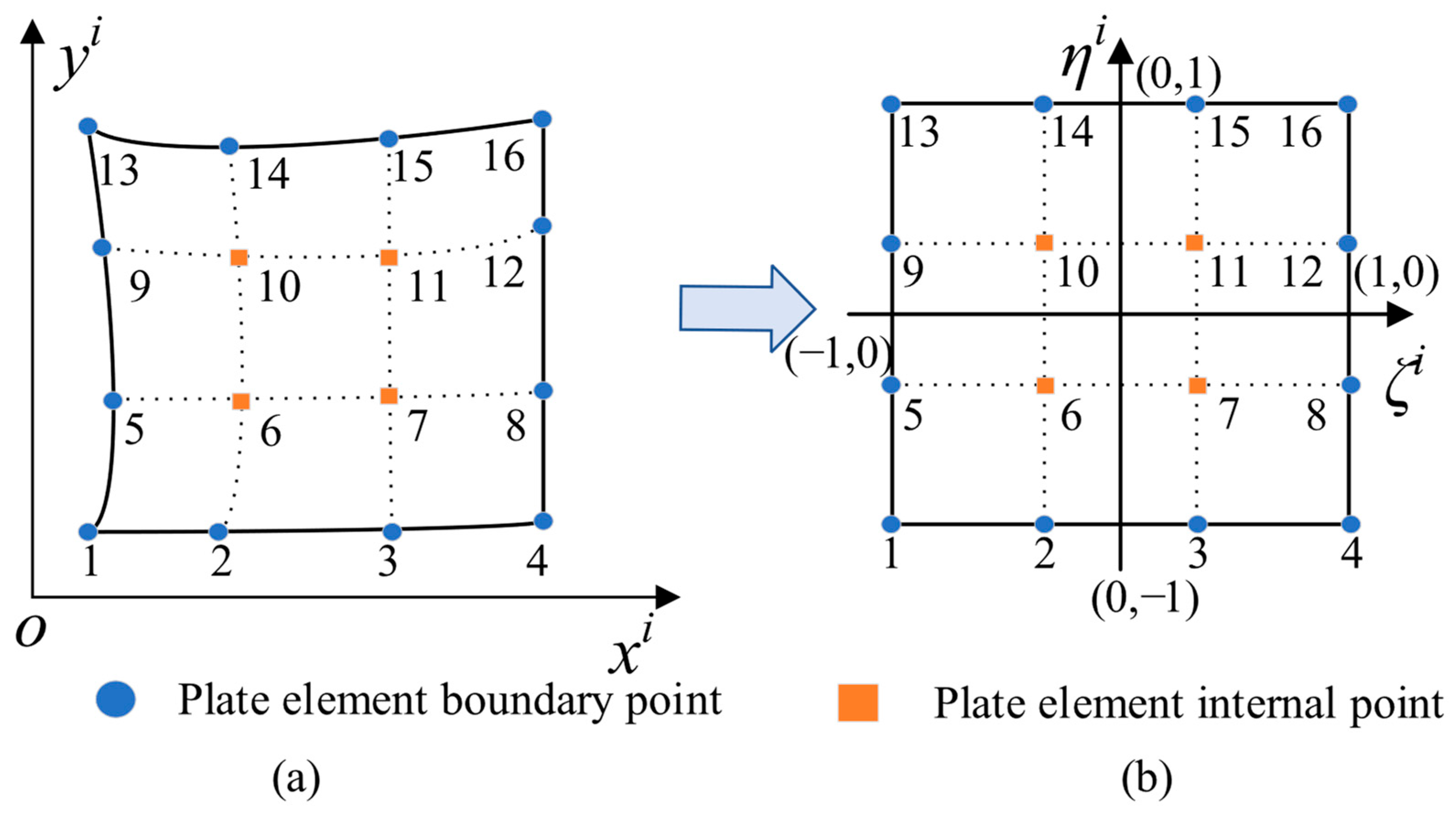
The strain and kinetic energy integration requires special treatment due to the geometrically complex domains arising from trapezoidal plate element discretization. As shown in Figure 3, the geometric mapping technique enables the transformation of trapezoidal plate elements into reference square elements for numerical integration. By utilizing this approach, the shape function can be articulated as follows
where and correspond to the local coordinates of the k-th nodal point within the i-th plate element’s reference frame. The variables m and n denote the number of mapping points utilized along the x-axis and y-axis, respectively, in this local coordinate system. Furthermore, Nk signifies the shape function corresponding to each mapping point, which is defined within the natural coordinate system.
Figure 3.
Irregular domain coordinate mapping: (a) The irregular domain in the local in-plane coordinate system. (b) The regular basic domain in the natural coordinate system.
The first-order partial derivative of in the natural coordinate system can be obtained by applying the relevant algorithms to the approximate mapping function, whose analytical expression takes the form
in which takes the form
2.5. Forced Vibration
The present work implements a numerical scheme integrating DQM with spectral polynomial bases. The defining recurrence relation for Chebyshev polynomials of the first kind is expressed as
Here, , and . The detailed expressions of the Chebyshev polynomials can be found in Ref. [].
For a computational domain spanning an irregular interval , the requisite variable mapping assumes the representation
The derivative and integral operations for a function can be expressed in terms of scalable Chebyshev polynomials = as []
where S = (l2−l1)/2.
Therefore, a binary function can be defined as []
where the spectral coefficients are denoted by Aij, while M and N represent the respective orders of polynomial truncation.
The Runge phenomenon is mitigated through the replacement of conventional sampling points with Gauss–Lobatto node distributions along both spatial dimensions.
The functional value f can be expressed in terms of the expansion coefficients through the following relation
where CB and CF are transformation matrices, and CBCF = I.
The p-th order partial derivative of the function can be spectrally approximated via Chebyshev polynomial expansion as follows
The coefficients b and A exhibit the following functional relationship:
Here, = [,,,,,,,,,,]T.
The mixed partial derivative of order (p,q) for a function can be represented in the form
The detailed expressions of the differential operator D and the partial differential matrix Q can be found in Ref. [].
For bivariate functions and defined on a uniform domain, their inner product admits the following mathematical representation:
in which V is the inner-product matrix [].
Then, the trilinear functional of three differentiable functions admits the integral representation []
where is the weighted inner product matrix with relation to the weighting function , which is a diagonal matrix of m·n × m·n (see Ref. []). The elements of are determined by the number of Chebyshev polynomials m and n, as well as the values of at the Gauss–Lobatto point.
Since the fiber angle θ is a function of x and y, the weight functions (k = 1, 2, 3) can be defined according to Equations (1) and (5) as
Thus, the corresponding weighted inner product matrices of them can be obtained as described in Equation (32), labeled , and .
The uniform Chebyshev polynomial is utilized to establish the displacement function of the damaged VSCL plates, which can be expressed as
in which = [,,,,]T are the coefficients of the displacement function. ω is the undamped circular frequency, and j represents the imaginary unit.
The energy function of the damaged VSCL plates is obtained by the Hamiltonian principle
The forced vibration equation of the damaged VSCL plate can be obtained
where the subscripts ‘u’ and ‘d’ represent undamaged and damaged plates, respectively. The complete mathematical formulations for , , , and are provided in Appendix A.
2.6. Flutter Solution
For solving the flutter problem of damaged VSCL plates, the governing system equation can be expressed in the following form:
The solution of Equation (37) is = + , where the real part () is the damping ratio, and the imaginary part () is the natural frequency of the VSCL plate in the aeroelastic environment. Flutter instability emerges when two structural modal frequencies coalesce under critical aerodynamic loading conditions. The critical flutter pressure λcr corresponds to the aerodynamic load at which the damaged VSCL plate first becomes unstable. The full expressions for the damping matrix and stiffness matrix are provided in Appendix A. To facilitate subsequent calculations, the damping ratio can be expressed as follows:
3. Result Verification
This section demonstrates the validation process for the proposed methodology. Three distinct test cases are systematically examined to evaluate the model’s predictive accuracy. This lays a foundation for further research on the response characteristics of structures in supersonic airflow.
To validate the proposed model, comparative analyses are conducted between the current model predictions, existing literature data, and finite element simulation results in this section. The validation study initially investigates two square VSCL plates featuring distinct laminated schemes: [<0°, 45°>, <−45°, −60°>, <0°, 45°>] and [<90°, 45°>, <60°,30°>, <90°, 45°>]. The plates feature planar dimensions of 1 m × 1 m with a uniform thickness of 10 mm. The mechanical properties of the VSCL plates are taken as E11 = 173 GPa, E22 = 7.2 GPa, G12 = G13 = G23 = 3.76 GPa, = 0.29, and ρ = 1540 kg/m3. The boundary constraints of the coupled model are represented by permutations of C (clamped), S (simply supported), and F (free). The virtual spring coefficient in this study is 1016 []. Table 1 and Table 2 present the comparison of the first eight natural frequency values of VSCL plates under two boundary conditions. A high degree of consistency is observed between the model predictions and published literature data [,]. As shown in Table 1 and Table 2, for the clamped plates, significant errors may occur in high-order modes, which might be due to the fact that the penalty function method is more sensitive to clamped boundaries. For free plates, the occurrence of significant errors in low-order modes might be accidental errors.
Table 1.
Natural frequencies [Hz] for the clamped VSCL plates.
Table 2.
Natural frequencies [Hz] for the free VSCL plates.
The damage model is subsequently validated through finite element analysis using COMSOL Multiphysics 6.1. The modeling of composite plates is conducted using solid elements, while it is also necessary to partition the plate into regions for the identification of damage areas. In the material properties of the damaged region, a reduced elastic modulus is input, whereas normal values are assigned to the material properties in the healthy region. The damaged plate maintains identical dimensions to those previously specified. A trapezoidal damage zone is implemented, which is defined by the following vertex coordinates: (−0.25,−0.25), (0.25,−0.25), (−0.15,0.25), and (0.15,0.25). The model proposed in this paper has no restrictions on the shape of the damaged area. Table 3, Table 4, Table 5 and Table 6 present the first eight natural frequencies and corresponding mode shapes for both laminated schemes under damaged conditions. Comparative results demonstrate excellent agreement between the proposed semi-analytical model and finite element simulations, with minimal numerical discrepancies. To calculate the steady-state response in COMSOL 6.1, damping is introduced in the form of a loss factor, which is set to 0.01. Additionally, a harmonic force directed along the z-axis (with an amplitude of 1 N) needs to be applied at the excitation point. It is important to note that in this paper, both the excitation point and the response point are located at the center of the plate. The steady-state responses of the damaged plates under two laminated schemes are illustrated in Figure 4. The results indicate that the current algorithm demonstrates a high level of agreement with the outcomes of finite element analysis.
Table 3.
The results of the first 8 natural frequencies of the undamaged and damaged plates obtained by the present method and the FEM. [0°/90°/0°], a1 = a2 = 0.2.
Table 4.
The results of the first 8 natural frequencies of the undamaged and damaged plates obtained by the present method and the FEM. [45°/90°/45°], a1 = a2 = 0.2.
Table 5.
The results of the modal shapes of the damaged plate obtained by the present method and the FEM. a1 = a2 = 0.2, SFSF, [0°/90°/0°].
Table 6.
The results of the modal shapes of the damaged plate obtained by the present method and the FEM. a1 = a2 = 0.2, SSSS, [45°/90°/45°].
Figure 4.
Results of the steady-state responses of the damaged plates under two laminated schemes. A1 = a2 = 0.2.
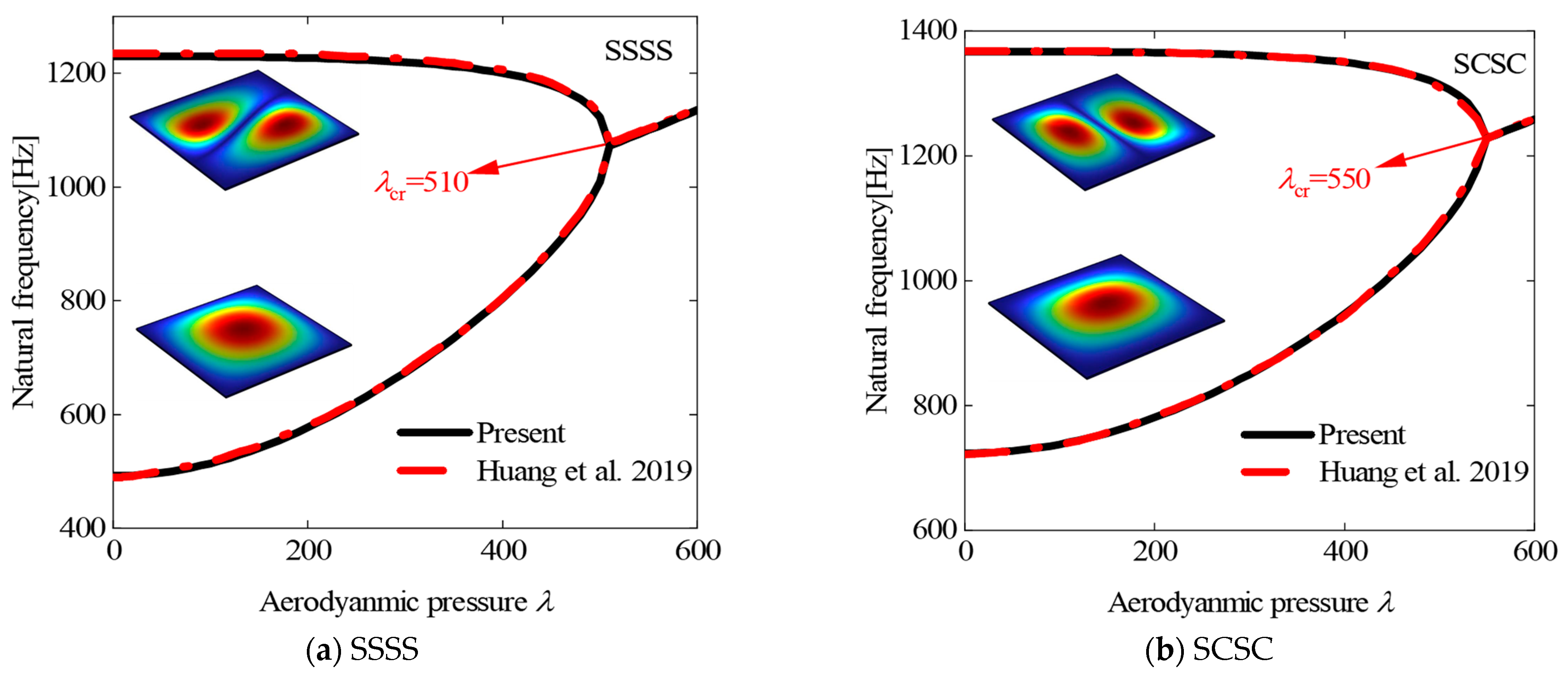
Finally, the free vibration characteristics of the panel structure under various aerodynamic pressures are systematically investigated. Figure 5 presents a comparative analysis between the frequency variation results of the rectangular panel obtained in this study and previously published data []. The investigation considered two distinct edge boundary conditions: simply supported (SSSS) and simply supported–clamped (SCSC) constraints. The fundamental material and geometric properties of the analyzed panels are collected as E = 210 Gpa, ν = 0.33, ρ = 7930 kg/m3, Lx = Ly = 0.1 m, and h = 0.001 m.
Figure 5.
The variations of the natural frequencies of plates in supersonic airflow with different aerodynamic pressures [].
4. Parametric Cases and Discussion
Subsequently, the free vibration characteristics of damaged VSCL plates under varying damage levels, damage orientations, and laminated schemes are demonstrated in Section 4.1. Subsequently, the effects of different damage levels, fiber orientations, and yaw angles on the flutter characteristics of damaged VSCL plates are analyzed in Section 4.2. Finally, the influence of various yaw angles and damage areas on damaged VSCL plates is investigated in Section 4.3.
4.1. Analysis of Free Vibration
This section investigates the influence of damage severity and orientation on free vibration characteristics under three boundary conditions for two distinct laminated schemes. The specific laminated schemes are [<0°, 45°>, <−45°, −60°>, <0°, 45°>] and [<90°, 45°>, <60°, 30°>, <90°, 45°>]. The analysis employs the same VSCL plate with a trapezoidal damage region as described in Section 3 (unless otherwise specified, this model will be consistently used throughout this study). The free vibration characteristics of the damaged VSCL plate with different values of a1 and a2, ranging from 0.1 to 0.6, are obtained and analyzed. The severity of damage can be predicted based on the values of the damage parameters (a1 and a2). The relative magnitude of these parameters also indicates the damage orientation: when a1 is significantly larger than a2, the damage direction tends to be nearly perpendicular to the fiber orientation, whereas when a2 dominates a1, the damage aligns predominantly parallel to the fibers. To systematically investigate the effects of damage severity and orientation, the damage parameters are assumed to vary within the range of 0.1 to 0.6.
First, the damage severity is set to be equal in both directions (i.e., a1 = a2). The natural frequencies obtained for different laminated schemes as the damage severity increases are presented in Table 7. A pronounced reduction in the structural stability of VSCL plates is observed as damage severity increases. Nevertheless, the stability degradation can be partially mitigated through boundary stiffness enhancement. In the subsequent analysis, one damage parameter is maintained constant while the other is systematically varied, with the corresponding results being presented in Table 8 and Table 9. It is found that the stability of VSCL plates is reduced by an increase in either damage parameter. Moreover, under identical conditions, less degradation of the fundamental frequency is exhibited when the damage direction is aligned parallel to the fiber orientation in comparison with other orientations.
Table 7.
Natural frequencies [Hz] of [<0°, 45°>, <−45°, −60°>, <0°, 45°>] and [<90°, 45°>, <60°, 30°>, <90°, 45°>] with respect to damage severity. a1 = a2.
Table 8.
Natural frequencies [Hz] of [<0°, 45°>, <−45°, −60°>, <0°, 45°>] and [<90°, 45°>, <60°, 30°>, <90°, 45°>] with respect to damage severity. a1 = 0.1.
Table 9.
Natural frequencies [Hz] of [<0°, 45°>, <−45°, −60°>, <0°, 45°>] and [<90°, 45°>, <60°, 30°>, <90°, 45°>] with respect to damage severity. a2 = 0.1.
4.2. Analysis of Flutter Boundary
Numerical simulations demonstrate that flutter instability in panel structures initiates when the first two natural frequencies coalesce under aerodynamic loading conditions. Given that structural integrity can be severely compromised by flutter phenomena, the accurate prediction of flutter characteristics for damaged VSCL plates is considered to be of significant engineering importance. Based on the findings presented in the preceding section, a further investigation is conducted in this study to examine how the flutter behavior of damaged VSCL plates is influenced by damage severity, fiber orientation, and yaw angle.
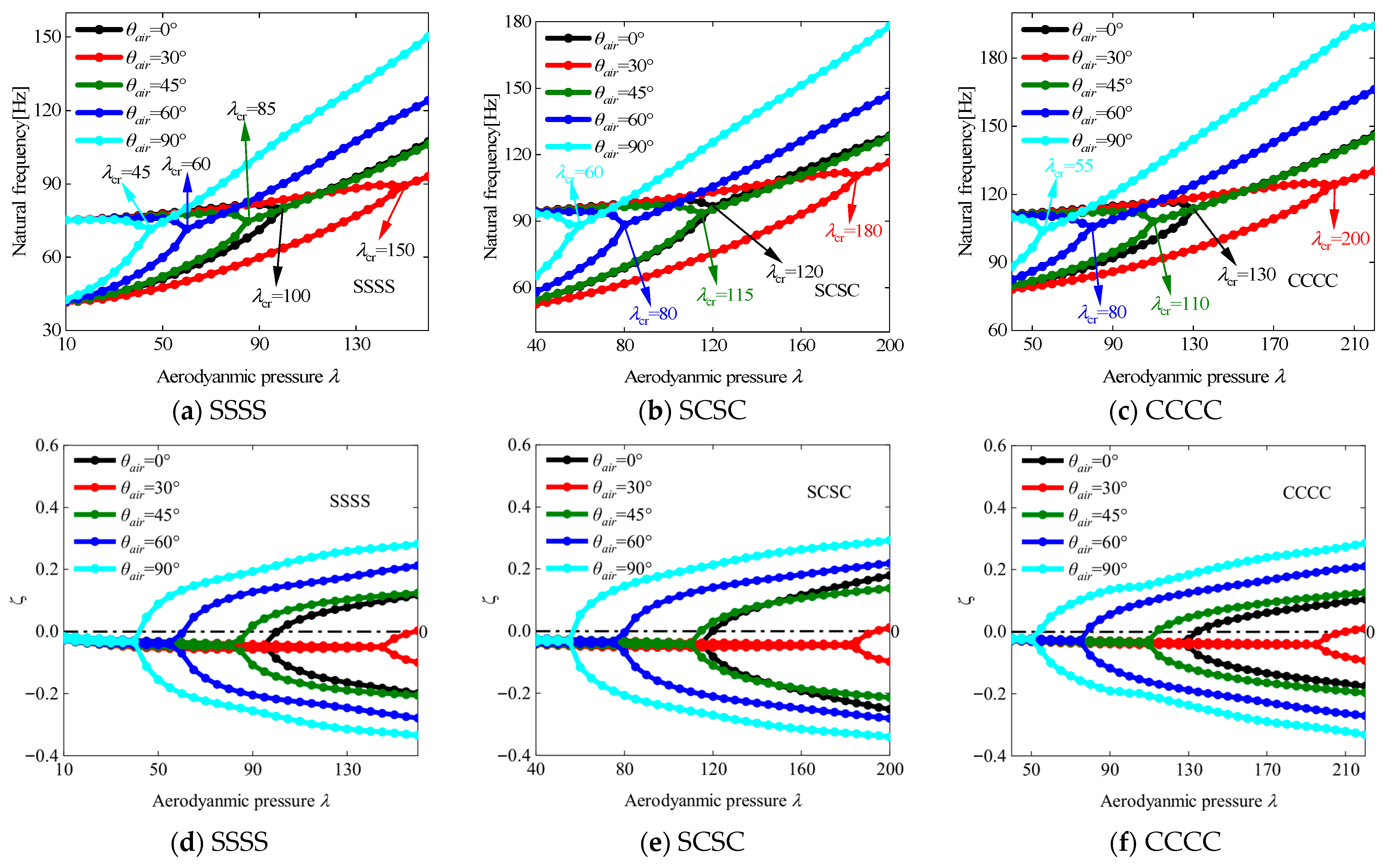
Figure 6 presents the flutter characteristics of VSCL plates with varying damage severity (a = a1 = a2) under three boundary conditions, with a yaw angle of 0° and the stacking sequence [<0°, 45°>, <−45°, −60°>, <0°, 45°>]. A progressive decrease in both flutter dynamic pressure and frequency is observed as damage severity increases. Notably, the boundary condition CCCC (fully clamped) provides higher flutter dynamic pressure relative to other configurations, attributable to its superior boundary stiffness. This enhancement can be attributed to the reduction in structural stability resulting from internal stiffness degradation caused by damage. Then, the flutter behavior corresponding to various laminated schemes is presented in Figure 7, with the damage severity being maintained at a1 = a2 = 0.2 and a yaw angle of 0°, while the laminated scheme is specified as [<θ, 45°>, <0°, 90°>, <45°, θ>]. From the analysis, it is observed that the flutter characteristics of damaged VSCL plates improve as the value of θ decreases. The observed performance enhancement is attributed to altered structural properties resulting from strategic fiber orientation adjustments within the laminate structure. Meanwhile, Figure 8 displays the flutter response under varying yaw angles θair for a constant damage level (a1 = a2 = 0.2) and laminated scheme [<0°, 45°>, <0°, 90°>, <45°, 0°>]. The investigation identifies the maximum flutter dynamic pressure at θair = 30°, while the minimum occurs at θair = 90°. This behavior suggests a strong correlation between aerodynamic loading direction and fiber orientation, where optimal flutter dynamic pressure is achieved at intermediate yaw angles.
Figure 6.
The relationships between the frequency and damping ratio of the VSCL plates and dimensionless aerodynamic pressure under various boundary conditions and different levels of damage. .
Figure 7.
The relationships between the frequency and damping ratio of the VSCL plates and dimensionless aerodynamic pressure under various boundary conditions and different fiber angles. .
Figure 8.
The relationships between the frequency and damping ratio of the VSCL plates and dimensionless aerodynamic pressure under various boundary conditions and different yaw angles. .
4.3. Analysis of Aeroelastic Response
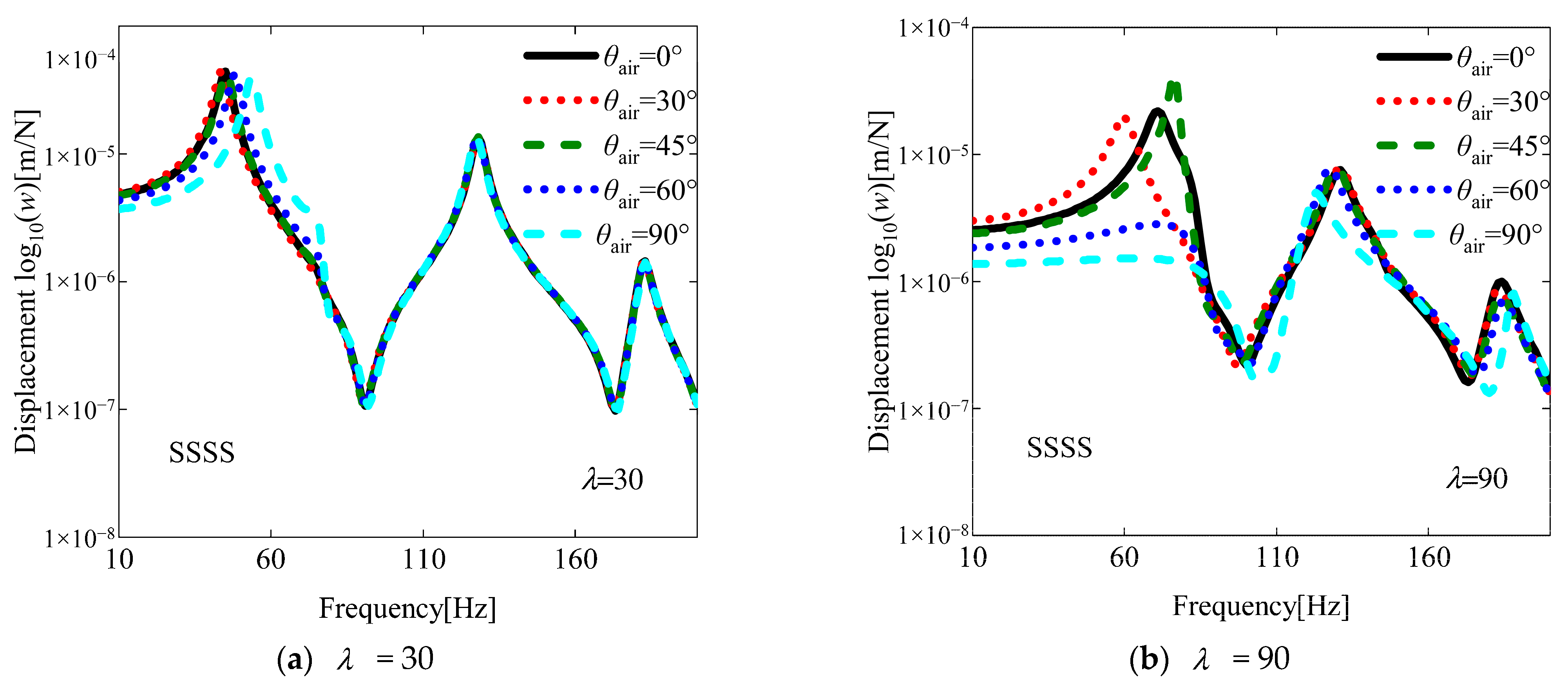
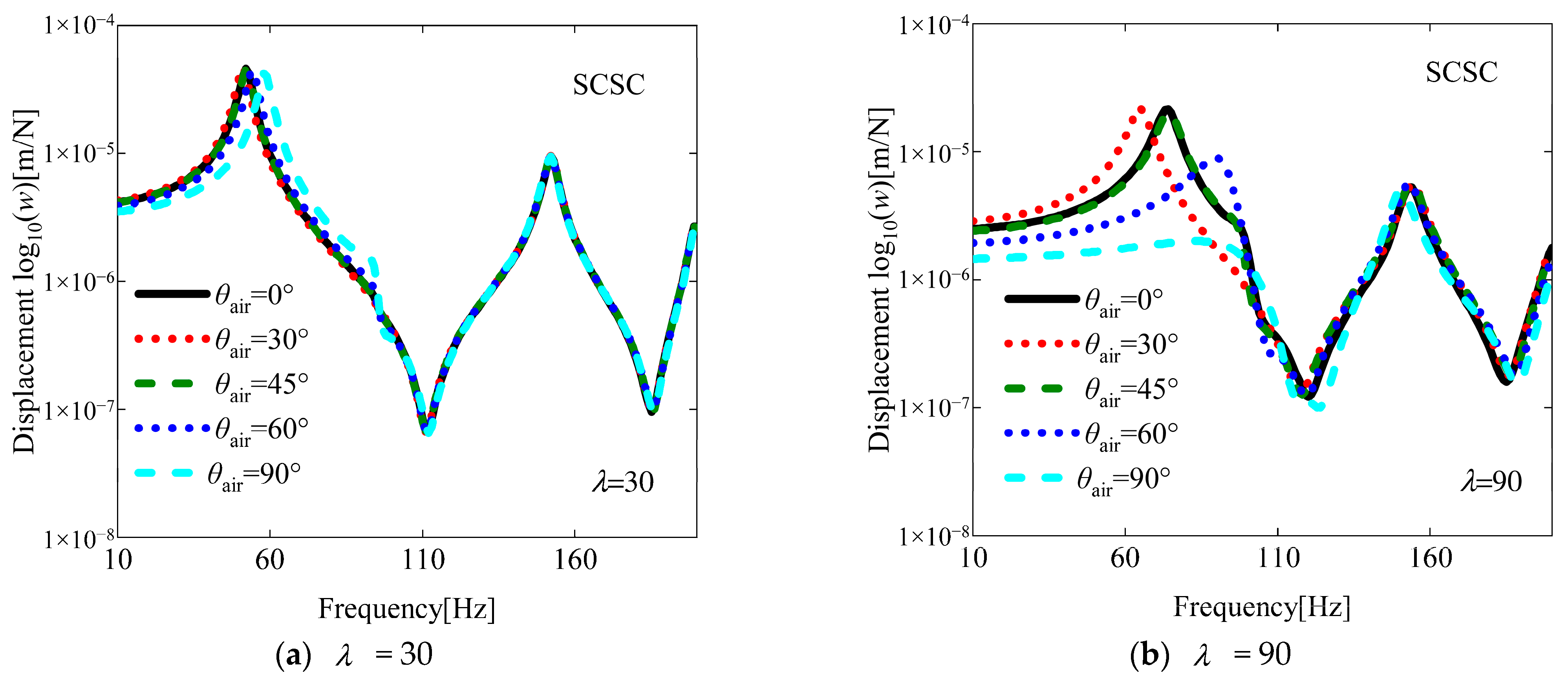
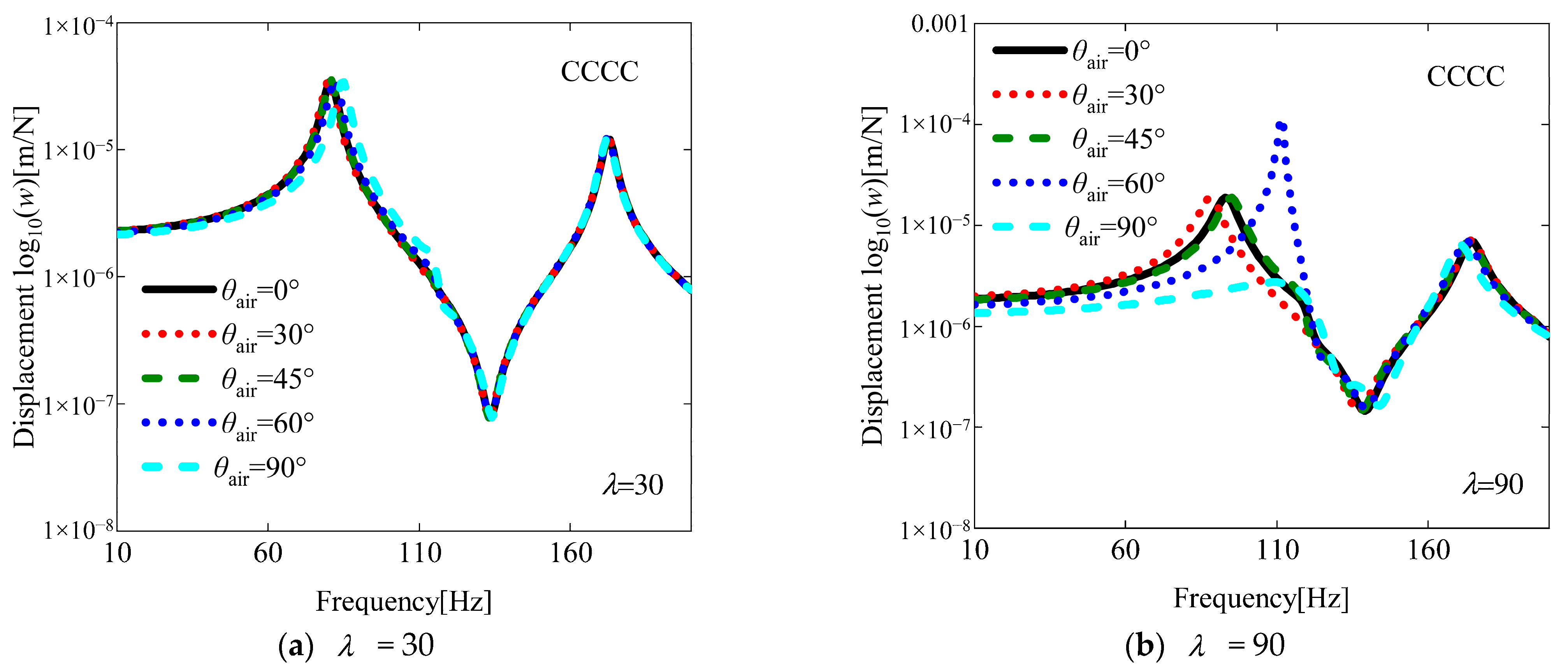
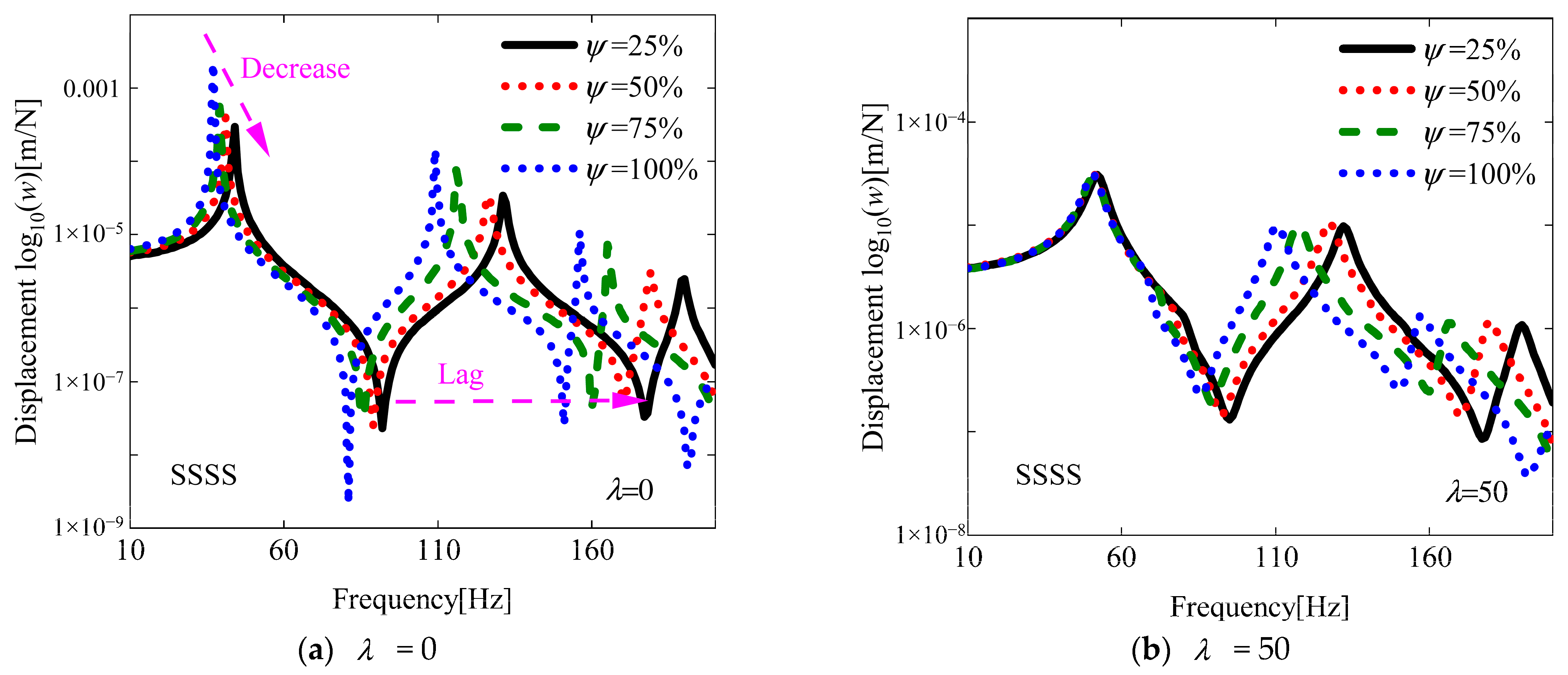
For a more comprehensive understanding of the flutter characteristics, an investigation of the aeroelastic response is conducted in this subsection, building upon previous research findings. As illustrated in the results presented in Figure 8, the aeroelastic responses at various yaw angles were investigated under two aerodynamic pressures of 30 and 90. The influence of varying yaw angles and damage areas on damaged VSCL plates is systematically examined. As shown in Figure 9, Figure 10 and Figure 11, the effects of different yaw angles are demonstrated under two distinct aerodynamic pressures. At an aerodynamic pressure of 30, only minor variations in displacement amplitude are observed in the fundamental frequency region. In contrast, when an aerodynamic pressure of 90 is applied, the maximum displacement amplitude is found to occur at a yaw angle of 45° under the boundary condition SSSS and 60° under the boundary condition CCCC. This phenomenon is attributed to the occurrence of flutter in the structure under this aerodynamic pressure (see Figure 8), which leads to a sudden decline in structural stability. Furthermore, near the fundamental frequency under the boundary condition SCSC, no maximum displacement amplitude is observed. This can be explained by the fact that when the aerodynamic pressure significantly exceeds the flutter pressure, the influence of aerodynamic damping becomes more pronounced. Subsequently, the influence of different damage areas on the aerodynamic response of the structure is investigated. The selected damage region is defined as a square domain, with the ratio of the side length L of the damaged area to the side length Lx of the plate referred to as the damage area ratio (i.e., Ψ =L/Lx). The effects of varying damage area ratios under two different aerodynamic pressures on the aerodynamic response of the damaged VSCL plate are illustrated in Figure 12, Figure 13 and Figure 14. As anticipated, it is observed that with a reduction in damage area, the displacement amplitude significantly decreased, and phase lag occurred. This indicates that an increase in damage area severely undermines the flutter stability of the structure.
Figure 9.
The aeroelastic responses of the SSSS VSCL plate under aerodynamic pressure, considering different yaw angles. [<0°, 45°>, <0°, 90°>, <45°, 0°>], a1 = a2 = 0.2.
Figure 10.
The aeroelastic responses of the SCSC VSCL plate under aerodynamic pressure, considering different yaw angles. [<0°, 45°>, <0°, 90°>, <45°, 0°>], a1 = a2 = 0.2.
Figure 11.
The aeroelastic responses of the CCCC VSCL plate under aerodynamic pressure, considering different yaw angles. [<0°,45°>, <0°,90°>, <45°,0°>], a1 = a2 = 0.2.
Figure 12.
The aeroelastic responses of the SSSS VSCL plate under aerodynamic pressure, considering different damage area ratios. [<0°, 45°>, <0°, 90°>, <45°, 0°>], a1 = a2 = 0.2, θair = 0°.
Figure 13.
The aeroelastic responses of the SCSC VSCL plate under aerodynamic pressure, considering different damage area ratios. [<0°, 45°>, <0°, 90°>, <45°, 0°>], a1 = a2 = 0.2, θair = 0°.
Figure 14.
The aeroelastic responses of the CCCC VSCL plate under aerodynamic pressure, considering different damage area ratios. [<0°, 45°>, <0°, 90°>, <45°, 0°>], a1 = a2 = 0.2, θair = 0°.
5. Conclusions
This study establishes a unified dynamic model for damaged VSCL plates by integrating FSDT with the CDQM. The vibrational behavior of these plates under supersonic aerodynamic loading is comprehensively examined. An innovative domain coupling methodology is developed to accurately simulate VSCL plates incorporating geometrically irregular damage areas. The predictive capability and practical utility of the developed dynamic model are demonstrated through rigorous comparative assessments, including eigenfrequency computation, modal parameter identification, steady-state performance evaluation, and flutter boundary analysis. The influence of various damage parameters and fiber orientations on the free vibration characteristics of damage VSCL plates is subsequently examined. Furthermore, flutter characteristics are investigated under different combinations of damage parameters, fiber orientations, and yaw angles. Finally, a systematic discussion is presented concerning the effects of yaw angle and damage area on the aeroelastic response of damage VSCL plates. The principal conclusions are summarized as follows:
- (1)
- A pronounced inverse relationship is observed between damage severity parameters (a1 and a2) and structural stability, manifesting as coordinated degradation of vibrational characteristics (natural frequencies) and aeroelastic performance (flutter boundaries) with increasing damage magnitude. Damage orientation relative to fiber direction critically influences vibration response, with damage parallel to fiber orientation exhibiting better stability compared to perpendicular damage cases;
- (2)
- Boundary conditions substantially affect damage tolerance, with the fully clamped (CCCC) configuration showing superior stability preservation due to enhanced constraint stiffness;
- (3)
- Optimal flutter dynamic pressure is achieved at the yaw angle θair = 30°, while minimum flutter dynamic pressure occurs at θair = 90°, indicating significant directional sensitivity. Fiber orientation angle θ plays a crucial role in modifying flutter boundaries through its influence on stiffness redistribution within the laminate structure;
- (4)
- The damage area ratio Ψ exhibits an inverse correlation with flutter stability, indicating that an increase in the damage area results in a substantial decrease in critical flutter conditions. The effects of aerodynamic damping become increasingly pronounced when the applied aerodynamic pressure significantly surpasses the critical flutter pressure. Maximum displacement amplitudes consistently manifest at the onset of flutter and exhibit characteristic variations depending on different boundary constraint configurations.
At present, some scholars have studied the potential application of machine learning technology in the prediction of fin flutter in composite material missiles []. Therefore, the application of machine learning technology in the flutter prediction of damaged composite material plates can be studied in the future.
Author Contributions
Conceptualization, P.Z. and D.S.; Methodology, P.Z., N.S. and D.S.; Software, P.Z.; Validation, P.Z.; Formal Analysis, P.Z. and N.S.; Investigation, P.Z. and N.S.; Resources, D.S.; Data Curation, P.Z. and D.S.; Writing—Original Draft Preparation, P.Z.; Writing—Review and Editing, D.S. and W.L.; Visualization, P.Z.; Supervision, D.S. and N.S.; Project Administration, D.S.; Funding Acquisition, D.S. and W.L. All authors have read and agreed to the published version of the manuscript.
Funding
This work was funded by the National Natural Science Foundation of China (Grant No. 52275076 and 51905511) and the Young Elite Scientist Sponsorship Program by CAST (Grant No. YESS20230554).
Institutional Review Board Statement
Not applicable.
Informed Consent Statement
Not applicable.
Data Availability Statement
The original contributions presented in this study are included in the article. Further inquiries can be directed to the corresponding author.
Acknowledgments
The authors would like to thank the anonymous reviewers for their very valuable comments. The authors also gratefully acknowledge the financial support from the National Natural Science Foundation of China (Grant No. 52275076 and 51905511) and the Young Elite Scientist Sponsorship Program by CAST (Grant No. YESS20230554).
Conflicts of Interest
The authors declare no conflicts of interest.
Nomenclature
| Ω | damage region | B | partial differential matrix |
| Lx | length | off-axis stiffness coefficient | |
| Ly | width | density of the plate | |
| h | thickness | air density | |
| θair | yaw angle | Mach number | |
| U∞ | airflow velocity | natural boundary | |
| F | excitation force | coupling boundary | |
| generalized mass matrix | generalized stiffness matrix | ||
| damping matrix |
Appendix A
Based on the theory mentioned in this paper, the system mass matrix can be derived as follows:
Through variational principles, the plate element’s stiffness matrix takes the form
It should be noted here that the stiffness coefficient substituted into the damaged plate element needs to be solved through Equation (16).
The dissipative properties of the system are characterized by the damping matrix
in the damping matrix can be written as
References
- Morangueira, Y.L.A.; Pereira, J.C.D. Energy harvesting assessment with a coupled full car and piezoelectric model. Energy 2020, 210, 118668. [Google Scholar] [CrossRef]
- Zhao, T.; Xu, M.; Xiao, X.; Ma, Y.; Li, Z.; Wang, Z.L. Recent progress in blue energy harvesting for powering distributed sensors in ocean. Nano Energy 2021, 88, 106199. [Google Scholar] [CrossRef]
- Dudem, B.; Kim, D.H.; Bharat, L.K.; Yu, J.S. Highly-flexible piezoelectric nanogenerators with silver nanowires and barium titanate embedded composite films for mechanical energy harvesting. Appl. Energy 2018, 230, 865–874. [Google Scholar] [CrossRef]
- Eugeni, M.; Elahi, H.; Fune, F.; Lampani, L.; Mastroddi, F.; Romano, G.P.; Gaudenzi, P. Numerical and experimental investigation of piezoelectric energy harvester based on flag-flutter. Aerosp. Sci. Technol. 2020, 97, 105634. [Google Scholar] [CrossRef]
- Elahi, H. The investigation on structural health monitoring of aerospace structures via piezoelectric aeroelastic energy harvesting. Microsyst. Technol. 2020, 27, 2605–2613. [Google Scholar] [CrossRef]
- Ucar, H. Patch-based piezoelectric energy harvesting on a marine boat exposed to wave-induced loads. Ocean. Eng. 2021, 236, 109568. [Google Scholar] [CrossRef]
- Ribeiro, P.; Akhavan, H.; Teter, A.; Warminski, J. A review on the mechanical behaviour of curvilinear fibre composite laminated panels. J. Compos. Mater. 2014, 48, 2761–2777. [Google Scholar] [CrossRef]
- Punera, D.; Mukherjee, P. Recent developments in manufacturing, mechanics, and design optimization of variable stiffness composites. J. Reinf. Plast. Comp. 2022, 41, 917–945. [Google Scholar] [CrossRef]
- Kim, B.C.; Potter, K.; Weaver, P.M. Continuous tow shearing for manufacturing variable angle tow composites. Compos. Part A Appl. Sci. Manuf. 2012, 43, 1347–1356. [Google Scholar] [CrossRef]
- Sharma, N.; Swain, P.K.; Maiti, D.K.; Singh, B.N. Vibration and Uncertainty Analysis of Functionally Graded Sandwich Plate Using Layerwise Theory. Aiaa J. 2022, 60, 3402–3423. [Google Scholar] [CrossRef]
- Salehi, M.; Gholami, R.; Ansari, R. Analytical solution approach for nonlinear vibration of shear deformable imperfect FG-GPLR porous nanocomposite cylindrical shells. Mech. Based Des. Struct. Mach. 2023, 51, 2177–2199. [Google Scholar] [CrossRef]
- Sharma, N.; Tiwari, P.; Maiti, D.K.; Maity, D. Free vibration analysis of functionally graded porous plate using 3-D degenerated shell element. Compos. Part C Open Access 2021, 6, 100208. [Google Scholar] [CrossRef]
- Jing, Z.; Duan, L.; Wang, S.Q.; Li, B. Buckling optimization of variable-stiffness composite plates via variable stiffness optimization algorithm. Compos. Struct. 2024, 327, 117657. [Google Scholar] [CrossRef]
- Sharma, N.; Swain, P.K.; Maiti, D.K.; Singh, B.N. Stochastic frequency analysis of laminated composite plate with curvilinear fiber. Mech. Adv. Mater. Struct. 2022, 29, 933–948. [Google Scholar] [CrossRef]
- Gao, Y.H.; Duan, J.B.; Lei, Y.J.; Xu, B.Q. Aerothermoelastic analysis of curvilinear fiber variable stiffness laminated panels in supersonic flow. Acta Mech. 2022, 233, 4327–4345. [Google Scholar] [CrossRef]
- Kumar, P.; Arya, R.; Sharma, N.; Hirwani, C.K.; Panda, S.K. Curved Fiber-Reinforced Laminated Composite Panel and Variable Stiffness Influence on Eigenfrequency Responses: A Higher-Order FE Approach. J. Vib. Eng. Technol. 2023, 11, 2349–2359. [Google Scholar] [CrossRef]
- Guo, Q.; Hang, J.T.; Wang, S.A.; Hui, W.Z.; Xie, Z.H. Design optimization of variable stiffness composites by using multi-fidelity surrogate models. Struct. Multidiscip. Optim. 2021, 63, 439–461. [Google Scholar] [CrossRef]
- Hu, S.W.; Zhong, R.; Wang, Q.S.; Qin, B.; Shao, W. A strong-form Chebyshev-RPIM meshless solution for free vibration of conical shell panels with variable thickness and fiber curvature. Compos. Struct. 2022, 296, 115884. [Google Scholar] [CrossRef]
- Karimi, M.; Khorshidi, K.; Rezaeisaray, M.; Moutsanidis, G. Vibration of variable stiffness composite laminate and hybrid composite laminate plates coupled to sloshing fluid. Compos. Struct. 2022, 292, 115630. [Google Scholar] [CrossRef]
- Milazzo, A.; Oliveri, V. Investigation of buckling characteristics of cracked variable stiffness composite plates by an eXtended Ritz approach. Thin Wall Struct. 2021, 163, 107750. [Google Scholar] [CrossRef]
- Nie, G.J.; Chen, X.D. Analytical solution for buckling of VAT composite laminates with elastic restraints on two opposite edges. Meccanica 2022, 57, 2085–2099. [Google Scholar] [CrossRef]
- Honda, S.; Oonishi, Y.; Narita, Y.; Sasaki, K. Vibration Analysis of Composite Rectangular Plates Reinforced along Curved Lines. J. Syst. Des. Dyn. 2008, 2, 76–86. [Google Scholar] [CrossRef]
- Honda, S.; Narita, Y. Natural frequencies and vibration modes of laminated composite plates reinforced with arbitrary curvilinear fiber shape paths. J. Sound. Vib. 2012, 331, 180–191. [Google Scholar] [CrossRef]
- Houmat, A. Nonlinear free vibration of laminated composite rectangular plates with curvilinear fibers. Compos. Struct. 2013, 106, 211–224. [Google Scholar] [CrossRef]
- Houmat, A. Optimal lay-up design of variable stiffness laminated composite plates by a layer-wise optimization technique. Eng. Optim. 2018, 50, 205–217. [Google Scholar] [CrossRef]
- Yan, Y.; Liu, B.; Xing, Y.F.; Carrera, E.; Pagani, A. Free vibration analysis of variable stiffness composite laminated beams and plates by novel hierarchical differential quadrature finite elements. Compos. Struct. 2021, 274, 114364. [Google Scholar] [CrossRef]
- Akhavan, H.; Ribeiro, P. Natural modes of vibration of variable stiffness composite laminates with curvilinear fibers. Compos. Struct. 2011, 93, 3040–3047. [Google Scholar] [CrossRef]
- Venkatachari, A.; Natarajan, S.; Ramajeyathilagam, K.; Ganapathi, M. Assessment of certain higher-order structural models based on global approach for bending analysis of curvilinear composite laminates. Compos. Struct. 2014, 118, 548–559. [Google Scholar] [CrossRef]
- Talreja, R. A Continuum-Mechanics Characterization of Damage in Composite-Materials. P Roy Soc. Lond. A Mat. 1985, 399, 195–216. [Google Scholar] [CrossRef]
- Valliappan, S.; Murti, V.; Wohua, Z. Finite-Element Analysis of Anisotropic Damage Mechanics Problems. Eng. Fract. Mech. 1990, 35, 1061–1071. [Google Scholar] [CrossRef]
- Sreehari, V.M.; George, L.J.; Maiti, D.K. Bending and buckling analysis of smart composite plates with and without internal flaw using an inverse hyperbolic shear deformation theory. Compos. Struct. 2016, 138, 64–74. [Google Scholar] [CrossRef]
- Hirwani, C.K.; Panda, S.K.; Mahapatra, T.R. Nonlinear Finite Element Analysis of Transient Behavior of Delaminated Composite Plate. J. Vib. Acoust. 2018, 140, 021001. [Google Scholar] [CrossRef]
- Swain, P.K.; Adhikari, B.; Maiti, D.K.; Singh, B.N. Aeroelastic analysis of CNT reinforced functionally graded laminated composite plates with damage under subsonic regime. Compos. Struct. 2019, 222, 110916. [Google Scholar] [CrossRef]
- Patera, A.T. A Spectral Element Method for Fluid-Dynamics - Laminar-Flow in a Channel Expansion. J. Comput. Phys. 1984, 54, 468–488. [Google Scholar] [CrossRef]
- Motlagh, P.L.; Bediz, B.; Alan, S.; Kefal, A. Analysis of smart laminated composites integrated with piezoelectric patches using spectral element method and lamination parameters. J. Sound. Vib. 2023, 567, 118063. [Google Scholar] [CrossRef]
- Zhong, R.; Wang, Q.S.; Hu, S.W.; Qin, B.; Shuai, C.J. Spectral element modeling and experimental investigations on vibration behaviors of imperfect plate considering irregular hole and curved crack. J. Sound. Vib. 2022, 529, 116924. [Google Scholar] [CrossRef]
- Choe, K.; Tang, J.Y.; Shui, C.J.; Wang, A.L.; Wang, Q.S. Free vibration analysis of coupled functionally graded (FG) doubly-curved revolution shell structures with general boundary conditions. Compos. Struct. 2018, 194, 413–432. [Google Scholar] [CrossRef]
- Shao, D.; Zou, P.G.; Wu, D.T.; Wu, H.R. Electro-mechanical responses analysis of composite trapezoidal plate with conformal piezoelectric arrays in supersonic airflow. Thin Wall Struct. 2025, 216, 113631. [Google Scholar] [CrossRef]
- Ma, Y.B.; Zhang, Y.H.; Kennedy, D. A hybrid wave propagation and statistical energy analysis on the mid-frequency vibration of built-up plate systems. J. Sound. Vib. 2015, 352, 63–79. [Google Scholar] [CrossRef]
- Shao, D.; Wang, Q.S.; Shuai, C.J.; Gu, J.Y. Investigation on dynamic performances of a set of composite laminated plate system under the influences of boundary and coupling conditions. Mech. Syst. Signal Pr. 2019, 132, 721–747. [Google Scholar] [CrossRef]
- Kuo, S.Y. Flutter of rectangular composite plates with variable fiber pacing. Compos. Struct. 2011, 93, 2533–2540. [Google Scholar] [CrossRef]
- Sharma, N.; Swain, P.K.; Maiti, D.K.; Singh, B.N. Stochastic aeroelastic analysis of laminated composite plate with variable fiber spacing. J. Compos. Mater. 2021, 55, 4527–4547. [Google Scholar] [CrossRef]
- Rahmanian, M.; Farsadi, T.; Kurtaran, H. Nonlinear flutter of tapered and skewed cantilevered plates with curvilinear fiber paths. J. Sound. Vib. 2021, 500, 116021. [Google Scholar] [CrossRef]
- Rasool, M.; Singha, M.K. Aeroelastic analysis of pre-stressed variable stiffness composite panels. J. Vib. Control 2020, 26, 724–734. [Google Scholar] [CrossRef]
- Fazilati, J.; Khalafi, V. Aeroelastic panel flutter optimization of tow-steered variable stiffness composite laminated plates using isogeometric analysis. J. Reinf. Plast. Comp. 2019, 38, 885–895. [Google Scholar] [CrossRef]
- Filippi, M.; Carrera, E. Aerodynamic and mechanical hierarchical aeroelastic analysis of composite wings. Mech. Adv. Mater. Struct. 2016, 23, 997–1004. [Google Scholar] [CrossRef]
- Vindigni, C.R.; Mantegna, G.; Esposito, A.; Orlando, C.; Alaimo, A. An aeroelastic beam finite element for time domain preliminary aeroelastic analysis. Mech. Adv. Mater. Struct. 2023, 30, 1064–1072. [Google Scholar] [CrossRef]
- Xue, Y.Q.; Jin, G.Y.; Ma, X.L.; Chen, H.L.; Ye, T.G.; Chen, M.F.; Zhang, Y.T. Free vibration analysis of porous plates with porosity distributions in the thickness and in-plane directions using isogeometric approach. Int. J. Mech. Sci. 2019, 152, 346–362. [Google Scholar] [CrossRef]
- Li, F.M.; Song, Z.G. Flutter and thermal buckling control for composite laminated panels in supersonic flow. J. Sound. Vib. 2013, 332, 5678–5695. [Google Scholar] [CrossRef]
- Gao, X.S.; Zhong, R.; Wang, Q.S.; Bin, Q.; Xu, H.L. Spectral-Tchebychev technique for the free and stochastic vibration analysis of functionally graded plates with piezoelectric patches. Eng. Anal. Bound. Elem. 2023, 152, 688–703. [Google Scholar] [CrossRef]
- Huang, Y.X.; Zhao, Y.; Wang, T.; Tian, H. A new Chebyshev spectral approach for vibration of in-plane functionally graded Mindlin plates with variable thickness. Appl. Math. Model. 2019, 74, 21–42. [Google Scholar] [CrossRef]
- Shao, D.; Zhang, Y.L.; Tao, Y.Q.; Zhao, Y.H.; Cao, Y. Theoretical and experimental investigations on free vibration characteristics of arbitrary spatially closed-coupled plates. J. Sound. Vib. 2024, 570, 118007. [Google Scholar] [CrossRef]
- Viglietti, A.; Zappino, E.; Carrera, E. Analysis of variable angle tow composites structures using variable kinematic models. Compos. Part B-Eng. 2019, 171, 272–283. [Google Scholar] [CrossRef]
- Zhou, K. Nonlinear dynamic analysis and vibration suppression on the composite laminated plates with general boundary conditions in supersonic airflow. Thin Wall Struct. 2023, 190, 110956. [Google Scholar] [CrossRef]
- Dinulovic, M.; Benign, A.; Rasuo, B. Composite Fins Subsonic Flutter Prediction Based on Machine Learning. Aerospace 2024, 11, 26. [Google Scholar] [CrossRef]
Disclaimer/Publisher’s Note: The statements, opinions and data contained in all publications are solely those of the individual author(s) and contributor(s) and not of MDPI and/or the editor(s). MDPI and/or the editor(s) disclaim responsibility for any injury to people or property resulting from any ideas, methods, instructions or products referred to in the content. |
© 2025 by the authors. Licensee MDPI, Basel, Switzerland. This article is an open access article distributed under the terms and conditions of the Creative Commons Attribution (CC BY) license (https://creativecommons.org/licenses/by/4.0/).