1. Introduction
Nanosatellites, including CubeSats, have experienced a significant increase in launch cadence over the past decade, driven by increased access to space and the adaptation of the CubeSat standard [
1]. Particularly, CubeSats have largely contributed to this rapid growth due to their standardised form factor, which enables easier integration on rideshare missions to Low Earth Orbit (LEO). However, CubeSats are constrained by strict size and mass limitations; a 1U CubeSat must fit within a 10 cm × 10 cm × 10 cm volume and weigh no more than 2 kg [
2]. These restrictions, along with limited onboard power in the range of ~2–3 W, pose significant design challenges for propulsion systems.
Vacuum arc thrusters (VATs) offer an ideal propulsion solution for CubeSats due to their inherent scalability and operational simplicity. VATs generate thrust using vacuum arc discharges, where the cathode material is eroded, ionised, and expelled as a high-velocity, directional plasma plume. Compared to other conventional electric propulsion systems, such as Hall effect thrusters (HETs) and gridded ion thrusters (GITs), VATs can be scaled to very low power consumption (below 1W) without affecting performance, as they can be operated in pulses without compromising plasma production efficiency [
3]. The duty cycle and frequency can be adjusted to provide high instantaneous power output while maintaining a low average power requirement, allowing VATs to provide a high specific impulse within the power limits of a typical CubeSat. Moreover, the pulsed operation enables precise impulse moderation, which makes VATs attractive for precision manoeuvres and reaction control system (RCS) applications. These advantages have driven increased research efforts in VAT technology, leading to on-orbit demonstrations on CubeSats [
4,
5,
6] and growing commercial investment in the technology [
7,
8,
9,
10,
11].
The performance and operational lifetime of VATs are influenced by the propellant feed system, as variations in the anode-to-cathode distance directly impact thrust generation [
12].
Figure 1 illustrates different cathode feeding mechanisms, utilising either mechanical or electrical systems. Both spring-loaded and actuator-based feeding mechanisms enable continuous cathode consumption during operation, ensuring a steady propellant supply. However, spring-loaded mechanisms, due to being passive systems, lack precise control over the feeding rate. In contrast, an in-screw feeding mechanism driven by a piezoelectric actuator allows for precise electrode alignment but introduces system complexity, requiring additional actuators and controllers, which may pose reliability challenges in long-term missions.
A cluster of thin-layer VATs, known as the all-printed propulsion system (ALPS) [
14], has been developed as a non-feeding VAT solution that eliminates the need for complex mechanical or electrical feeding mechanisms while ensuring precise electrode alignment. As shown in
Figure 2, each thin-layer VAT features a cathode layer thin enough to operate without a dedicated feed system. While individual VATs have a limited cathode material supply, clustering multiple VATs overcomes this limitation by providing a scalable propulsion solution. The clustered VAT configuration offers a significantly thinner form factor and reduced system complexity, making it particularly well-suited for CubeSats. Additionally, the redundancy provided by multiple thrusters enhances reliability and mitigates the risk of complete propulsion system failure.
Clustered thin-layer VATs can also enable integrated attitude control because off-axis thrusters can induce rotational motion. This feature is particularly advantageous for nanosatellite applications such as Earth observation and communications, which are two of the largest revenue-generating segments of the nanosatellite market [
15], because it removes the need for separate attitude control systems, further optimising mass and volume constraints.
As illustrated in
Figure 3, a segmented VAT array can provide both propulsion and attitude control functionalities. The primary thruster array located at the centre of the thruster surface delivers a larger impulse for orbit adjustments, while the attitude control thrusters located at the perimeter of the thruster surface enable precise pointing for Earth observation and communication, as well as fine velocity adjustments for satellite formation flying. This integrated system removes the need for additional attitude control hardware, freeing up critical space and mass for highly constrained nanosatellites. Alternatively, the system can serve as a redundant attitude control mechanism, enhancing reliability and offering momentum dumping capabilities for reaction wheel systems.
The use of a VAT array for both propulsion and attitude control requires the predictable and simultaneous operation of multiple VATs. However, conventional power processing units (PPUs) for VATs have limitations in operating multiple VATs simultaneously and igniting a specific VAT on demand. For missions requiring precise spacecraft pointing, such as Earth observation, predictable torque generation on each array pulse is required for sufficiently accurate attitude control. As utilising multiple PPUs to provide precise control of a VAT array is incompatible with CubeSat mass and volume constraints, this research proposes a new PPU concept suitable for VAT arrays, consisting of a single voltage booster circuit and array controller.
This paper is structured as follows:
Section 2 introduces the new PPU concept, its operating principles, and the VAT design used for testing.
Section 3 presents the experimental results of the new PPU operating a demonstrator pair of VATs.
Section 4 discusses the experimental results and outlines the mission and system benefits enabled by the proposed PPU compared to conventional designs.
Section 5 summarises the research contributions of the paper and places them in the context of VAT propulsion developments.
2. PPU and VAT Design
2.1. Inductive Energy PPU
The power processing unit (PPU) is responsible for transforming power supplied by the spacecraft bus to a format usable by the propulsion system. Inductive energy storage PPUs are employed in VATs operating in ‘triggerless’ mode, an ignition method originally devised by [
16]. This type of PPU converts low-voltage input power into high-voltage current pulses by temporarily storing energy in the magnetic field of an inductor. In the triggerless method, a thin conductive layer applied between the electrodes initiates the vacuum arc discharge, eliminating the need for substantial trigger electronics. In contrast, conventional ignition methods typically rely on bulky ignition circuitry, which is unsuitable for CubeSats [
17] and therefore was not considered in this study.
Triggerless operation requires an ignition voltage of up to 1 kV, followed by a relatively high current (up to tens of amps) to drive the arc discharge. Triggerless ignition occurs when a high voltage is applied between the electrodes, which induces current flow through the thin conductive layer. This results in localised heating, which causes the vaporisation of the conductive layer material. The resulting vapour establishes a conductive path between the electrodes, facilitating the main discharge and the subsequent formation of the vacuum arc. As the system operates, metal plasma is re-deposited onto the thruster and the surrounding surface. This re-deposition continuously replenishes the thin conductive layer on the insulator as it is ablated, allowing the triggerless ignition mechanism to achieve between 10
4 and 10
6 ignitions [
18,
19].
Figure 4 illustrates a schematic of an inductive energy storage PPU, originally devised by [
20], specifically designed for operating a triggerless VAT. In this system, a voltage spike is generated by passing current through an inductor and then rapidly halted. This process is controlled through the operation of an insulated-gate bipolar transistor (IGBT), depicted in
Figure 4. The voltage spike is produced in accordance with the inductor voltage–current relationship:
where
V is the voltage across the inductor,
L is the inductance of the inductor,
I is the current through the inductor, and
t is time. The sudden voltage spike initiates the ignition of the triggerless VAT, leading to the formation of the vacuum arc. The vacuum arc is then sustained by the current passing through the inductor and naturally terminates once the inductive energy is depleted. The resulting pulse profile generated by the PPU is shown in
Figure 5.
Although this PPU design is compact, its pulse energy is inherently limited by the amount of energy stored in the inductor. To overcome this limitation, subsequent inductive energy PPU designs have integrated capacitors and batteries, allowing for longer arc durations and increased pulse energies [
21,
22,
23].
While effective for operating individual thrusters, this PPU design presents challenges when used with multiple triggerless VATs sharing common electrodes. Due to minor manufacturing variations among thruster heads, the VAT with the lowest resistance will ignite first during each pulse. The resulting vacuum arc creates a low-impedance path, rapidly discharging the energy source and preventing the simultaneous ignition of additional thrusters within the same pulse. This unpredictable ignition behaviour causes random thruster operation, leading to significant attitude control issues for the host spacecraft.
The ALPS system addresses this issue by employing four array quadrants to partially restrict ignition location. However, this approach does not provide the level of precision required for effective attitude control. To resolve these limitations, this study proposes a novel concept that enables the simultaneous operation of multiple VATs using a single PPU, eliminating ignition inconsistencies while also reducing system complexity and volume requirements.
2.2. VAT Array PPU
The simultaneous operation of a thruster array with the standard inductive energy PPU configuration requires a PPU per thruster head to ensure simultaneous thruster operation, as illustrated in
Figure 6.
This layout requires an IGBT and inductor per thruster and uses a sustainer capacitor to increase pulse energy. IGBTs and inductors are large electronic components on the CubeSat scale that add significant mass and volume to the system, prohibiting the use of this configuration as a propulsion solution for the CubeSat platform.
The new proposed PPU design functions on similar principles to the inductive energy PPU. However, each thruster receives its own isolated high-voltage ignition energy and current source to sustain the vacuum arc.
Figure 7 illustrates an electronic diagram of the VAT array PPU.
The PPU consists of a high-voltage igniter circuit, thruster circuits, ignition capacitors, and sustainer capacitors. Each thruster circuit supplies energy to each VAT of the array. The above diagram shows three thruster circuits capable of operating three VATs simultaneously. However, this can be extended indefinitely (as indicated in
Figure 7) to supply as many VATs as required.
The igniter circuit (orange) uses a standard capacitor and inductor arrangement to produce a voltage spike, controlled through the operation of IGBT 1. The high voltage is distributed to the ignition capacitors (yellow) in each of the thruster circuits (blue), where diodes ensure each ignition capacitor acts as an isolated high-voltage supply for its associated thruster. This arrangement follows the same principles as a standard DC-DC boost converter [
24]. A pulse is initiated by closing IGBT 2, facilitating the discharge of the ignition capacitors and simultaneous ignition of their associated thrusters. Each vacuum arc is sustained by an associated sustainer capacitor (green), also employing diodes to ensure isolation from neighbouring thrusters. The pulse terminates when the sustainer capacitors are depleted of energy or IGBT 2 is opened.
The sustainer capacitors can be of any desired capacitance, and the ignition capacitors are functional at 0.1 µF capacitance and voltage ratings of ~500 V, available on the millimetre scale with ceramic designs. The inductors and IGBTs (which also require an associated gate driver) are therefore the larger components in this design. The proposed PPU layout can operate a VAT array with a single inductor and two IGBTs, whereas simultaneous thruster operation with a standard PPU layout requires an inductor and IGBT per VAT, as previously illustrated in
Figure 6. Variations in this PPU concept can be tailored for specific propulsion applications, such as low energy and precision impulses.
2.3. Compact VAT Array PPU
The energy stored in the ignition capacitors can be sufficient for vacuum arc formation without sustainer capacitors, enabling even more compact PPU configurations with precisely controllable impulse bits.
Figure 8 illustrates a diagram of this PPU variation.
The low-energy high-voltage capacitors generate small thruster impulses that are precisely controllable through the initial capacitor voltage, particularly beneficial for attitude control and precision manoeuvres requiring high-resolution velocity adjustment. Specific applications that could benefit from this include formation flying, camera pointing, and directional antenna adjustment. Previous studies have demonstrated that angular accelerations in the range of 10
−8 deg/s
2 are required to maintain Earth pointing in low-eccentricity LEO [
25].
2.4. VAT Design
Testing was conducted on a pair of coaxial VATs, representing an array of two thrusters.
Figure 9 illustrates the VAT array design.
Cathodes were manufactured from zinc rods filed to the required diameter for a tight fit with the insulators, which were cut from 6 mm diameter alumina tubes. The anodes were waterjet cut from a 3 mm stainless steel plate, and holes were drilled with a 6 mm drill bit for a good fit with the insulators. The main array structure was composed of 3D-printed resin using clear resin and a Formlabs Form 3+ 3D printer. All components were secured to the 3D-printed structure with resin. Graphite was applied to the insulator surface with a pencil to form a thin conductive layer of approximately 5 kΩ inter-electrode resistance. Electrical connections were achieved with solder joints to the cathodes and screw terminals to the anodes. Additionally, in this study, a thruster divider of dimensions 20 mm × 10 mm (not easily visible in the figure) was incorporated into the 3D-printed structure to prevent inter-thruster interactions.
4. Discussion
Visible cathode spot formation and smooth monotonic discharge of the sustainer capacitors (with the exception of some noise upon thruster ignition) demonstrate the nominal operation of the VAT pair with the array PPU architecture. The ignition capacitor discharge profile shows a sharp voltage drop where energy is supplied for thruster ignition and subsequently tracks the discharge profile of the sustainer capacitors as expected. The results in
Table 2 show good thruster reliability at 95% with 0.22 µF ignition capacitors for all the tested voltages. Since the thruster design was not optimised for triggerless ignition, it is reasonable to assume that reliability would improve further with a revised thruster architecture (previous studies demonstrate that optimising thruster geometry is necessary for maximising triggerless VAT lifetime [
17]). However, reliability decreased slightly with 0.1 µF ignition capacitors, falling sharply at 200 V. A slight decrease in ignition reliability at lower capacitance with the same energy suggests ignition capacitor capacitance can also affect thruster reliability. The sharp fall in reliability at 200 V suggests ignition energy heavily influences thruster reliability, as ignition consistency only dropped substantially at lower capacitances and voltages, corresponding to lower energies. The data suggest that a minimum energy of approximately 9 mJ is required for reliable triggerless ignition with this thruster architecture. Voltages below 200 V may also inhibit ignition, but this was not tested.
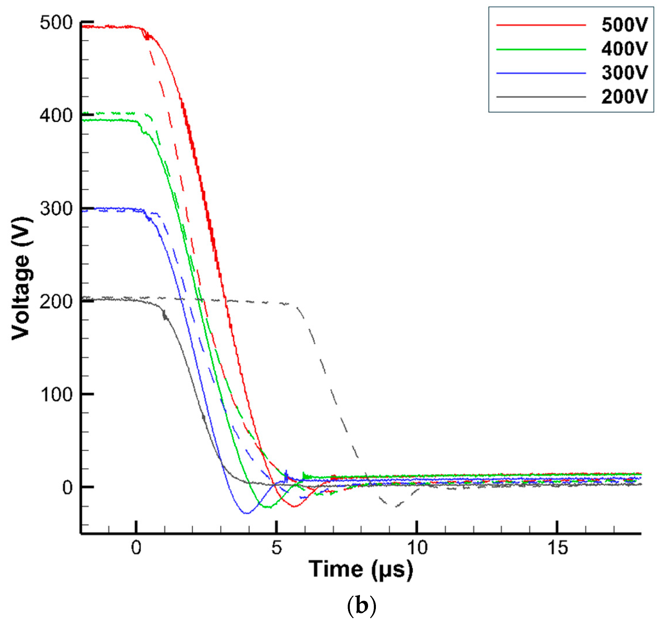
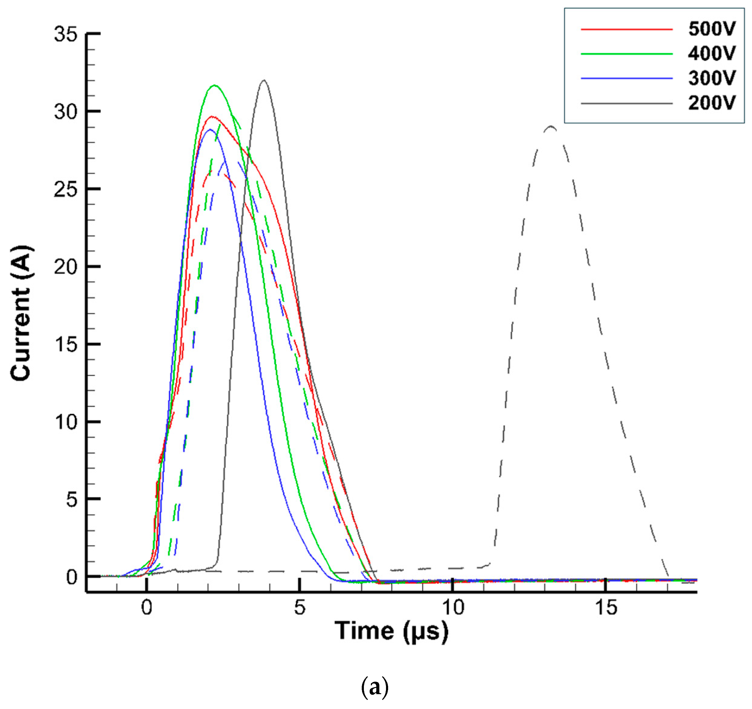
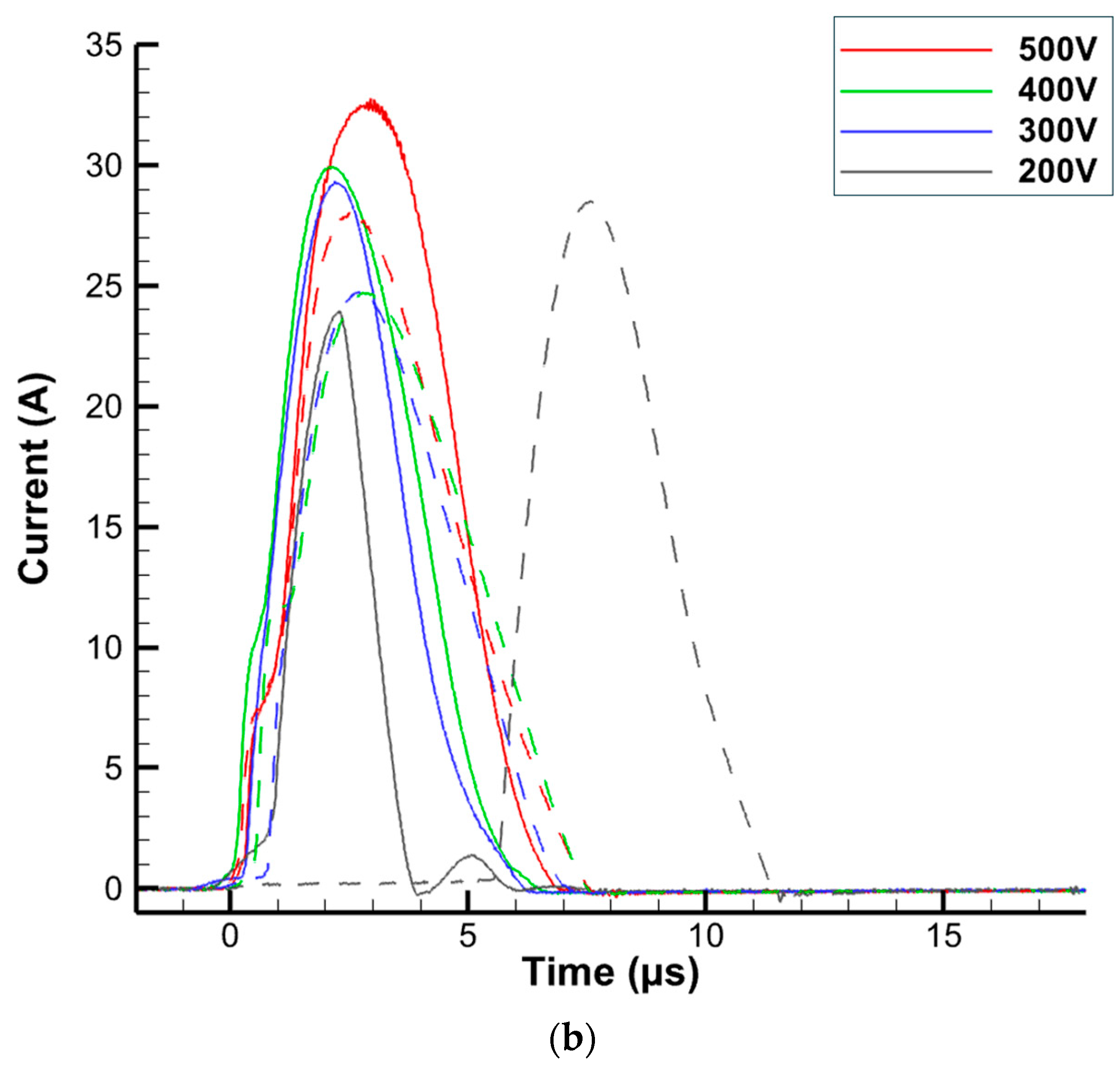
The operation of the VAT pair with the compact array PPU produced smooth, generally monotonic discharge profiles across all capacitances and voltages, with the exception of occasional fluctuations near the end of the pulse, likely due to wire inductance. The data show some random variation in the ignition process on a pulse-by-pulse basis. Both the 0.22 µF and 0.1 µF capacitors exhibited similar discharge times, suggesting that the discharge duration is limited by the ignition and arc formation processes rather than by the capacitance or circuit resistance. The maximum discharge current generally increased with voltage, though not in all cases, with variation likely introduced by the ignition process. There was a visible and significant delay in the discharge onset from the pulse initiation for 200 V capacitors. This suggests that 200 V is approaching the minimum voltage required for the rapid vaporisation of the thin conductive layer.
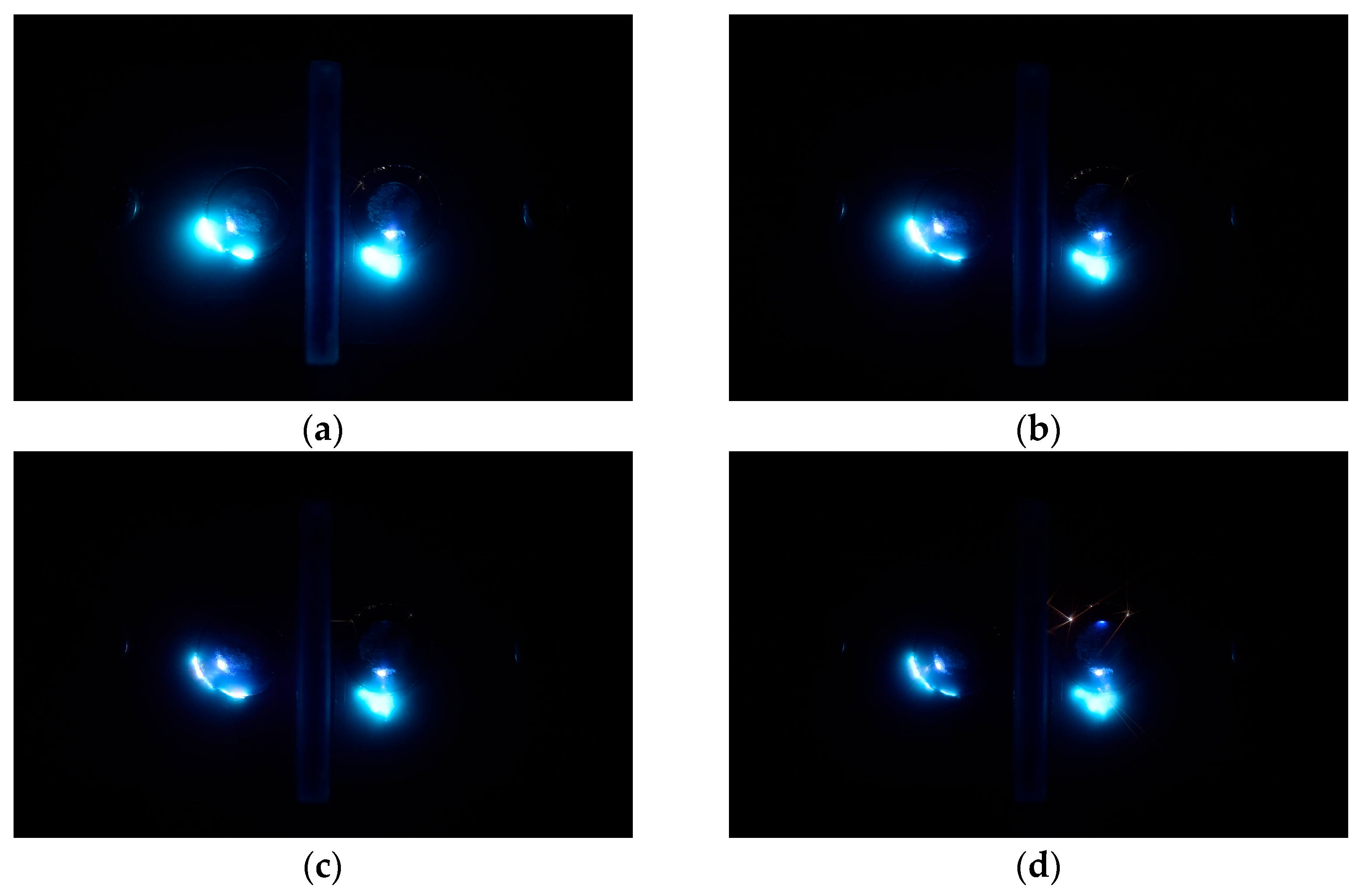
Visible cathode spot formation operating on the high-voltage capacitors demonstrates the successful operation of the thrusters using the compact array PPU architecture. However, at a discharge energy of 4 mJ (corresponding to 0.1 µF capacitance at 200 V), reliability issues were encountered, as demonstrated in
Figure 16d, which shows that the left-hand thruster failed to ignite. This is consistent with the reliability data presented in
Table 2 for the VAT array PPU. As plasma formation by the ignition capacitors is required to initiate the discharge of sustainer capacitors, the reliability results presented in
Table 2 also apply to the compact array PPU configuration. The noticeably brighter triggerless ignition sites observed with decreasing voltage in
Figure 15 and
Figure 16 may also indicate increased energy dissipation in the thin conductive layer at lower pulse energies, which could negatively impact thruster efficiency.
The testing results of both the standard and compact array PPU configurations confirm the successful operation of VATs, demonstrating the viability of both PPU concepts. While some configurations exhibited reliability issues at lower ignition energies, higher ignition energies consistently resulted in stable performance, and the optimisation of the thruster architecture could further enhance reliability. Propulsion system designs using the compact array PPU architecture may benefit from smaller thrusters, as the short-duration pulses produced may cause uneven cathode erosion on larger cathode surfaces due to limited cathode spot propagation. This study also demonstrates the ability to isolate ignition energy from the primary discharge energy source, allowing ignition energy to be studied directly and more compact ignition systems to be designed.
The proposed PPU concepts enable the controlled operation of VAT arrays on highly constrained CubeSat platforms, where traditional PPU designs are either too bulky or suffer from significant control limitations. The precise operation of VAT arrays facilitates many propulsion system possibilities, such as the concept presented in
Figure 3, that can provide increased total impulse, attitude control, and propulsion redundancy to nanosatellites. These designs remove the need for complex propellant feed mechanisms and dedicated attitude control hardware, further optimising mass and volume budgets. Alternatively, they can serve as a redundant control system, improving reliability and providing momentum-dumping capability. The mass and volume benefits of the proposed PPU architecture scale with the size of the thruster array, extending its potential application beyond CubeSats to larger propulsion systems.
The compact array PPU offers additional capability through precisely controllable thruster impulses, enabling high-resolution velocity adjustments. This is particularly beneficial for applications such as precision spacecraft pointing and formation flying, which represent a significant portion of the nanosatellite market. The standard and compact PPU configurations can be integrated into a single system, with the associated thruster array divided into high-impulse and precision-control thruster segments. This is achieved with a shared inductive energy ignition circuit and separate IGBTs to control each array section. Sustainer capacitors supply the high-impulse thrusters, while small, high-voltage capacitors power the precision-control thrusters. In this configuration, a single propulsion system can deliver high-impulse primary propulsion while also enabling precise spacecraft pointing and manoeuvring.


