Abstract
Using generally available geometric data, calculations of wetted and projected areas of major components, that is, wings, fuselages, empennage, and engine nacelles, for 55 airplanes were compiled into a database comprising four groups: commercial, supersonic, all-wing, and military airplanes. Attention is primarily focused on subsonic and supersonic commercial airliners, and the wetted areas of the components of each are discussed and shown to be reasonably estimated by simple functions of airplane geometry, like gross wing planform area, fuselage length and diameter. Comparisons of total wetted areas of 13 commercial airplanes and 5 military airplanes with results reported by 14 independent studies showed good agreement. Total wetted areas for all the airplanes were shown to be well-represented by simple functions of wing planform area S alone. Relationships between the projected and wetted areas of the commercial airplanes were explored to illustrate the implications for airplane design, including accommodation of fuselage stretch, trends in component wetted area fractions, correspondence of wetted areas to planform envelope—that is, the product of wingspan and fuselage length, relation of frontal areas to wetted areas, and application of a planform configuration parameter, B = (bAR)3/16(1 + 3.5/AR9/4)−1/2, to estimation of (L/D)max—and prediction of wetted area as a function of gross weight based on the square–cube relation between area and volume.
1. Introduction
Airplane design is driven by mission specification. Commercial airplanes are typically called upon to carry a specified payload over a particular range at a given altitude and speed. These general requirements imply certain restrictions on the basic airplane elements: gross weight Wg and aerodynamic and engine fuel efficiency ((L/D) and cj, respectively). Choosing representative values for these basic items generally relies on a historical database of previously designed airplanes. The payload for commercial airplanes is primarily the number of passengers and arranging them in a convenient manner provides information on the envelope of the cabin: length, breadth, and depth. Aerodynamic considerations then set the forward and aft components of the fuselage, thereby essentially specifying the overall fuselage length. With overall characteristics in hand, the design proceeds with more detailed performance, stability, and safety requirements, not the least of which is the large body of government regulations that must be met, which impose constraints on the next level of configuration characteristics, such as wing and tail areas, as well as the number and size of the engines needed. At this point, the basic envelope of the airplane is approximately designed. Further specific details, such as wing planform shape, tend to be driven by aerodynamic performance issues like lift and drag.
In preliminary design, drag analyses begin with the zero-lift drag of an airplane, often estimated by the drag component build-up method in which the zero-lift drag of each airplane component, such as the wing, fuselage, etc., is calculated independently and the results are summed. For flows that are not near separation, the drag Di of component i is typically expressed as a multiple, ϕi, often called a form factor, of the friction drag Df,i of that component, so that the zero-lift drag of the airplane may be written as the sum of the drag contributions of each of the n components. However, the appropriate forms, functional dependencies, and magnitudes of the ϕi correction factors are open to contention and many approaches have been considered [1,2,3,4,5]. This method involves detailed knowledge of the geometry of the airplane so that the wetted areas of each component may be accurately calculated. In addition, estimates of the contribution of excrescences such as antennas, fairings, etc., as well interference effects, must be carried out to ensure an accurate depiction of the zero-lift drag of the airplane.
Therefore, evaluating variations of a given design or performing comparisons with competing designs requires substantial effort and time in calculating wetted areas. A simple estimation method for wetted areas that provides reasonable accuracy with a minimum amount of dimensional information would be a useful complement. The present study uses a simple method for calculating the wetted areas, based on previous work [6]. The airplane configurations considered are relatively conventional with essentially planar wings and are of a scale typical of manned vehicles. The principal areas of interest in airplane aerodynamics are the reference area, typically the projected wing planform area, the wetted areas of the airplane, and the projected frontal area of the airplane. Important geometric quantities include span b, length l, and the mean aerodynamic chord of the wing cmac.
Of particular interest here is the relationship between various projected and wetted area characteristics and similarity parameters for commercial aircraft covering a broad range of subsonic and supersonic commercial airplanes. To this end, we start by assembling a database of calculated component wetted areas for 55 airplanes which may be broadly divided into five groups. The subsonic commercial group includes a business jet, five regional turboprops, five regional jets, and twenty-six commercial turbofan transports, including a proposed truss-braced wing [7] (NASA TBW) turbofan transport. The supersonic group includes three commercial airliners and two supersonic bombers, added for comparison purposes. The all-wing group is composed of three airplanes, while the military group has nine military airplanes, including two swing-wing bombers, a subsonic bomber, three subsonic jet transports, and three propeller transports. The gross weights of the airplanes in this database range over two orders of magnitude, from 12,500 lbs to 1,234,600 lbs. Although the main interest resides in commercial airplanes, the others have been included to broaden the parameter space, permit the pursuit of some diverse aspects of projected and wetted area trends, and provide additional cases to evaluate the wetted area calculations presented. Geometric data for these airplanes were drawn mainly from airport planning manuals for commercial airliners and three-view drawings and similar data for military aircraft, all of which was available online. The basic geometric data for the airplanes considered and their total wetted areas, as calculated by the methods of this study, are given in Table 1.

Table 1.
Basic data for the airplanes studied.
The next section of the paper is devoted to calculating the wetted areas of the major components of the commercial airplanes: wing, fuselage, tail surfaces, and nacelles. Simple correlations for the wetted areas of these components are derived which depend only on the gross wing planform area S or the nominal projected fuselage area ld. Summation of the component wetted areas yields total wetted areas which, when compared with values for 13 commercial airplanes and 5 military airplanes reported by 14 independent studies in the open literature, show good agreement. Finally, the total wetted areas are shown to be described well by a simple power law of the gross wing planform area alone for each of the five groups of airplanes. Thus, the total wetted area is largely a function of the design wing planform area alone.
Then, the interrelations between the projected and wetted areas for the commercial airplanes are discussed. The influence of fuselage stretching on wetted area predictions are described, particularly the practice of generating a family of similar airplanes with fixed planform area but increasing fuselage length to accommodate additional passengers. The trends of the component wetted areas as fractions of the total wetted area are illustrated, the relation of the planform envelope bl to the total wetted area Sw is examined, and the correlation between frontal area and wetted area is investigated. The relationship between aspect ratios based on either wing planform area or on total wetted area illustrates the differences between different airplane configurations. The magnitude of (L/D)max is shown to be directly proportional to a new planform configuration parameter, B = (bAR)3/16(1 + 3.5/AR9/4)−1/2, which is large for slender wings of great span for a given planform area. Several cases of airplanes of dissimilar configurations but similar values of projected or wetted areas are examined to illustrate the influence of these properties on performance. Finally, the relationship between maximum gross weight and total wetted area according to the square–cube law is examined and evaluated.
2. Wetted Area
The wetted area in the clean configuration for en route flight, apart from terminal operations, may be simply approximated by the sum of the wetted areas of the major components of the airplane:
Attention is focused solely on the major components of the airplane, the wing, fuselage, tail, and nacelles, which are denoted by the subscripts w, s, t, and n, respectively. The term ΔSw in Equation (1) denotes any increment in wetted area due to unusual features of substantial size, like wingtip tanks or fuselage protrusions, which are to be treated individually where they arise. A scaled three-view drawing of an airplane will generally provide sufficient information to accurately calculate the gross and exposed planform areas of most airplane components. The parameters used to characterize the wetted areas are the gross wing planform area S, the fuselage length l, and the effective fuselage diameter d. The gross wing planform area S is defined here as that formed by extending the leading and trailing edges to the fuselage centerline, as shown in Figure 1. This definition of the reference area is commonly used, but other definitions have been used by some airframe manufacturers and researchers, and care must be taken to avoid errors in comparing aircraft aerodynamic data. The effective fuselage diameter is taken as the average of the maximum width w and height h of the fuselage cross-section. This approximation, d = (w + h)/2, is based on the perimeter of an elliptic cross-section and is accurate to 1% or less for 0.75 ≤w/h ≤1. Using consistent methods described in the following sections, the component wetted areas of all the airplanes were calculated and summed, yielding the wetted areas Sw listed in Table 1.
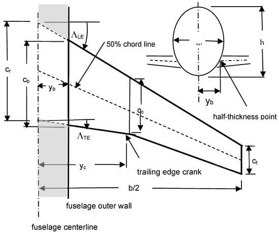
Figure 1.
Typical airplane wing with swept leading and trailing edges and one spanwise crank. The unshaded area represents half the gross planform area S used as the reference area in this study.
2.1. Wing Wetted Area
The planform area of a wing of the type shown in Figure 1 may be expressed as the sum of the areas of the trapezoidal inboard and outboard wing panels, yielding
Here, ct is the tip chord, cc is the chord at the location of the crank in the wing’s leading and/or trailing edge and cr is the root chord; the wingspan is b and the spanwise location of the wing crank is yc. This equation and others developed here apply to wings with leading and trailing edges comprising straight segments which may be cranked at a single spanwise location. The gross planform reference area calculated in this manner was applied to all airplanes to maintain consistency; they were within ±1% of the values cited in the open technical literature, except for those few which were based on different definitions of reference area.
The wing wetted area may be found by first determining the exposed planform area of the wing and then accounting for the perimeter of the chordwise sections of the wing. The exposed surface area of the wing is given by
Equation (3) for the exposed wing area properly excludes the portion of the wing covered by the fuselage, as illustrated in Figure 1. This formulation does not consider any blanketing of the wing surface caused by pylons, flap fairings, etc. If such effects are large, e.g., under-wing engine ducts on supersonic airplanes or wing-mounted nacelles of propeller-driven airplanes, they are deducted from Equation (3) on a case-by-case basis.
The airfoils in airplane wings typically have a maximum thickness ratio (t/c)max = O(10−1). Calculations of the ratio of perimeter length to chord length, p/c, for three representative NACA airfoils (63-209, 631-212, 632-215) and two representative NASA supercritical airfoils (SC2-0412 and SC2-0614) show that p/c can be fit to within ±0.4% by the simple nonlinear approximation
Using the approximate expression for the perimeter given by Equation (4), the differential element of the wetted area for a typical wing is p(y)dy = 2[1 + (t/c)max2]cdy. Integrating this over the exposed span yields an approximate expression for the wetted area as follows:
Note that the expression on the far right-hand side of Equation (5) assumes a constant value for (t/c)max throughout the span; wing thickness ratios and data on root and tip thickness ratios are presented, for example, in Ref. [5]. For preliminary design purposes, a constant average value of (t/c)max is generally adequate for use in accurately estimating wing wetted area. If the thickness ratio of the wing is unknown, it is reasonable to use values of 0.14 for turboprops, 0.12 for turbofans, 0.19 for all-wing airplanes and 0.035 for supersonic airplanes.
The wing wetted areas calculated for the commercial group in Table 1 are shown in Figure 2. Most airplanes are seen to follow the simple relation
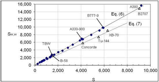
Figure 2.
Wing wetted areas are shown as a function of the gross planform area S. Areas are measured in ft2.
In total, 35 of the 37 commercial airplanes fall within ±4.7% of Equation (6); the 2 remaining airplanes in the commercial group, the Do328 and the NASA Truss-Braced Wing (TBW), are underestimated by 7.8% and 11.8%, respectively. In general, the wing wetted area of the subsonic military airplanes tend to be about 9% larger than commercial airplanes of the same wing planform area.
Three of the airplanes in the supersonic group (Concorde, Tu-144, XB-70) have fully ducted engines and their wing wetted areas are found to fall within ±3.8% of a third trend given by
The ducted engines of these three airplanes blanket a relatively large area of the lower surface of the wing, thereby reducing the wing wetted area. The remaining airplanes in the supersonic group, the B2707 and the B-58, have podded engines like the commercial group, which explains why their wing wetted areas also follow Equation (6) and lie within the same error band. Note that the X-B70 and B-58 supersonic bombers were added to the commercial supersonic group to expand the wing planform area parameter space.
2.2. Fuselage Wetted Area
The fuselage of length l is assumed to be composed of three sections: a nose cone of length lnc, a cabin, and a tail cone of length ltc. The nose cone is assumed to be a parabola of revolution followed by the cabin, which is a cylinder of effective diameter d, and ending with a right circular tail cone. The effective diameter of the cabin is assumed to be given by , where w and h denote the maximum width and height of the cabin, respectively. For elliptical cross-sections with 0.8 < w/h < 1.25, the effective diameter yields a perimeter accurate to ±0.7%. Some judgment must be applied in defining the fuselage segments, particularly if one is treating military aircraft. The bases of the nose cone and tail cone are typically assumed to be located at the forward and aft stations where reductions in cabin cross-sectional area are observed. This formulation does not consider any blanketing of the fuselage surface caused by attachment of wings, tail planes, etc. An allowance for appendages of substantial size, like large landing gear fairings used on some transport airplanes, is provided by a term denoted by ΔSw,f. For such a model of the fuselage, the wetted area may be approximated by [5]
According to Equation (8), the fuselage wetted areas of the airplanes should be well-correlated by the product ld. However, there is a tendency for the wetted area to increase slightly more than linearly with ld because lnc/l and ltc/l decrease as l increases, as would be the case when a plug is added to lengthen a fuselage.
As expected, the fuselage wetted areas of the airplanes are well-correlated by the product ld as illustrated in Figure 3. The fuselage wetted areas for almost all but two of the airplanes considered are correlated by
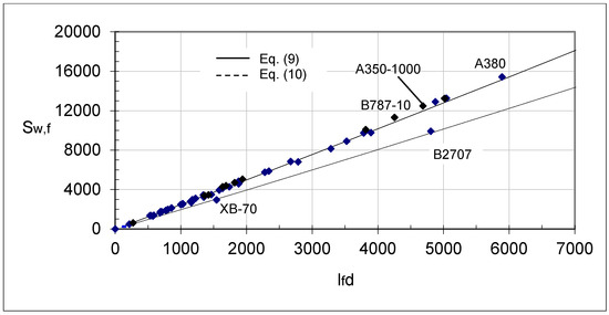
Figure 3.
Fuselage wetted areas are shown as a function of the product of fuselage length and effective diameter. Lengths are measured in feet and areas in ft2.
However, for fuselages with particularly slender tail cones, ltc/d > 5.5, the coefficient of Equation (9) is reduced so that
Only two airplanes, the XB-70 and the B2707, fall into this latter category and are identified in Figure 3. The B-58, which has ltc/d < 5.5 and ld = 529, falls near the curve given by Equation (9), but, for clarity, is not identified in Figure 3. The data for all the airplanes considered are within ±6% of the correlations given by Equations (9) and (10).
2.3. Tail Surface Wetted Area
The tail wetted areas may be calculated using an approach like that for the wing wetted area. A schematic diagram of the horizontal and vertical tail surfaces and their dimensions is presented in Figure 4.
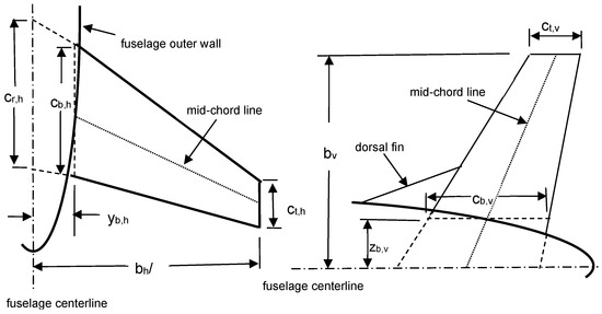
Figure 4.
Schematic diagram of horizontal (left) and vertical (right) tail surfaces showing dimensions used in determining wetted areas.
The total wetted area of the tail surfaces is given by
The quantity Sw,d is the wetted area of the dorsal fin, if any. Results for the horizontal tail wetted areas of commercial airplanes are presented in Figure 5, where it is seen that most of the data follow a trend given by
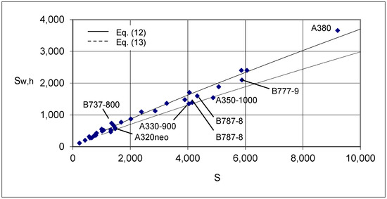
Figure 5.
Horizontal tail wetted areas are shown as a function of the gross planform area S. Areas are measured in ft2.
However, it is also apparent that newer airplane models generally show a smaller horizontal tail wetted area for a given wing planform area, with
Equation (13) represents a 15% reduction in the general trend of Equation (12). Errors are more substantial than for wing or fuselage wetted area, with two-thirds within ±10% and the remainder within ±20%. The supersonic airplanes are not represented in Figure 5 because those considered have no horizontal tails.
Vertical tail wetted areas for the commercial airplanes are shown in Figure 6 and clearly illustrate a curious inflection in the trend of the data. For S < 2400 ft2, the data follow the following trend:
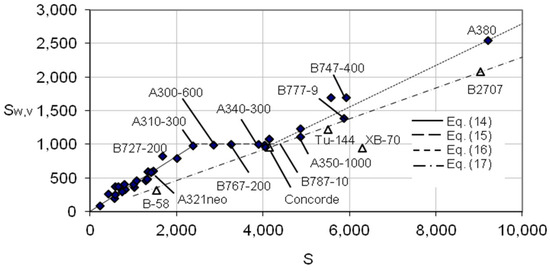
Figure 6.
Vertical tail wetted areas are shown as a function of the gross planform area S for both subsonic and supersonic commercial airplanes. Areas are measured in ft2.
The scatter about Equation (14) is the least for the 13 airplanes with 1000 ft2 < S < 2400 ft2, being ±6% for 8 of the 13 and ±17% for the others. For the remaining 11 smaller (S < 1000 ft2) airplanes, the scatter was substantially greater at ±30%. However, for the seven airplanes in the range 2400 ft2 < S < 4300 ft2, the wetted area is approximately constant and given by
The errors associated with Equation (15) are within ±7%. Finally, for S > 4300 ft2, the data follow the trend given by
The errors in this planform area range are within ±10%, except for the B747-200 (−16%), which shares the same vertical tail with the B747-400, but has a smaller wing planform area.
The vertical tail wetted areas for the supersonic airplanes are shown in Figure 6 to have a clearly defined trend which may be approximated by
The data fall within ±7% of Equation (17) for all the supersonic airplanes except the XB-70, which is over-predicted by 47%. This apparent deficiency in vertical fin area for the XB-70 was accommodated by folding down the 521 ft2 outboard wing sections 65° during operation at high supersonic speeds to improve directional stability.
Although the focus here is on the commercial airplanes, it is interesting to note that like the commercial airplanes described by Equation (15), the military airplanes show a similar plateau in Sw,v of about 620 ft2 in the range 1600 ft2 < S < 2500 ft2.
2.4. Nacelle Surface Wetted Area
Most commercial jets have pod-mounted engines, such as that illustrated in Figure 7. In such cases, the nacelle wetted area is taken as the area of the outer shell wetted by the airstream and discounts any surface wetted by air that has passed through the fan or the engine core. Because the cross-sections of nacelles are often close to circular, the total wetted area for nn nacelles of effective diameter dn and length ln is estimated as follows:
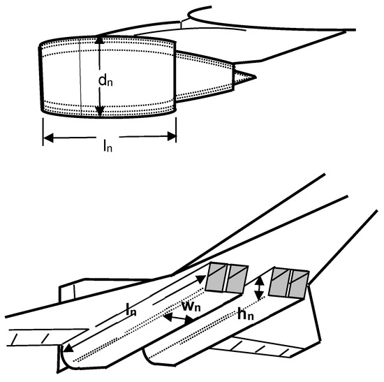
Figure 7.
Schematic diagram of typical nacelle configurations showing dimensions used in determining wetted areas.
The effective diameter of the nacelle dn is taken as the average of its maximum cross-sectional width and height, as was achieved previously for estimating the effective fuselage diameter. The factor 2/3 in Equation (18) provides reasonable accounting for the wetted area of the pylons carrying the nacelles. Commercial turboprops have a long, essentially constant cross-section, with wing-mounted rather than nacelle-mounted engines, and show relatively high values of Sw,n compared to commercial jets of similar size. The wetted areas of such nacelles are also calculated using Equation (18) but without the 2/3 factor.
Instead of pod-mounted engines, supersonic airplanes may have engines fed by extensive ducts blended into the lower surface of the airframe, as illustrated in Figure 7. The wetted areas of those nacelles are estimated according to the following equation:
Here, nn is the number of ducts, hn is the maximum duct sidewall height, ln is the duct sidewall length, and wn is the maximum duct width. All or part of the top surface of the duct is blanketed by the wing and therefore is not wetted by the flow.
The wetted areas thus calculated for commercial jets and turboprops with S < 1600 ft2 are shown as a function of wing planform area S in Figure 8, where three trends in the data are apparent. The upper trend describes airplanes with turboprop or older turbofan engines with low bypass ratios, β < 4, for which the nacelle wetted area is given by
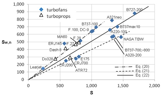
Figure 8.
Total nacelle wetted area as a function of S for commercial jets with S < 1600 ft2. All areas measured in ft2.
The airplanes following this trend are characterized by relatively long nacelles compared to their diameter, resulting in relatively large values of wetted area.
The lower trend is characteristic of airplanes powered by engines with moderate bypass ratios, 4 ≤ β ≤ 8, like the B737-800 and the A320. These modern engines with moderate bypass ratios have relatively large nacelle diameters compared to their length, leading to reduced nacelle wetted area, and they follow the trend given by
Note that the ATR72-500 has unusually short nacelles for a turboprop airplane and therefore is more closely described by Equation (21) than (22).
The intermediate trend is followed by airplanes powered by the latest high-bypass-ratio engines with β > 8, such as those on the B737max10 and the A321neo. The nacelle wetted area for these engines falls between the other two types, largely due to increased fan diameter but little change in nacelle length. For these engines, the appropriate estimation equation for nacelle wetted area is
Note that the nacelle wetted area for the A321neo is considerably higher than the others in its class, being powered by the Leap 1A engine with a bypass ratio of 11 and, consequently, a considerably larger fan diameter than, say, the Leap 1B, with a bypass ratio of 8, which powers the B737max10.
The deviations from Equations (20)–(22) are within ±8% except for the ERJ145, which has an unusually large nacelle wetted area for its wing area, being under-predicted by 23%; the ATR72-500, for which the opposite is true, and is over-predicted by 11%; and the A321neo, under-predicted by 14% for the reasons already discussed.
For subsonic commercial jets with S > 1600 ft2, the data for the total nacelle wetted area form distinct groups depending on the wing area and number of nacelles of a given airplane, as shown in Figure 9. This behavior is largely because the performance and size of available commercial engines vary stepwise rather than continuous fashion. In the range 1600 ft2 < S < 3500 ft2, the wetted nacelle area data fall within ±6% of Sw,n = 932 ft2, while in the range 3500 ft2 < S < 7000 ft2 they fall within ±11% of 1864 ft2. This estimate calls for the wetted area of an average nacelle of about 466 ft2, suggesting that for the four-engine A340, Sw,n should be around 1860 ft2, while it is calculated to be 2022, an error of about −8%. However, for the three-engine MD-11, using this estimate for the nacelle wetted area would yield 1398 ft2, 33% lower than the calculated value of 2090 ft2. This 692 ft2 discrepancy arises from the additional wetted area required for the large tail-mounted nacelle housing the third engine. Larger commercial airplanes in the range 3500 ft2 < S< 6500 ft2 have fans with diameters of 8.2 ft to 9.8 ft, while the GE9X engine of the B777-9 has a fan diameter of 11.2 ft, for which a value of Sw,n = 2300 ft2, a 25% increase, is suggested to be used. Beyond S = 7000 ft2, there is only one airplane, the four-engine A380, which obviously should have twice the nacelle wetted area of the airplanes in the previous wing area range, that is, Sw,n = 3750 ft2.
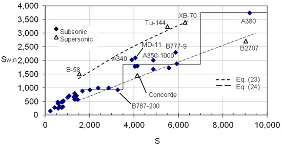
Figure 9.
Total nacelle wetted area as a function of S for airplanes in the commercial and supersonic groups with S > 1600 ft2. All areas measured in ft2.
The nacelle wetted areas for the airplanes in the supersonic group are also shown in Figure 9. The two trends observed are distinguished by the magnitude of the ratio of nacelle wetted area to planform area. Relatively large nacelle wetted areas, Sw,n/S ≥ 0.5, are typical of ducted inlets, as in the XB-70 and the Tu-144. However, turbojet engines with long nacelles, like the B-58, can also have large nacelle wetted areas. A reasonable correlation equation for these large nacelle wetted area cases is given by
For the three airplanes in this category, the deviation of the calculated nacelle wetted areas from the approximation of Equation (23) is ±4%. As a guide, it is suggested that airplanes falling into this category are those having either extensively ducted engines or podded nacelles that are relatively long compared to the fuselage length, ln/lf ≥ 0.2.
For relatively small nacelle wetted areas (Sw,n/S ≤ 0.5), typical of podded engines, Figure 9 shows that an appropriate correlation is
Only two aircraft meet this condition of relatively small nacelle wetted area, and within this small sample the deviation of the data from Equation (24) is ±6%. Airplanes that fall into this category tend to have ducted or podded nacelles that are relatively short compared to the fuselage length, ln/lf < 0.2. Note that the apparent agreement of the nacelle wetted area data for the A350-1000 and the B777-9 with the curve of Equation (24) is purely coincidental.
For the collection of airplanes studied, the nacelle wetted area is, on average, 7% of the total wetted area for subsonic airplanes and 14% for supersonic airplanes. Therefore, the imprecision in estimating Sw,n from the approximate relations given above will have a minor effect on the total wetted area for the subsonic commercial group, while for supersonic airplanes the approximations will have a more noticeable effect, and greater care must be taken. Attention must also be paid to the introduction of ultra-high-bypass-ratio engines whose large fans result in high nacelle wetted areas. For this reason, there is interest in developing unducted fans of large diameter to eliminate the nacelle drag.
2.5. Total Wetted Area
The total wetted area of the airplane may be formed by the sum of the contributions of the component wetted areas:
In Equation (25), the quantity ΔSw denotes any increment in wetted area due to unusual specific features like tip tanks, engine pylons, fuselage protrusions, and the like, which are treated individually. Only ten such increments were used in the current study and those increments contributed less than 4% to the total wetted area in seven cases and equal to or less than 10% in three cases: the B-58 nacelle pylons (5%), the Vulcan nose and tail cones (6%) and the Learjet 23 wingtip tanks (10%). Using methods described in the previous sections and scaled drawings of all the commercial airplanes, the component wetted areas were calculated and are listed in Table 2. Summation of the component wetted areas according to Equation (25) yields the wetted area Sw listed in Table 2 and illustrated in Figure 10.

Table 2.
Component and total wetted areas (ft2).
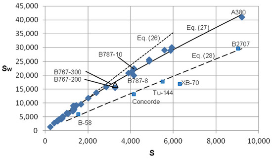
Figure 10.
Total wetted areas of subsonic and supersonic commercial airplanes as a function of S. Curves correspond to correlation equations. All areas are measured in ft2.
For quick evaluations, a simple result, dependent solely on the gross wing planform area S, is obtained by observing that the data in Figure 10 shows the total wetted areas to be well-correlated by the following expressions:
Although the discussions in the previous sections were concerned with commercial airplanes, the same methods have been applied to all the airplanes listed in Table 1, and the resulting component wetted areas are also tabulated for reference in Table 2.
In Figure 10, wetted areas calculated using Equation (25) and denoted by data symbols are compared to correlation curves of Equations (26)–(28). The data for the 22 subsonic commercial airplanes with S < 2000 ft2 fall within ±8% of Equation (26), with two exceptions: the Do328 (−10%) and the A321neo (−13%). The 15 remaining airplanes fall within ±4% of Equation (27), except for the B-767-200, which falls below the correlation by 12.9%. Interestingly, this is the only airplane represented in the range 3000 ft2 < S < 4000 ft2, a range of wing area that showed changes in behavior of both the vertical tail and nacelle wetted area. Note that the B767-300 is a stretched version of the B767-200, having a 21 ft fuselage plug resulting in an additional 1130 ft2 of wetted area, while sharing the same planform area as the B767-200. The wetted area predicted by Equation (25) for the B767-300, 16,700 ft2, is shown in Figure 10 as an open triangle symbol lying approximately on the correlation value of Equation (27). A similar situation arises for the A320 and A321 family and the B787-8 and 787-10, as seen in Figure 10. Because the correlations offered depend solely on gross wing planform area, some caution must be applied when considering families of airplanes where a stretched version may share the same wing planform with the original version. It has been pointed out [8] that a wing may be over-designed for the initial version of an aircraft family so that it need not be altered when future family members grow in weight by fuselage stretching, illustrating one of the problems that may arise from the use of arbitrary reference areas like the planform area S used here.
Although the interest here is in commercial airplanes, it is worth noting that the wetted areas of the subsonic military planes follow the same functional form as Equation (27), but with a coefficient of 15.28. This indicates that the military designs have larger wing areas than those of commercial airplanes with the same wetted area. The deviations from the detailed values given by Equation (25) are within those quoted for the commercial airplanes, apart from the C-5A, which is under-predicted by 26%. Indeed, the C-5A wetted area falls in line with the commercial airplane results. The all-wing military airplanes, which do not cover a wide range of S, also appear to follow the functional form of Equation (27), but with a coefficient of 8.2.
Wetted area data for four of the five supersonic airplanes are within ±5% of those calculated by Equation (28), while the other one, the XB-70, is over-predicted by 21.8%. The wetted area of the XB-70 is over-estimated by the correlation of Equation (28), primarily because of its relatively small fuselage wetted area. Indeed, the XB-70’s 3000 ft2 deficit in Sw is about equal to the difference between its fuselage wetted area and that of the Tu-144, an airplane remarkably similar in size and configuration.
The total wetted area results for the remaining four airplanes are underestimated by 5% to 10% because they have unusual design features not accounted for, as they are in Equation (25): the Learjet 23 (−7.2%, tip tanks), Dash 8 (−5.9%, large dorsal fin), TBW (−8.1%, strut), B747-200 (−5%), B747-400 (−6%), and B-58 (−9.7%, large nacelle pylons). This simple estimation procedure for the wetted area is recommended because, with due care, it is quite faithful to the more rigorous development, yet it is easily and rapidly carried out with knowledge only of the basic dimensions S, lf, and d.
Rather than carrying out the detailed calculations of Equation (25) or using simple correlation curves, one may instead substitute the correlations for the wetted areas of the components that are suggested in the previous sections and summarized in Table 3. Summing up those contributions leads to the total wetted area, as follows:

Table 3.
Summary of approximate equations for component and total wetted areas. (All lengths in ft and areas in ft2.)
Note that, again, in this approximation, no increments for unusual design features are applied. This approximate formulation for total wetted area agrees with the detailed calculations of Equation (25) to within +3% to −5% for 33 of the 37 airplanes of the commercial group, except for the Learjet 23 (−7%), NASA TBW (−8%), and B747-400 (−7%). For six of the seven supersonic airplanes, the error ranged from −4% to +1%, the only exception being the B-58 (−10%). All the airplanes that fell out of the smaller error bands were those which had unusual design features that, if accounted for, would have markedly reduced the errors. This simple build-up of the wetted areas is recommended because it is quite faithful to the more rigorous development and provides the wetted areas of the components, yet it is easily and rapidly carried out with knowledge only of the basic dimensions S, l, and d. For convenience, a summary of the individual functions in Equation (29) for commercial and supersonic airplanes is provided by Table 3.
Although not treated in detail in this study, wetted area approximation equations for the all-wing and military airplanes are included in Table 3 for reference.
2.6. Accuracy of the Wetted Area Correlations
Total wetted areas of the 55 airplanes of Table 1 were calculated in a consistent fashion using scaled drawings taken primarily from online airport planning manuals as well as other sources such as Jane’s All the World’s Aircraft, Aviation Week & Space Technology, NASA reports, etc. To provide some sense of the accuracy that may be expected from the methods presented, results of the present investigation for 13 commercial airplanes and 5 military airplanes are compared to those reported by 14 independent studies in the open literature.
In Table 4, four values for the total wetted area of each airplane are presented: Sw as reported by the cited reference, Sw calculated according to the summation of detailed evaluation of components as given by Equation (25), Sw calculated by using the sum of the simple approximation equations for the component wetted areas as given by Equation (29), and Sw according to the simple correlations of Equations (26)–(28) are shown, along with the percent differences from the reported values. All wetted areas were rounded to three significant figures. Table 4 illustrates that the simplified methods presented here yield reasonable results for the total wetted areas. The results for wetted area using Equation (25) are within +4% of the cited values. The sum of the correlations for each component, Equation (29), which neglects any ∆Sw to account for unusual configuration features, is not generally much less accurate than the more detailed calculation of Equation (25) and is often useful for a quick evaluation of the contributions of the components or simply to estimate the wetted area of a given component. As might be expected, the correlations of Equations (26)–(28) are still less accurate (again, no increment ∆Sw is considered with this method), but are simple and require only the planform area S to estimate Sw. Several cases listed in Table 3 show substantial differences in error between the different proposed methods, thereby pointing out the need for care in applying them. Therefore, when using this estimation method, attention must be paid to any unusual design characteristics that would appreciably affect the wetted area.

Table 4.
Comparison of reported wetted areas (in ft2) with those calculated by the present methods.
3. Influence of Projected and Wetted Areas on Design
3.1. Accounting for Fuselage Stretch
As noted previously, both the subsonic and supersonic wetted area data of Figure 10 show minor deviations from the correlation curves because the planform area is the only variable, thereby missing the contribution of fuselage stretches to wetted area. This may be corrected by considering a new variable, S + ld, which incorporates both the wing and the fuselage planform areas yet still depends only on parameters basic to a preliminary design. By plotting the calculated values of Sw as a function of the nominal planform area S + ld, instead of S alone, as in Figure 10, we obtain the results shown in Figure 11. The wetted areas for both the subsonic and supersonic airplanes are seen to vary linearly with the nominal planform function S + ld, yielding the following correlations:
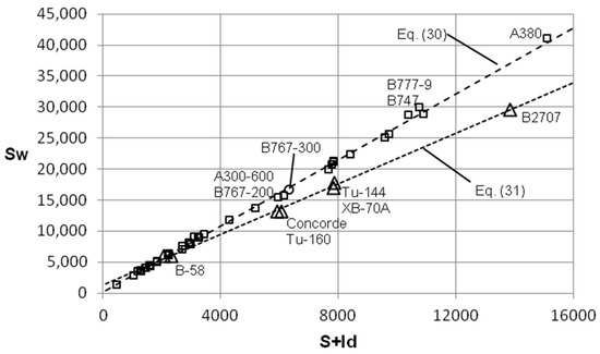
Figure 11.
Total wetted area as a function of the nominal planform area S + ld. All areas are in ft2.
Not only is the behavior linear throughout the full range of S + ld, but now all commercial airplanes are found to follow Equations (30) and (31) with better accuracy than Equations (26)–(28), ±5%, except for the B-47, the NASA TBW, the B-58, and the C-141A, which are underestimated by 10.2%, 6.7%, 6.5%, and 5.3%, respectively. The TBW and the C-141A had added wetted area components because of their unconventional configurations; if these were added to the correlation curve results, the sum would fall within the ±5% error band. The B-47 also had an added Sw increment, but it would not account for the rather large deviation observed. It should be mentioned that both the B-47 and B-58 have relatively short and narrow fuselages, likely because of design choices connected with military mission requirements. Considering the broad range of agreement displayed, using S + ld as the metric mitigates the problem associated with estimating wetted areas of airplanes with a given wing planform and different fuselage lengths, as is found in families of commercial airplanes.
3.2. Trends in Component Wetted Areas
Ratios of component to total wetted area for the commercial airplanes are shown as a function of wetted area in Figure 12. The wing wetted area fraction appears to be the only component that shows a clear increase in the fraction of wetted area, to 38% from 25%, as the total wetted area increases. The fuselage wetted area fraction, on the other hand, remains roughly constant for the most part, between 44% and 52%, while displaying the widest scatter, 36% to 56%, particularly for smaller airplanes, Sw < 10,000 ft2. The combined horizontal and vertical tail wetted area fraction varies between 10% and 20%, with an average of about 15% for Sw < 20,000 ft2, dipping down to around 11% in the range 20,000 ft2 < Sw < 25,000 ft2, and rising back up to about 13% thereafter. The nacelle wetted area fraction shows scatter from 6% to 12% for Sw < 10,000 ft2, dropping to around 6% to 8% for larger values. Overall averaging for the subsonic commercial airplanes shows that the fuselage accounts for about 47% of the wetted area of the airplane, the wing about 30%, the tail 14%, and the nacelles 9%.
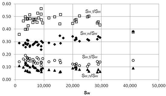
Figure 12.
Component wetted area ratios as fractions of total wetted area for the subsonic commercial airplanes. Areas measured in ft2.
The three commercial supersonic airplanes have a different breakdown of average wetted area ratios, with the wing and fuselage values essentially interchanged from those of the subsonic airplanes, with around 45% accounted for by the wing and 35% for the fuselage, while nacelles account for 13%, about 50% greater than the value for subsonic airplanes, and the tail for 7% (these airplanes have only vertical tails). The increased wing wetted area is largely due to the need to deal with the reduced lifting capabilities of highly swept wings, while the high nacelle wetted areas attest to the increased importance of efficient inlets in supersonic flight. For the two military supersonic airplanes included in the group, each of which has a different mission, the average wing wetted area fraction is 47%, about the same as that of their commercial counterparts, while the fuselage and nacelle fractions are about the same at 23% each, and the tail remains at around 6%.
As a point of interest, subsonic military airplanes display figures lying between those of the commercial and supersonic airplanes with 37% for the wing, 38% for the fuselage, 15% for the tail, and 9% for the nacelles. Only the C-5A falls more toward the averages of the subsonic commercial airplanes, with 35% for the wing and 48% for the fuselage, illustrating its design mission of cargo transport.
3.3. Planform Envelope and Wetted Area
The design constraints on practical airplanes result in distinct relationships between their geometric measurements. For example, the projected planform area bl is essentially linearly proportional to the total wetted area Sw for both subsonic and supersonic airplanes, with the latter displaying a smaller coefficient of proportionality. This is illustrated in Figure 13 where the scatter in data generally diminishes as the wetted area grows, as clearly shown by the result for the Learjet 23, included here to ensure representation at the smallest practical scale. Note that the NASA TBW airplane shows a larger value of bl for its total wetted area than would be suggested by the trend of the data. This is primarily due to the extremely large span of the NASA TBW wing compared to the other airplanes, an instance of the airplane moving out of the conventional design space.
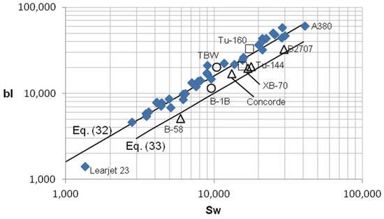
Figure 13.
Variation in the projected area bl with total wetted area. Triangle symbols denote supersonic airplanes. Tu-160 and B-1B, in the swept and unswept modes, are shown as open squares and circles, respectively; all areas in ft2.
As previously pointed out, because only three commercial supersonic airplanes were available, the parameter space was enlarged by adding data for the B-58 and the XB-70, confirming the general trend of the commercial supersonic airplanes. However, in this case, the Concorde lies between the subsonic and supersonic trends, likely due a tail cone even longer than that of the larger Tu-144. The XB-70 does, in this instance, lie close to the Tu-144, an airplane remarkably similar in size and configuration. Another unusual configuration to consider is the variable-geometry planform of the swing-wing Tu-160 and B1-B, shown in the sept and unswept modes in Figure 13 as open square and circle data symbols, respectively. The advantage of variable geometry is the ability to increase both the span and the aspect ratio simultaneously, increasing the achievable (L/D)max substantially, in spite of the increase in wetted area, as will be discussed in detail in a later section.
The all-wing airplanes are clustered on the supersonic trend line lying very close together, just below the B-1B data symbol, and, for clarity, are not represented in the image. It seems surprising that the all-wing airplanes, designed many years apart, occupy so small a design space.
3.4. Frontal Area Relation to Wetted Area
An approximate evaluation of the projected frontal area of the airplanes, excluding flow-through intake area, is given by
The first term on the right-hand side accounts for the lower fuselage bulge for the landing gear usually found on commercial airplanes, with the upper half of the fuselage modeled as a semi-circle and the lower half a rectangle. The second and third terms account for wing and empennage frontal area, the thickness ratios of the wing and tail being taken as constants equal to 12% and 10%, respectively, except for supersonic and all-wing airplanes, where the actual values are known. Using this estimate, Figure 14 shows that the frontal areas of the airplanes considered are essentially linearly proportional to their total wetted areas, with somewhat less scatter than the bl variation in Figure 13. The frontal areas of the all the subsonic airplanes, including the military group, follow one trend, with the supersonic ones along a similar, but lower, trend, while those of the all-wing airplanes are again clustered together, and obviously larger than those of the other airplanes with similar wetted areas. The data is approximately descibed by the following equations:
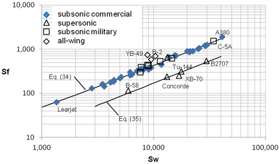
Figure 14.
Variation in frontal area with total wetted area. All areas are in ft2.
The deviations from Equation (34) are within ±8.3% for 32 of the 37 commercial airplanes, with the remainder being within ±15%. The data for the supersonic commercial jets are within a few percent of Equation (35), while the two other supersonic airplanes have wider scatter, as is noticeable in Figure 14. The three all-wing airplanes were so similar in size that trends over the broader range of variables were not discernible, but it is clear their frontal area is larger, for their wetted area, than their more conventional counterparts.
3.5. Aspect Ratios and Their Influence
The drag coefficient is of fundamental importance in airplane performance and may be expressed by the ideal drag polar expression
The first term on the right-hand side of Equation (36) is the parasite, or zero-lift, drag coefficient, which depends upon the wetted and frontal areas. The zero-lift drag coefficient is often expressed in terms of parasite drag area f, defined as follows:
Using the parasite drag area f as a metric of the zero-lift drag coefficient removes the uncertainty connected with the definition of a reference area S, the idea being that a reported value of cD,0S = D/q, the ratio of the drag to the local dynamic pressure, is independent of the reference area used. In turn, the parasite drag area as given by the far right-hand side of Equation (37) depends on an unambiguous reference area, Sw.
The second term on the right-hand side of Equation (36) represents the so-called induced drag, or drag due to lift. The aspect ratio based on planform area AR = b2/S is the parameter that characterizes this contribution to the drag coefficient, in large part because the drag due to lift is proportional to AR−1. In the ideal case k = (πeAR)−1, where e is the so-called Oswald or span efficiency factor, which accounts for non-elliptical spanwise lift distributions.
The nature of these two important similarity parameters and their relation to each other is illustrated in Figure 15, where the wetted area aspect ratio is shown as a function of the conventional aspect ratio. The commercial airplanes are clustered around ARw = 0.17AR in the range 5 < AR < 12, and the subsonic military airplanes occupy much the same region with slightly higher values of ARw. The military and commercial supersonic airplanes follow AR = 0.3ARw in the range of 1 < AR < 3.5, and, like the case for the subsonic airplanes, the military airplanes tend to have a slightly higher ARw for the same AR than do the commercial airplanes. Finally, the all-wing airplanes are near AR = 0.4ARw in the range of 3 < AR < 8. From Equation (37) and the definitions of the two aspect ratios, we see that
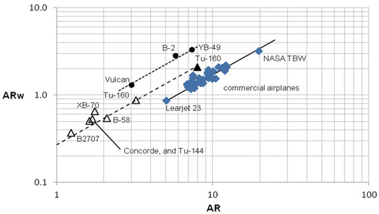
Figure 15.
Wetted aspect ratio as a function of conventional aspect ratio. Straight lines are approximations to the data. Filled triangle symbol denotes Tu-160 in the unswept mode.
Equation (38) illustrates the ratio of skin friction to total parasite drag, which is approximately equal to 17%, 27%, and 40% for the subsonic, supersonic, and all-wing airplanes, respectively. As would be expected, the parasite drag of the subsonic airplanes is dominated by pressure drag due to flow separation, rather than skin friction, while the drag of the all-wing airplanes is almost equally divided between skin friction and pressure drag. The drag division for the supersonic airplanes lies between the other two groups but biased toward higher skin friction contributions arising from the large planform area of delta wings. The XB-70 and the B-58 deviate from the approximating line for supersonic airplanes because of distinctive design differences brought about by their highly specialized missions. The YB-49 and the B-2 have values of ARw close to that of the NASA TBW, but AR values only about one-third that of the TBW, whereby the latter airplane benefits from reduced drag due to lift. The all-wing Vulcan shows similarity to the supersonic Tu-160 in ARw, AR, S, and b, with the major configuration differences being leading edge sweep (45° vs. 65°) and overall length (100 ft vs. 177 ft), suggesting that their aerodynamic characteristics, in subsonic flight, will also be quite similar. The Tu-160 is a variable-geometry swing-wing airplane whose wingspan increases to 177 ft in the unswept mode, changing both aspect ratios, as shown in Figure 15, denoted by a filled triangle data symbol. The resulting point falls on the same trend line as the unswept case, describing the same ratio of friction to pressure drag. However, the increased span and AR ensure much improved aerodynamic performance in the unswept mode of operation. Thus, a change in configuration to increase span and AR may improve aerodynamic performance, but with the penalty of awing-pivot mechanism (Tu-160) or an external wing brace (NASA TBW).
3.6. Influence on (L/D)max Ratios
Although the calculation of component wetted areas is a key element of the drag build-up method, a direct calculation of (L/D)max involving only the aspect ratio and the Reynolds number based on flight conditions and cmac is available and is given by [21]
The mean aerodynamic chord is an unambiguous function of wing planform geometry alone as given by
Using this result for cmac and an exponential approximation for the density variation with altitude z, measured in feet, it can be shown that
Here, M is the flight Mach number, k1 is the planform shape factor in Equation (40), the applicable maximum altitude for this formulation is around 50,000 ft, and the planform parameter is
The first term in parentheses on the right-hand side of Equation (42) is dominant for AR > 5, the second term providing a correction for low aspect ratios. Under typical subcritical cruise flight conditions, the magnitude of the quantity in braces in Equation (41) varies quite little, so that the main functional dependence of (L/D)max resides in planform configuration parameter B. This can be seen in Figure 16, where a variety of results reported [13,21,22] for (L/D)max are shown as a function of the configuration parameter B. Most of the flight data are well correlated by
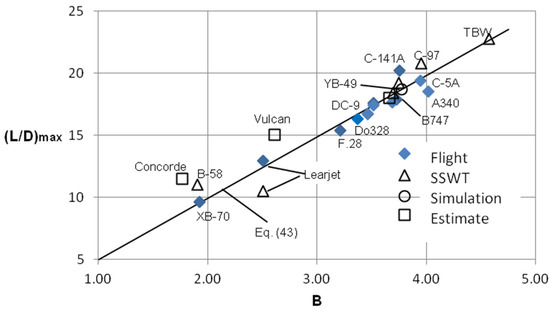
Figure 16.
(L/D)max as a function of the planform configuration parameter B (in ft3/16); data are from Ref. [21]. Faired curve, Equation (43), is shown to indicate the trend.
The available data appears to be in good agreement with the general correlation of Equation (43), particularly the flight data, making it a useful guide to (L/D)max performance. The flight data for the C-141A [15,23] is considerably higher than suggested by its value of B, while the opposite is true for the A340 [12]. The C-141A experiments have substantial documentation [15,23], while the data available for the A340 is far less extensive [12]. The computer simulation [24] of the B747-200 yields results in agreement with Equation (43), while the calculations [13] (called estimates here) for the B-47 and the Vulcan show agreement for the former, but not the latter. Results for the supersonic airplanes are for subsonic flight, with the XB-70 flight test and the B-58 subscale wind tunnel test results being conducted at M = 0.75 and 0.8, respectively. Again, the XB-70 flight test data result agrees well with Equation (43) while the B-58 subscale wind tunnel test result is about 10% higher. The estimate shown for the Concorde is an anecdotal result, regularly appearing in online searches without attribution, said to be for cruise at M = 0.93, which deviates substantially from the correlation of Equation (43), suggesting that it is probably based on subscale wind tunnel testing. Small-scale wind tunnel (SSWT) results are similarly uneven, and this seems to be due to the difficulty of replicating the flight Reynolds number. The Learjet 23 results in Figure 16 show that the flight test result falls on the correlation line, while the SSWT result falls much lower. However, when this airplane was tested in a full-scale wind tunnel (FSWT), the (L/D)max result reproduced the flight test results, so that the data symbols coincide.
As noted in a previous section, the swing-wing Tu-160 and B-1B can increase both b and AR in flight, thereby substantially increasing (L/D)max for efficiency in subsonic cruise. Variable-geometry features of this sort have been confined to military aircraft (F-111, F-14, etc.), the weight penalty being accepted for the sake of achieving mission goals. For commercial aircraft, increased wing span is being explored by passive means, such as extrernal bracing of a slender, high AR wing (NASA TBW), while variable-geometry approaches have been confined to folding outer wing panels (B777-9). Supersonic commercial transports, once again under serious consideration, may be candidates for variable-geometry features.
3.7. Comparisons of Some Dissimilar Airplanes with Some Similar Characteristics
Listed in Table 5 are six airplanes of substantially different configuration and purpose, but with very similar projected and wetted areas, thereby providing useful comparisons.

Table 5.
Comparison of some different airplane configurations.
Same Sw and b: Note that the NASA TBW and the YB-49 are two quite different configurations with very similar values of Sw and b. Though both have high (L/D)max, that of the former is 24% higher. It is likely that the cause of the difference is the higher drag due to lift of the YB-49 flying wing because its aspect ratio is less than half that of the NASA TBW, while its sweepback angle is more than twice that of the TBW. Both airplanes have similar wetted areas and parasite drag areas, while the thick (19%) wing of the YB-49 makes its frontal area more than twice that of the TBW. Recall that the major advantage claimed for the use of an externally braced wing is the ability to carry a very-high-aspect-ratio wing with which high values of L/D may be achieved.
The Vulcan, the C-97 (the military version of the propeller-driven Boeing Stratoliner), and the B737-10, three very different airplane configurations, also have similar wetted areas and wingspans, but different aspect ratios, resulting in significant differences in the magnitude of B and therefore (L/D)max. The highly swept, low-aspect-ratio delta wing of the Vulcan, an airplane which has a resemblance to some proposed blended wing body (BWB) configurations, has a rather low (L/D)max, while the C-97, with an essentially unswept, high-aspect-ratio wing for M = 0.5 flight, shows a 33% advantage in (L/D)max. The sweep and aspect ratio of the B737-10, suitable for high subsonic Mach number flight, has a value of (L/D)max that falls between the two. With esssentially the same cmac, both airplanes should have the same cD,0 when in the same flight conditions.
The B-47 and the B737-10, although designed for very different missions, have close similarities in all metrics in Table 5, except for a 19% larger wetted area for the B737-10. Therefore, under the same flight condtions cD,0 and (L/D)max should be comparable.
Same Sw but different b: The NASA TBW and the B-737-10 are again two different configurations having essentially equivalent values of S and Sw, but the TBW has a wingspan about 50% longer than the B737-10 and an (estimated) (L/D)max about 20% larger.
4. Relationship of Total Wetted Area and Gross Weight
Mueller [22] proposed a general correlation for all flight vehicles over all flight regimes in the form mg = CS3/2, where m is the gross mass of the vehicle, C is a constant with the dimensions of density (that is, a uniform density) and S is the planform area. Mueller suggested that for S measured in m2, C = 1 kg/m3 for hang gliders and some proposed high-altitude long-endurance UAVs, while C > 15 kg/m3 for conventional small and large aircraft, with small aircraft having values of C closer to 15 than large aircraft, while for sailplanes it is perhaps less than 15 kg/m3. Using this approach based on the square–cube law, Durmus [25] proposed considering the characteristic area of an airplane to be its total wetted area, and its volume to be directly proportional to its mass, so that Sw ~ mg2/3 and proposed that Sw ≈ 0.5 mg2/3. Using the values calculated in the present study, the relationship between the maximum gross weight and the total wetted areas is illustrated in Figure 17. A reasonable correlation to the data is given by
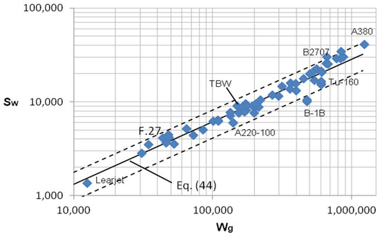
Figure 17.
Variation in total wetted area (ft2) with maximum gross weight (lbs). Dashed lines denote ±30% deviation from Equation (44).
In the metric system, this equation corresponds to Sw = 0.45 mg2/3, quite close to that suggessted by Durmus [25]. An interesting point to note is that, for a given value of total wetted area, there can be a rather wide spread of maximum gross weight. Tacit in the approach is the assumption that the airplane has an average density, uniform throughout, which can only be approximately correct, as the results in Figure 17 show. One design implication may be observed in the case of the variable-geometry B-1B, which has essentially the same wetted area as the NASA TBW, but has about three times the maximum gross weight. This difference is due, in part, to a weight penalty arising from the variable-geometry mechanism needed to increase aspect ratio; the TBW, on the other hand, attains the goal of high aspect ratio by the passive means of external bracing. Another consideration is that the maximum gross weight of a given airplane model often has a variation of 5% to 15%; however, using the operating empty weight (no payload or fuel) instead of the maximum gross weight provides no greater accuracy in predicting the wetted area, again because of the uniform density asssumption. Thus, though the airplane maximum gross weight provides a useful rule of thumb for rough estimates of total wetted area, it lacks the accuracy shown by the use of gross planform area and other specific geometric features, as presented here.
5. Conclusions
Using generally available geometric data, calculations of wetted and projected areas of major components, that is, wings, fuselages, empennage, and engine nacelles, for 55 airplanes were compiled into a database comprising four groups: commercial, supersonic, all-wing, and military airplanes. Attention was focused primarily on subsonic and supersonic commercial airliners, and the calculated wetted areas for each of their components were discussed and shown to be reasonably characterized by simple functions of airplane geometry, like gross wing planform area, fuselage length and diameter. Total wetted areas for all the airplanes were obtained by summation of the component wetted areas and tabulated. Calculated total wetted areas for 13 commercial airplanes and 5 military airplanes were compared to those reported by 14 independent studies in the open literature and found to be in good agreement. Furthermore, the total wetted areas for all the airplanes were shown to be well-represented by power law functions of wing planform area S alone.
The relationships between the projected and wetted areas were explored to illustrate the implications for airplane design. Accommodation of changes in the total wetted area of airplanes of the same family was accomplished by applying the metric S + ld, the sum of gross wing planform area and nominal fuselage planform area, instead of gross wing planform area S alone. Trends of the fractions of component wetted areas with increasing total wetted area demonstrated that for subsonic commercial airplanes, the fuselage accounts for about 47% of the wetted area of the airplane, the wing about 30%, the tail 14%, and the nacelles 9%, while the supersonic commercial airplanes had the wing and fuselage values essentially interchanged from those of the subsonic airplanes, with around 45% accounted for by the wing and 35% for the fuselage, while nacelles account for 13%, about 50% larger than the value for subsonic airplanes, and the tail for 7%. The planform envelope area bl was shown to be directly proportional to the total wetted area, with constants of proportionality being 1.6 and 1.0 for subsonic and supersonic commercial airplanes, respectively. A simple assessment of the wetted area to be expected in very early design stages can therefore be obtained directly from the proposed span and fuselage length.
Calculated frontal areas of the airplanes considered illustrated an essentially linear relation with wetted areas, commercial subsonic airplanes having a larger constant of proportionality than supersonic airplanes, as might be expected because of wave drag penalties in supersonic cruise. All-wing airplanes showed greater frontal area for a given wetted area than the commercial airplanes. The ratio of aspect ratio based on wetted area to that based on wing planform area was shown to be equal to the ratio of equivalent skin friction coefficient to zero-lift drag coefficient, thereby defining the fractions of total zero-lift drag attributable to friction, which is approximately equal to 17%, 27%, and 40% for the subsonic, supersonic, and all-wing airplanes, respectively.
A configuration planform parameter B = (bAR)3/16(1 + 3.5/AR9/4)−1/2 was introduced which correlated (L/D)max results from flight testing. The implications of this parameter for airplane design were discussed and illustrated by examining cases of dissimilar aircraft with similar projected and wetted areas. The relationship between maximum gross weight and total wetted area according to the square–cube law was examined and found to be useful as a rough rule of thumb, although not as precise as the methods presented.
Funding
This research received no external funding.
Data Availability Statement
The data presented in this study are available in article.
Conflicts of Interest
The author declares no conflict of interest.
Nomenclature
| AR | aspect ratio b2/S |
| ARw | wetted aspect ratio, b2/Sw |
| B | planform configuration parameter, Equation (44), ft3/16 |
| b | wing span, ft |
| C | constant |
| c | chord, ft |
| cD | drag coefficient |
| cj | specific fuel consumption |
| D | drag, lbs |
| d | maximum equivalent fuselage diameter, ft |
| dn | maximum nacelle diameter, ft |
| f | parasite drag area (see Equation (37)), ft2 |
| k | constant, see Equation (36) |
| k1 | planform shape factor, see Equation (40) |
| L | lift, lbs |
| l | fuselage length, ft |
| ln | nacelle length, ft |
| M | Mach number |
| mg | airplane gross mass, kg |
| nn | number of nacelles |
| p | perimeter, ft |
| S | gross wing planform area, ft2 |
| Se | exposed wing planform area, Equation (3), ft2 |
| Sf | frontal area, ft2 |
| Sw | wetted area, ft2 |
| t | thickness, ft |
| Wg | airplane gross weight, lbs |
| y | spanwise distance measured from the fuselage centerline, ft |
| z | vertical distance measured from the fuselage centerline, or altitude, ft |
| β | turbofan bypass ratio |
| Λ | sweepback angle (see Figure 1), degrees |
| λ | ratio of local chord length to the wing root chord length, c/cr |
| Subscripts | |
| b | fuselage wall location |
| bottom | nacelle duct bottom wall |
| c | crank in wing planform |
| f | fuselage or friction |
| h | horizontal tail |
| LE | leading edge |
| mac | mean aerodynamic chord |
| max | maximum |
| n | nacelle |
| nc | nose cone |
| r | wing root |
| side | nacelle duct side wall |
| TE | trailing edge |
| t | tail or wing tip |
| tc | tail cone |
| v | vertical tail |
| w | wing |
| 0 | zero-lift conditions |
References
- Feagin, R.C.; Morrison, W.D. Delta Method, an Empirical Drag Buildup Technique; NASA N79-17801; NASA: Washington, DC, USA, 1978.
- McCullers, L.A. Aircraft Configuration Optimization Including Optimized Flight Profiles; NASA N87-11743; NASA: Washington, DC, USA, 1984.
- Gur, O.; Mason, W.H.; Schetz, J.A. Full-Configuration Drag Estimation. J. Aircr. 2010, 47, 1356–1367. [Google Scholar] [CrossRef]
- Raymer, D.P. Aircraft Design: A Conceptual Approach; American Institute of Aeronautics and Astronautics: Washington, DC, USA, 1989. [Google Scholar]
- Sforza, P.M. Commercial Airplane Design Principles; Elsevier: New York, NY, USA, 2014. [Google Scholar]
- Sforza, P.M. Estimating Zero-Lift Drag Coefficients and Maximum L/D in Subsonic Flight. In Proceedings of the 2018 AIAA Aerospace Sciences Meeting, Kissimmee, FL, USA, 8–12 January 2018. [Google Scholar] [CrossRef]
- Bradley, M.K.; Droney, C.K.; Allen, T.J. Subsonic Ultra Green Aircraft Research: Phase II—Volume I—Truss Braced Wing Design Exploration; NASA/CR-2015-218704/Volume I; NASA: Washington, DC, USA, 2015.
- van Heerden, A.S.J.; Guenov, M.D.; Molina-Cristóbal, A. Evolvability and Design Reuse in Civil Jet Transport Aircraft. Prog. Aerosp. Sci. 2019, 108, 121–155. [Google Scholar] [CrossRef]
- van Es, G.W.H. Rapid Estimation of the Zero-Lift Drag Coefficient of Transport Aircraft. J. Aircr. 2002, 39, 597–599. [Google Scholar] [CrossRef]
- Obert, E. Aerodynamic Design of Transport Aircraft; Delft University of Technology, IOS Press: Amsterdam, The Netherlands, 2009. [Google Scholar]
- Capone, F.J. Wind Tunnel/Flight Data Correlation for the Boeing 737-100 Transport Airplane; NASA TM X-72715; NASA: Washington, DC, USA, August 1975.
- Lan, C.-T.E.; Roskam, J. Airplane Aerodynamics and Performance; DAR Corp.: Lawrence, KS, USA, 2003. [Google Scholar]
- van Seeters, P.A.; Crossley, W.A.; Ko, A. Revisiting the Boeing B-47 and AVRO Vulcan Configuration: Comparison with Observations Relevant to New Aircraft Concepts. In Proceedings of the 9th AIAA Aviation Technology, Integration, and Operations Conference (ATIO), Hilton Head, SC, USA, 21–23 September 2009. [Google Scholar]
- Perkins, H.D.; Wilson, J.; Raymer, D.P. An Evaluation of Performance Metrics for High Efficiency Tube-and-Wing Aircraft Entering Service in 2030–2035; NASA/TM-2011-217264; NASA: Washington, DC, USA, November 2011.
- Paterson, J.H.; Blackerby, W.T.; Schwanebeck, J.C.; Braddock, W.F. An Analysis of Flight Test Data on the C-141A Aircraft; NASA CR-1558; NASA: Washington, DC, USA, 1970.
- Filipone, A. Advanced Aircraft Flight Performance; Cambridge University Press: New York, NY, USA, 2012. [Google Scholar]
- Tinetti, A.F.; Maglieri, D.J.; Driver, C.; Bobbitt, P. Equivalent Longitudinal Area Distributions of the B-58 and XB-70-1 for Use in Wave Drag and Sonic Boom Calculations; NASA CR-2011-217078; NASA: Washington, DC, USA, 2011.
- Piano-X. Boeing 787-7 (Dreamliner) Sample Analysis. September 2005. Available online: https://www.lissys.uk/samp1/index.html (accessed on 1 June 2012).
- Boeing Supersonic Transport Division. Boeing Model 2707 Aerodynamic Design Report; V2-B2707-3; Boeing Corp.: Seattle, WA, USA, 6 September 1966. [Google Scholar]
- Paterson, J.H.; MacWilkinson, D.G.; Blackerby, W.T. A Survey of Drag Prediction Techniques Applicable to Subsonic and Transonic Aircraft Design. In Aerodynamic Drag; AGARD CP-124; ARC: Neuilly sur Seine, France, 1973; pp. 14-1–14-38. [Google Scholar]
- Sforza, P.M. Direct Calculation of Zero-Lift Drag Coefficients and (L/D)max in Subsonic Cruise. J. Aircr. 2020, 57, 1224–1228. [Google Scholar] [CrossRef]
- Mueller, T. Low Reynolds Number Vehicles; AGARDograph, No. 288; ARC: Neuilly sur Seine, France, 1985. [Google Scholar]
- MacWilkinson, D.G.; Blackerby, W.T.; Paterson, J.H. Correlation of Full-Scale Predictions with Flight Measurements on the C-141A Aircraft, Vol. 1, Drag predictions, Wind Tunnel Data Analysis and Correlation. NASA CR-2333; NASA: Washington, DC, USA, 1974. [Google Scholar]
- Hanke, C.R.; Nordwall, D.R. The Simulation of a Jumbo Jet Transport Aircraft, Volume II: Modeling Data; Boeing Report D6-30643; Boeing Corp.: Seattle, WA, USA, 1970. [Google Scholar]
- Durmus, S. Theoretical model proposal on direct calculation of wetted area and maximum lift-to-drag ratio. Aircr. Eng. Aerosp. Technol. 2021, 93, 1097–1103. [Google Scholar] [CrossRef]
Disclaimer/Publisher’s Note: The statements, opinions and data contained in all publications are solely those of the individual author(s) and contributor(s) and not of MDPI and/or the editor(s). MDPI and/or the editor(s) disclaim responsibility for any injury to people or property resulting from any ideas, methods, instructions or products referred to in the content. |
© 2025 by the author. Licensee MDPI, Basel, Switzerland. This article is an open access article distributed under the terms and conditions of the Creative Commons Attribution (CC BY) license (https://creativecommons.org/licenses/by/4.0/).