Abstract
During the suspension flight of high-altitude scientific balloons in near-space, they are highly vulnerable to time-varying wind field disturbances, which tend to excite multiple distinctive torsional modes of the balloons themselves, thereby interfering with the observations of balloon-borne equipment. Focusing on the azimuth control of the balloon-borne gondola, this paper designs a simplified decoupling mechanism and a reaction wheel as actuators. Specifically, the reaction wheel achieves azimuth tracking through angular momentum exchange, while the simplified decoupling mechanism performs the functions of decoupling and unloading. To fully utilize the control performance of the actuating structure, this paper further proposes a control algorithm based on a nonlinear differential tracker and neural network PID. Simulation results demonstrate that under typical wind disturbances and sensor noise conditions, the proposed system exhibits excellent smoothness and high-precision and stable control performance. This research provides a significant basis for stable observation platforms in precise near-space observation missions.
1. Introduction
Near space generally refers to the area 20–100 km above the ground. In this area, conventional aircraft cannot reach it and satellites cannot descend—near space thus stands as a new field that spans aviation and aerospace [1,2]. High-altitude scientific balloons have always been regarded as mature platforms capable of delivering scientific payloads to near space, with advantages such as large payload capacity, high cost-effectiveness, reusability, and flexible deployment [3,4]. Spherical observation equipment enables telescopic astronomical observations, making it highly valuable in astronomy [5,6]. For many astronomical observation missions, stable gondola pointing is required, so high-altitude scientific balloons need balloon-borne gondola azimuth control systems.
At present, the relatively mature balloon-borne gondola azimuth control system mainly consists of two parts: the driving subsystem and the decoupling subsystem [7]. The driving subsystem, typically composed of a reaction wheel, adjusts the azimuth of the balloon-borne gondola to the specified orientation. Meanwhile, the decoupling subsystem plays a role in decoupling the rope cage and gondola.
There are two main design schemes for the driving subsystem: the reaction wheel scheme and the control torque gyroscope scheme. References [8,9] adopt a control torque gyroscope scheme, which changes the direction of the momentum vector to generate control torque. It has the advantages of large control torque and high control accuracy, but its structure is complex, its cost is high, and its energy consumption is large. References [10,11] adopt the reaction wheel scheme, which generates control torque by changing the magnitude of the momentum vector, with a simple structure and low energy consumption.
The existing design schemes for decoupling subsystems are from References [7,8,12,13], all of which consist of two parts: the decoupling motor and the suspension rope torque measurement device. The torque value measured by the torque measurement device is used as the feedback control signal to enable the decoupling motor to achieve decoupling and torque unloading. The difference lies in the mechanical design of the torque measurement device. References [7,8,12] use torque sensors for direct measurement, which do not truly transmit torque. They only use the characteristic of strain gauges that the deformation is proportional to the force to measure torque, which requires high-precision manufacturing techniques. The hysteresis, clearance, and dead zone effects during plate spring torsion will directly compromise the torque measurement accuracy. In addition, the calibration process of sensors is also very complicated and inevitably introduces measurement errors. Based on the complex structure and difficult implementation of the decoupling mechanism mentioned above, the author of Reference [13] proposes a new simplified decoupling controller that replaces torque feedback with current feedback. It offers advantages such as rapid control response and a simple structure, but its performance has only been tested.
This article is based on a new type of simplified decoupling controller, combined with a reaction wheel as the directional control actuator for the balloon-borne gondola. The overall control strategy and algorithm are designed to achieve smooth tracking and high-precision directional control of the control system. The basic idea of the entire process is as follows: Firstly, clarify the research object, conduct detailed multi-body modeling of the azimuth channel, and establish a more accurate dynamic model to verify the azimuth control system. Secondly, design the reaction wheel and simplified decoupling controller to achieve the basic functions of the driving subsystem and decoupling subsystem. Thirdly, design the system control strategy and implement directional control and decoupling control based on the commonly used PID algorithm in engineering. Finally, in response to the limitations of the PID algorithm, optimize the algorithm and design a nonlinear differential tracker and a neural network PID controller.
2. Modeling of the Azimuth Channel of the Balloon-Borne Gondola
The main functional components of the high-altitude scientific balloon system include the balloon, gondola, rope cage and flexible devices, reaction wheel, decoupling device, and electronic control units, as shown in Figure 1. This section establishes models for the three subsystems, namely the balloon, rope cage, and gondola separately.
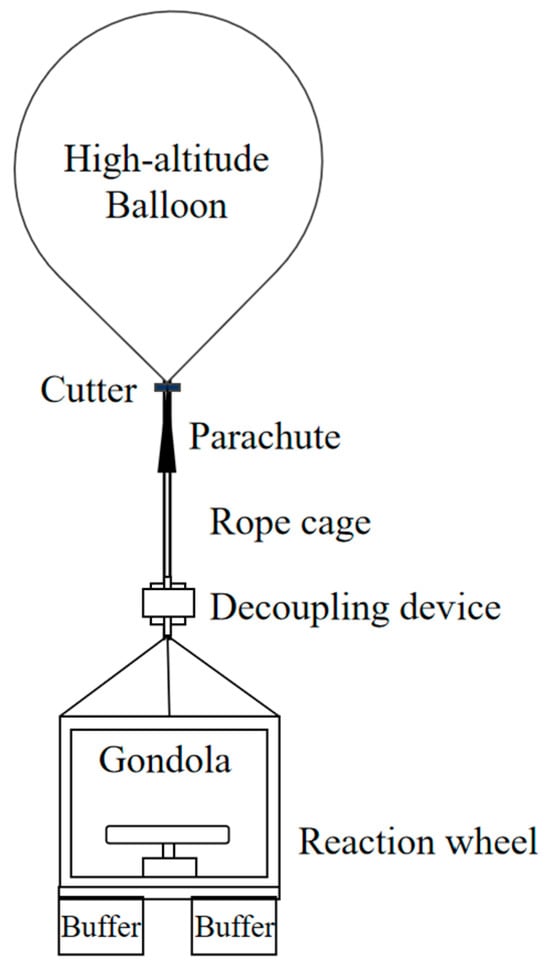
Figure 1.
Schematic diagram of high-altitude scientific balloon system.
2.1. Balloon and Wind Field Modeling
High-altitude scientific balloons rely on lightweight gases (e.g., hydrogen) to achieve ascent and sustained hovering. The atmosphere has different densities at different altitudes, where higher altitudes correspond to lower atmospheric densities. Therefore, during ascent, the volume of the balloon continuously expands continuously as the atmospheric density decreases, as shown in Figure 2.
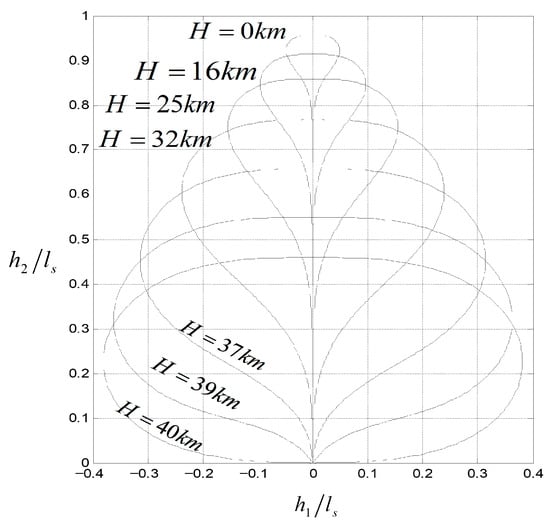
Figure 2.
Balloon Launch Shape Variation Diagram.
Due to the balloon’s incomplete expansion, it is subjected to irregular wind-induced forces—a combination that causes the balloon to rotate rapidly. The direction of this rotation generally remains unchanged [14]. However, during high-altitude suspension flight, slight airflow turbulence causes uneven wind pressure on the balloon’s surface, generating random forces that induce slow rotation of the balloon. This slow rotational motion is non-constant, with a variation cycle of approximately several minutes [15]. The data related to the rotation of the high-altitude gondola observed after the balloon was released showed that during the ascent process, the airflow changed significantly near 15 km altitude, and the angular velocity reached 1.5 r/min. During high-altitude horizontal flight of the gondola, its angular velocity was approximately 0.1 r/min, occasionally dropping to 0.01 r/min [16].
Wind disturbance is the primary external disturbance encountered in balloon motion control. As a macroscopic manifestation of the combined effects of various physical mechanisms such as atmospheric turbulence and temperature gradients, the randomness of wind disturbance has been verified by a large amount of observational data. Balloon angular velocity, induced by wind disturbance, also exhibits randomness, and the use of stochastic system theory to describe this uncertainty conforms to physical laws. The memoryless property of the first-order Markov process greatly simplifies the calculation of state transition probabilities, enabling real-time state estimation and prediction.
As an inertial system, the variation in the angular velocity of a high-altitude scientific balloon exhibits a certain memory characteristic. Over a short time scale, this memory effect can be approximated as a first-order Markov property. Therefore, this section uses the first-order Markov process to model the random motion of the balloon’s angular velocity.
The statistical characteristics of balloon angular velocity variation can be described by the following parameters: the variance characteristic, which describes the intensity of the random motion of balloon angular velocity induced by wind disturbance (and usually increases with altitude); and the power spectral density, which describes the energy distribution of different frequency components.
The first-order Markov process is defined as follows: A random process x(t) is called a Markov process under the condition that the state at t0 is known and the conditional distribution of the state at t > t0 is independent of the states before t0. Its expression is:
It can be described by differential equations:
where
is defined as the Gaussian White Noise with intensity of
,
is defined as frequency, T is defined as the time constant.
The schematic diagram of the framework of differential equations is shown in Figure 3.
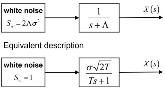
Figure 3.
Description of Random Motion Diagram of Balloon Angular Velocity.
2.2. Rope Cage Modeling
The high-altitude scientific balloon is connected to the gondola through a suspension rope. In order to increase the load-bearing capacity of the suspension rope, a rope cage composed of multiple strands of suspension ropes is often used for connection. In order to avoid the situation where the rope cage twists and contacts, causing the rope cage to intersect at a point in the middle, it is often used to add a cross support structure in the middle of the rope cage, as shown in Figure 4. This section focuses on modeling a new type of cross support rope cage.
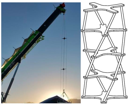
Figure 4.
Physical and schematic diagram of rope cage.
Directional channel modeling focuses on the torsional characteristics of the rope cage. Traditional modeling often uses the following simplified form to linearize the torque of the rope cage for analysis [17,18]:
where
is defined as the Twisting torque of rope cage,
is defined as the Twisting angles at both ends of the rope cage,
is defined as the Rope cage torsion coefficient. The above modeling method can simulate the torque of the rope cage well when the torsion angle of the rope cage is small. However, when the torsion angle of the rope cage is large, the simplified result may have a significant deviation from the actual situation. Therefore, in order to further characterize the nonlinear dynamic characteristics during the twisting process of the rope cage, a multi-node refined modeling approach is adopted, treating the supported parts as nodes. Each node concentrates the mass of the support and the rope cage, and the torque between nodes is composed of two parts: the rope twisting torque and the rope lifting torque.
During balloon flight, the twisting of the rope cage is mainly caused by the unequal rotational speed between the gondola and the balloon, as well as the action of the decoupling device. In the case of slow motor speed of the decoupling device, the dynamic transition process of the rope cage can be ignored. Analyze the rope cage system shown in Figure 5, where two disks are connected by hanging ropes (usually four) with a length of l. The distance between the connection points of the hanging ropes on the upper and lower disks and the center O of the disks is R1 and R2, respectively. Assuming that both disks are kept horizontal, fix the upper disk, apply a vertical downward tension F and a counterclockwise torque Ts to the lower disk, and the distance between the two disks is h.
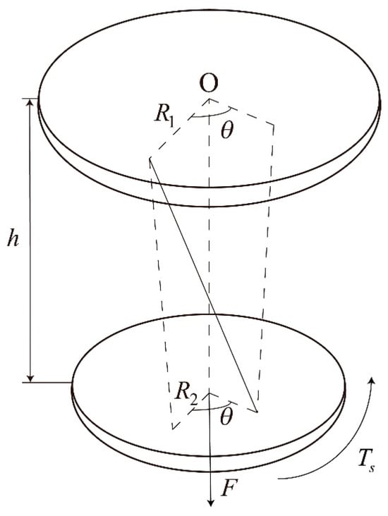
Figure 5.
Force analysis diagram of rope cage.
Give the system a virtual displacement and turn the lower disk counterclockwise by a very small angle
, so that the lower disk will have a vertical upward displacement
. According to the principle of virtual work, we can obtain:
From the geometric relationship, it can be inferred that:
Furthermore, it can be concluded that:
Combining Formulas (4)–(6), the lifting torque of the rope can be obtained as follows:
During the twisting process of the rope cage, there is still torque generated by the twisting deformation of the hanging rope itself. The twisting process is shown in Figure 6, and it can be seen that the angle of torsion of the single strand hanging rope is consistent with that of the rope cage.
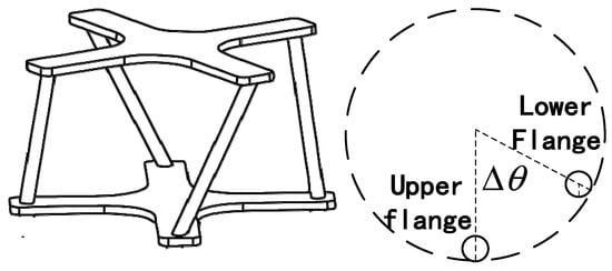
Figure 6.
Schematic diagram of rope torsion torque model.
The twisting torque of the rope can be expressed by the Feyner Schiffner equation, which takes the following form [19]:
where
,
,
is defined as the constants related to the suspension rope structure,
is defined as the rope diameter,
is defined as the tension exerted on the suspension rope,
is defined as the shear modulus of suspension rope material,
is defined as the shear modulus of suspension rope material.
The expression for
is as follows:
where
is defined as the twisting angles at both ends of the rope cage,
is defined as the rope length.
The first term of the equation
is a constant that calculates the torque at zero rotation. The second item
is to modify the torque response based on the degree of torsion of the rope, which is empirically determined from the rope torsion test data. The third term
is the torsional stiffness term, which relates torque to the geometric characteristics of the rope. The number of hanging ropes for a general cross rope cage is four, and the twisting torque of the ropes can be obtained as follows:
In summary, the moment between the nodes of the rope cage can be expressed by the following formula:
2.3. Gondola Dynamics Modeling
Assuming the moment of momentum of the gondola (including static reaction wheel) is
, the moment of inertia of the gondola relative to its own system is
, the moment of momentum of the reaction wheel when it rotates relative to its static state is
, the moment of inertia of the reaction wheel relative to its body is
, the angular velocity of the gondola is
, the rotational angular velocity of the reaction wheel relative to the gondola is
. The total moment of momentum of the gondola reaction wheel system can be expressed by the following formula:
According to the theorem of moment of momentum, it can be concluded that:
where T is the external torque, subscript I represents the inertial coordinate system, and subscript B represents the coordinate system of the gondola body.
Combining the above Equations (12) and (13), the attitude dynamics equation expressed on the gondola system is obtained as:
When the rotation axis of the reaction wheel is parallel to the azimuth axis of the gondola, that is
, it can be obtained that:
Equation (15) is simplified as:
The scalar form of the above equation is
3. Perform Structural Design and Modeling
During the suspension of high-altitude scientific balloons, energy is supplied by storage batteries, so the motors used are generally DC motors [20]. The reaction wheel and the simplified decoupling mechanism are both driven by motors. There are two types of motor driving methods, one is the direct drive method using a torque motor, and the other is the indirect drive method using a torque motor and a reducer. The prerequisite of high-precision gondola azimuth control is the precise control of the motors’ speed. Therefore, torque motors are selected for direct drive, which shortens the transmission chain, avoids gear clearances and dead zones, and easily achieves good control accuracy.
3.1. Reaction Wheel and Motor
Unlike the torque gyro driving method that generates control torque by changing the direction of momentum, the reaction wheel driving method mainly generates control torque by changing the magnitude of the momentum vector, which can be expressed as:
The design of the reaction wheel system depends on the requirements of the gondola and azimuth control system. The maximum moment of momentum requirement
of the gondola system is determined by the gondola inertia
and the gondola maximum angular velocity
, which can be expressed as:
The maximum moment of momentum requirement
of the gondola determines the inertia
of the reaction wheel and the lower limit of the maximum speed
of the reaction wheel:
When the reaction wheel reaches its maximum moment of momentum from zero, the energy it needs to absorb is:
It can be known from the formula that when
is given, the smaller
is, the greater the energy demand is, and the larger
is. Therefore, increasing
helps to reduce the energy supply of the reaction wheel motor and decrease
. The
within an appropriate range can enable the reaction wheel to have a reasonable speed regulation range, take into account the response performance of the reaction wheel motor, and facilitate quickly keeping up with the command speed. The flywheel structure diagram is shown in Figure 7.
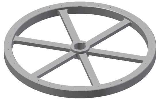
Figure 7.
Reaction wheel structure diagram.
The reaction wheel is driven by a brushless DC (BLDC) motor. Since precise speed control is required for the reaction wheel’s angular momentum exchange, and given the accuracy and response speed demands of speed control, a dual closed-loop control mode (comprising an outer speed loop and an inner current loop) is adopted for the reaction wheel motor. By leveraging the high precision of speed control and the high response speed of current control, the dual closed-loop mode can effectively enhance the control performance of the reaction wheel motor drive subsystem. Based on the dynamic equilibrium equation of the motor armature circuit, the corresponding dynamic equations are shown in Formulas (22)–(24):
where
is defined as the motor winding voltage,
is defined as the motor winding current,
is defined as the equivalent resistance of motor windings,
is defined as the equivalent inductance,
is defined as the reaction wheel motor back electromotive force constant,
is defined as the motor speed feedback,
is defined as the motor output torque,
is defined as the bearing static friction torque,
is defined as the reaction wheel rotational speed,
is defined as the flange angular velocity,
is defined as the gondola angular velocity,
is defined as the reaction wheel moment of inertia.
From the above formula, the dual closed-loop control framework diagram is as shown in Figure 8:
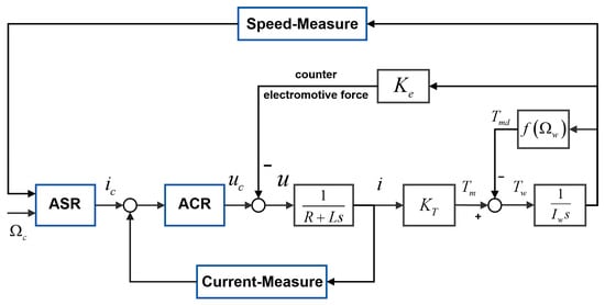
Figure 8.
Speed closed-loop + torque inner loop control mode.
Both the current loop and the speed loop adopt the PID control algorithm. The current loop, as the inner loop of the brushless DC motor control system, is mainly affected by the motor’s electromagnetic parameters. The speed loop, as the outer loop, is mainly affected by the overall mechanical performance.
3.2. Simplified Decoupling Mechanism
Compared to traditional decoupling mechanisms, the simplified decoupling mechanism eliminates the complex torsion sensor structure and only connects the rope cages and the gondola via bearings and motors. The motor’s rotor is rigidly connected to the flange, and the motor’s stator is fixed at the bottom of the cylindrical housing. The simplified decoupling mechanism adopts a decoupling control system design that uses current feedback instead of torque feedback. The structural diagram is shown in Figure 9.
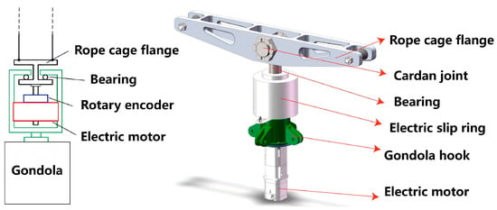
Figure 9.
The structure diagram and model diagram of the simplified decoupling mechanism.
There is an approximate relationship between the torque and current of a DC motor as follows:
The dynamic balance relationship and structural mechanics relationship of the motor armature circuit are shown in Equations (26)–(28):
where
is defined as the motor winding voltage,
is defined as the motor winding current,
is defined as the equivalent resistance of motor windings,
is defined as the equivalent inductance,
is defined as the reaction wheel motor back electromotive force constant,
is defined as the motor speed feedback,
is defined as the motor output torque,
is defined as the bearing static friction torque,
is defined as the reaction wheel rotational speed,
is defined as the flange angular velocity,
is defined as the gondola angular velocity,
is defined as the flange moment of inertia.
The model diagram of the simplified decoupling control system can be obtained from the formula, as shown in Figure 10.
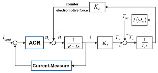
Figure 10.
The torque control of simplified decoupling motor.
4. System Control Design
The azimuth control system of the balloon-borne gondola incorporates two main functions: namely, azimuth control and decoupling control. Azimuth control generates a command speed for the reaction wheel based on the deviation between the gondola’s actual and desired azimuths. This drives the reaction wheel to adjust its angular momentum and generate control torque to steer the gondola toward the desired azimuth. Decoupling control serves two primary functions: one is to eliminate the disturbance torque transmitted by the suspension ropes, which is caused by the relative rotation between the gondola and the balloon; the other is to mitigate angular momentum accumulation by balancing the total angular momentum of the reaction wheel and the gondola. This avoids the accumulation of the reaction wheel’s speed and prevents it from reaching speed saturation (which would result in loss of control capability) [21,22].
The system control includes two control loops, namely the gondola azimuth control loop and the decoupling control loop. The system control structure diagram is shown in Figure 11. The basic information is shown in Table 1.
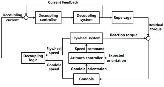
Figure 11.
System Control Structure Diagram.

Table 1.
Basic information of control loop.
4.1. Directional Control Design
According to the model in Section 2.3, assuming that pitch and roll do not rotate, the mathematical model of the reaction wheel azimuth control channel can be expressed as:
Formula (29) integration yields:
Organize and obtain:
The azimuth control adopts PID algorithm, which can take the reaction wheel speed as the corresponding azimuth angle processing value:
Substitute into Formula (30) to obtain:
Order
From Formula (34), it can be seen that the right-hand side of the equation is a constant, while the left-hand side is a second-order system. By selecting reasonable PID parameters, corresponding characteristics can be obtained. When
, the system convergence can be guaranteed.
4.2. Decoupling Control Design
During the suspension process of high-altitude scientific balloons, various disturbances will occur, causing the reaction wheel speed to continuously increase and eventually enter a saturation state. The most common constant disturbance torque is mainly the effect of bearing friction on the nacelle. The balloon rotates, driving the rope cage to twist. With bearings, the friction force of the bearings ultimately acts on the gondola, but the friction force has complex motion characteristics and cannot be directly measured.
Therefore, this section does not directly measure the external interference torque. Instead, a dynamic decoupling algorithm based on the angular momentum theorem is designed to predict the interference: by using the angular momentum of the gondola reaction wheel system, the cumulative effect of the interference torque acting on the gondola reaction wheel system is inferred, and then the effect of the external interference torque is offset by the decoupling motor.
According to the conservation theorem of angular momentum, the angular momentum of the gondola reaction wheel system can be expressed by the following formula:
Stable tracking under ideal conditions
,
, At time t, the total deviation of the reaction wheel angular momentum of the gondola can be expressed by the following formula:
Assuming that there is an external torque
acting from time t0 to time t1, the incremental angular momentum of the gondola reaction wheel can be expressed as:
where
is defined as the angular velocity of the reaction wheel at time t0,
is defined as the gondola angular velocity at time t0,
is defined as the gondola angular velocity at time t1. By using the PID algorithm and combining it with Formula (36) and (37), the decoupling algorithm for the decoupling motor can be obtained:
At the same time, in order to avoid repeated operation of the decoupling motor, a dead zone link is set, and decoupling control is not performed within the range of
dead zone.
5. Algorithm Optimization Design
In the previous section of system control design, PID algorithm was used. The traditional PID control algorithm has become one of the most widely used feedback control algorithms in the field of automatic control due to its strong adaptability and ease of adjustment and optimization [23]. But it has the following disadvantages [24]:
(1) The initial error is large, which can easily cause excessive overshoot during the tracking phase;
(2) PID linear combination is not the optimal solution and cannot suppress minor disturbances in a timely manner during the stable control phase.
Therefore, in this section, a differential tracker is designed for the tracking phase to avoid excessive overshoot; design a neural network PID algorithm to improve pointing accuracy during the stable control phase.
5.1. Nonlinear Differential Tracker
The azimuth control adopts PID control, and the integration link is large. If the initial azimuth angle of the gondola is significantly different from the target azimuth angle, it is easy to cause the reaction wheel to saturate and overshoot to occur when approaching the target. In order to ensure smooth maneuvering of the gondola and further optimize the maneuvering algorithm, a nonlinear tracking differentiator is introduced, and the azimuth tracking transition process can track the input signal as smoothly as possible to obtain an approximate derivative of the input signal.
Assuming a second-order differential equation:
For selecting the fast optimal control synthesis function for
, there are:
The above nonlinear differential tracker achieves smooth and overshoot free tracking of the input signal, and by changing the size of r, the tracking speed can be controlled. At the same time, the gondola has a maximum speed limit of
; therefore, the expression for the speed limiting nonlinear differential tracker applicable to the azimuth control system is:
Modeling and simulation of nonlinear differential tracker and rate limiting nonlinear differential tracker yields tracking curves:
As shown in Figure 12, the nonlinear differential tracker has good tracking performance, smooth transition process, and the speed limiting nonlinear tracker can meet the maximum speed limit requirement of the gondola azimuth control.
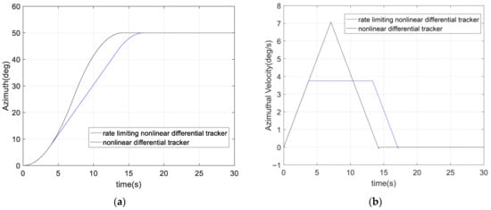
Figure 12.
(a) Nonlinear Tracker and Speed Limiting Nonlinear Tracker Tracking Curve; (b) Nonlinear Tracker and Speed Limiting Nonlinear Tracker Angular Rate Curve.
5.2. Neural Network PID Algorithm
In this section, a neural network PID control algorithm is designed to further improve the control accuracy during the phase of enhancing the stability control of the gondola’s azimuth. The neural network PID controller structure consists of an input layer, a hidden layer, and an output layer. The input layer has 4 nodes, select the difference a between the commonly used set value and the actual value
, the rate of change b of the error, the acceleration c of the error change, and the bias term constant 1 that helps improve the network fitting ability as inputs:
The hidden layer has 5 nodes, and the activation function selects the positive and negative symmetric Sigmoid function, which can map the entire range of inputs to outputs between −1 and 1, helping to enhance the nonlinear processing capability of the network. The output layer has three nodes, corresponding to the three parameters kp, ki, and kd in the PID. The hidden layer nodes are connected to the input layer nodes, output layer nodes, and hidden layer nodes through weights, and each hidden layer node also has a threshold. These weights and thresholds are updated during the training process using backpropagation algorithm. The number of output layer nodes is 3, corresponding to the three parameters kp, ki, and kd in the PID. The schematic diagram of the neural network PID structure is shown in Figure 13. The PID control based on Neural Network is shown in Figure 14.
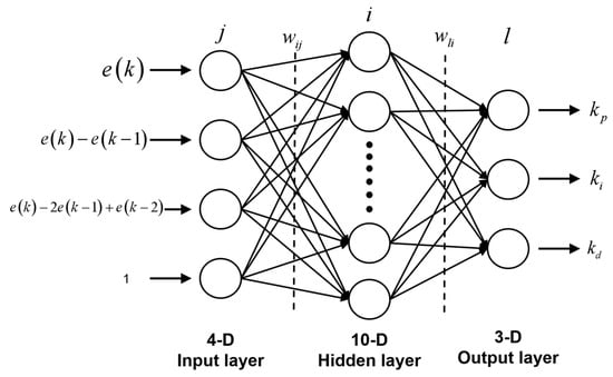
Figure 13.
Schematic diagram of Neural network PID structure.
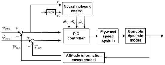
Figure 14.
PID Control Based on Neural Network.
The basic idea of error backpropagation is to adjust the connection weights between the input layer and the hidden layer, as well as between the hidden layer and the output layer, by calculating the error between the current value of the control variable and the target value, in order to change the output value of the neural network. Through repeated iterations, the error is continuously reduced, thus continuously approaching the target value. The BP neural network PID uses the square of the control target error value as the loss function, as shown in Equation (43).
Using gradient descent strategy, adjust the connection weights in the negative gradient direction of the target, taking the weight adjustment from the output layer to the hidden layer as an example:
where xite is defined as the learning rate, e(k) is defined as the current error, uk is defined as the control variable, which is the output value of the PID controller, kj is the jth parameter in the PID controller, and oj is the input value of the jth neuron in the output layer. The specific values of each parameter in the equation can be obtained from Equation (46)–(49).
6. Simulation Verification
6.1. No Directional Control
In the case of no directional control, the simulation adopts the first section directional channel model, which is modeled and simulated through Simulink. The rope cage is modeled using 5-node simulation, and the model is shown in the following Figure 15.

Figure 15.
Directional channel motion model.
Using the parameters of the gondola in Appendix A, the model was run for 300 s, and the simulation of the balloon gondola is shown in the following Figure 16:
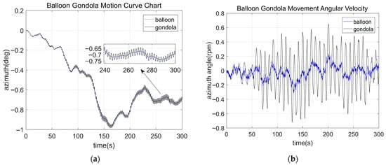
Figure 16.
(a) Balloon Gondola Motion Curve Chart; (b) Balloon Gondola Movement Angular Velocity.
The balloon rotates under external force and is driven by the rope cage to rotate the gondola. The gondola rotation is a combined motion of balloon rotation and rope cage oscillation. Spectral analysis is conducted on the motion of balloons and gondolas, and Fourier transform is used to obtain the analysis results by taking the logarithm (log10) of the amplitude, as shown in Figure 17:
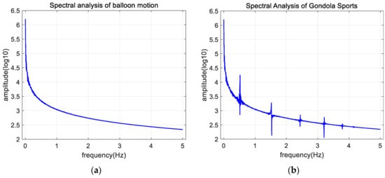
Figure 17.
(a) Spectral analysis of balloon motion; (b) Spectral Analysis of Gondola Sports.
From the analysis of the motion spectrum of the balloon gondola, it can be seen that the balloon spectrum conforms to the random motion designed by the model. According to the frequency spectrum analysis of the gondola, there are five oscillation modes corresponding to five nodes on the basis of balloon motion. The motion modes of the gondola are shown in the following Table 2:

Table 2.
Gondola motion mode.
6.2. Algorithmic Control
Establish a Simulink simulation model based on the modeling of the azimuth channel in Section 1, controller design in Section 2, and system control design in Section 3, as shown in Figure 18.
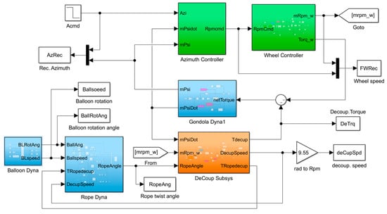
Figure 18.
Model of balloon-borne gondola azimuth control system.
Using the parameters of the gondola azimuth control system in Appendix A, and setting PID parameters (kp = 100, ki = 50, kd = 60), set the initial target to 100°, switch to target 50° after 100 s, and then move for another 100 s. The results of running the model are shown in the following Figure 19:
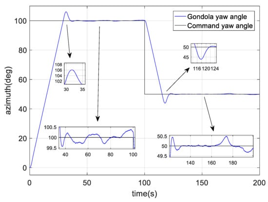
Figure 19.
Gondola azimuth motion curve based on PID control.
From Figure 19, it can be seen that there is a significant overshoot, with an overshoot size of 6°, indicating a control accuracy of <0.5°. It can be seen that PID control is not sufficient to fully utilize the performance of the controller, so it is necessary to optimize the controller design.
Using the nonlinear differential tracker and variable gain PID control in Section 4, the simulation modeling is shown in the following Figure 20:
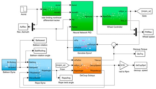
Figure 20.
Control System of Ball Load Gondola Based on Nonlinear Differential Tracker and Neural Network PID Control.
Set the initial target to 100°, switch to target 50° after 100 s, and then move for another 100 s. Run the simulation model, and the simulation results are shown in the following Figure 21:
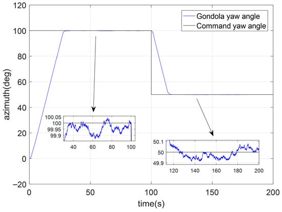
Figure 21.
Gondola azimuth motion curve based on Nonlinear Differential Tracker and Neural Network PID Contro.
From Figure 21, it can be seen that the attitude control tracking phase of the gondola has a smooth start, uniform rotation, and minimal overshoot when entering the stable phase, with a stable control accuracy of <0.1°. Spectral analysis is conducted on the stable state of the gondola motion, and Fourier transform is used to obtain the spectrum analysis of gondola motion, as shown in Figure 22:
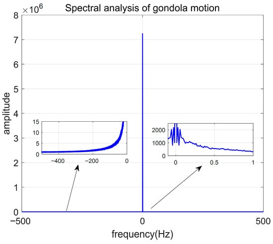
Figure 22.
Spectrum analysis diagram of gondola motion.
It can be seen that the azimuth control system of the balloon-borne gondola successfully decouples the rotation of the balloon and suppresses various modal interferences of the rope cage motion. Multiple experiments were compared and analyzed, with targets set at 40°, 60°, 80°, and 100° for multiple simulation experiments. The simulation step size was 0.001 s, and each simulation time was 200 s. The error was evaluated using the ISE formula, and the 100 s error after the first occurrence of
(
) was extracted. The formula is as follows:
The simulation results are shown in the following Table 3:

Table 3.
Four experimental stages IAE.
From Table 3, it can be seen that in terms of IAE indicators, neural network PID is one order of magnitude lower than traditional PID, demonstrating significant performance advantages. In terms of steady-state error indicators, neural network PID is 64.8% lower than traditional PID, indicating that the performance of neural network PID control is much better than traditional PID control.
7. Conclusions
This study proposes a new solution for the near-space balloon-borne azimuth control system, and the main achievements are as follows:
(1) Adopting a multi-node nonlinear modeling method for the rope cage can more accurately characterize the torsional motion characteristics of the rope cage;
(2) Systematically modeling the azimuth channel to more fully reveal the motion mode of the balloon-borne gondola;
(3) Designing a new system control scheme based on a simplified decoupling mechanism and reaction wheel;
(4) Designing a neural network PID control algorithm based on nonlinear differential tracker, which can achieve stable control accuracy <0.1° and effectively suppress the original motion modes;
This study provides a new design scheme for the azimuth control system of the balloon-borne gondola. Through systematic modeling, design, and simulation verification, it fully demonstrates that the scheme can still achieve the same azimuth accuracy control even with simplified execution mechanism. This research achievement provides important reference for improving the azimuth control performance of the balloon-borne platform and can serve the astronomical observation and ground observation tasks of the balloon-borne platform, with broad application prospects.
Author Contributions
Conceptualization, Y.L.; Methodology, Y.L.; Software, Y.L.; Validation, Y.L.; Formal analysis, X.Z.; Writing – original draft, Y.L.; Writing – review & editing, J.Z. and X.Z.; Supervision, J.Z.; Project administration, J.Z. All authors have read and agreed to the published version of the manuscript.
Funding
The research is funded by National Natural Science Foundation of China, 52227811. The article processing charge was funded by the Aerospace Information Research Institute, Chinese Academy of Sciences.
Data Availability Statement
The original contributions presented in the study are included in the article, further inquiries can be directed to the corresponding author.
Conflicts of Interest
The authors declare no conflict of interest.
Appendix A
The simulation parameters of the balloon-borne gondola attitude control system used in this article are shown in the following table.

Table A1.
System simulation parameter table.
Table A1.
System simulation parameter table.
| Parameter Type | Symbol | Value | Unit |
|---|---|---|---|
| Moment of inertia of the gondola | 160 | kg·m2 | |
| Reaction wheel moment of inertia | 2 | kg·m2 | |
| Flange moment of inertia | 0.6 | kg·m2 | |
| Rope cage torsional stiffness | 1.924 | kg·m2 | |
| Reaction wheel motor resistance | 3.4 | ||
| Reaction wheel motor inductance | 6.8 × 10⁻³ | ||
| Reverse electromotive force coefficient of reaction wheel motor | 1.6 | V/(rad/s) | |
| Torque coefficient of reaction wheel motor | 1.47 | N·m·A | |
| Rated voltage of reaction wheel motor | 24 | V | |
| Rated current of reaction wheel motor | 7 | A | |
| Locking torque of reaction wheel motor | 10 | N·m | |
| Reverse twist motor resistor | 4.74 | ||
| Inductance of simplified decoupling motor | 9.48 × 10⁻³ | ||
| Reverse electromotive force coefficient of simplified decoupling motor | 1.6 | V/(rad/s) | |
| Torque coefficient of simplified decoupling motor | 1.72 | N·m·A | |
| Rated voltage of simplified decoupling motor | 24 | V | |
| Rated current of simplified decoupling motor | 5 | A | |
| Anti-twist motor stalling torque | 3 | N·m |
References
- Huang, W.N.; Zhang, X.J.; Li, Z.B.; Wang, S.; Huang, M.; Cai, R. Development Status and Application Prospect of Near Space Science and Technology. Sci. Technol. Rev. 2019, 37, 46–62. [Google Scholar]
- Smith-Pierce, M.C.; Charoenboonvivat, Y.C.; Shukla, D.; Komerath, N.M. High Altitude Aerodynamic Reflectors to Counter Climate Change. In Proceedings of the 2018 Applied Aerodynamics Conference, New York, NY, USA, 25–29 June 2018; AIAA: Reston, VA, USA, 2018; p. AIAA2018-3963. [Google Scholar]
- Yajima, N.; Imamura, T.; Izutsu, N.; Abe, T. Scientific Ballooning: Technology and Applications of Exploration Balloons Floating in the Stratosphere and the Atmospheres of Other Planets; Springer Science & Business Media: New York, NY, USA, 2009. [Google Scholar]
- Ehrenfried, D.V. Stratospheric Balloons: Science and Commerce at the Edge of Space; Springer: New York, NY, USA, 2021. [Google Scholar]
- Jones, W.V. Evolution of Scientific Ballooning and Its Impact on Astrophysics Research. Adv. Space Res. 2014, 53, 1405–1414. [Google Scholar] [CrossRef]
- Li, Y.J.; Huang, W.N.; Zhou, J.H.; Zhang, X.; Zhang, H. Development Status and Prospects of Near-Space Observatories. Chin. J. Space Sci. 2024, 44, 1068–1085. [Google Scholar] [CrossRef]
- Yajima, N.; Kokaji, S.; Hashino, S. Report of Mechanical Engineering Laboratory No. 135; ISAS: Sagamihara City, Japan, 1986. [Google Scholar]
- Ye, X.M. Study on High-Accuracy Attitude Control and Pointing Technology of a Large Balloon-Borne Solar Telescope. Ph.D. Thesis, National Astronomical Observatories, Chinese Academy of Sciences, Beijing, China, 1999. [Google Scholar]
- Shoji, Y.; Taguchi, M.; Nakano, T.; Maeda, A.; Imai, M.; Gouda, Y.; Watanabe, M.; Takahashi, Y.; Sakamoto, Y.; Yoshida, K. FUJIN-2: Balloon-Borne Telescope for Optical Observation of Planets. Trans. Japan Soc. Aeronaut. Space Sci. Aerosp. Technol. Japan 2016, 14, Pk_95–Pk_102. [Google Scholar] [CrossRef] [PubMed]
- Tucker, G.S.; Ade, P.A.R.; Bock, J.J.; Devlin, M.; Griffin, M.; Gundersen, J.; Halpern, M.; Hargrave, P.; Hughes, D.; Klein, J.; et al. The Balloon-Borne Large Aperture Sub-Millimeter Telescope. Adv. Space Res. 2004, 33, 1793–1796. [Google Scholar] [CrossRef]
- Solanki, S.K.; Riethmüllert, L.; Barthol, P.; Danilovic, S.; Deutsch, W.; Doerr, H.-P.; Feller, A.; Gandorfer, A.; Germerott, D.; Gizon, L.; et al. The Second Flight of the Sunrise Balloon-Borne Solar Observatory: Overview of Instrument Updates, the Flight, the Data, and First Results. Astrophys. J. Suppl. Ser. 2017, 229, 2–16. [Google Scholar] [CrossRef]
- Wang, H.H.; Yuan, Z.H.; He, C.A. Design of Comprehensive Decoupler for Balloon-Borne Gondola’s Azimuth Control. In Proceedings of the Chinese Control Conference (CCC), Xi’an, China, 26–28 July 2013. [Google Scholar]
- Zhang, D.W.; Zhou, J.H.; Huang, W.N. A Simplified Design of Decoupling Control System in Balloon Gondola. Aerosp. Control 2016, 34, 76–82. [Google Scholar]
- Liao, J.; Yuan, J.J.; Jiang, Y.; Yang, Z.; Li, J.; Lu, Z.; Wu, C.; Wang, N. Study on Motion Characteristics of High-Altitude Zero-Pressure Balloons During Ascent. Aerosp. Return Remote Sens. 2019, 40, 11–19. [Google Scholar]
- Wang, H.H. Study on Design Technology and Autonomous Attitude Control Method of Balloon-Borne Gondola Platform. Ph.D. Thesis, Northwestern Polytechnical University, Xi’an, China, 2014. [Google Scholar]
- Barabash, V.; Ivanov, D.; Ovchinnikov, M.; Tkachev, S.S. Balloon Payload Attitude Control System; Keldysh Institute Preprints: Moscow, Russia, 2010; pp. 4–6. [Google Scholar]
- Li, Y.J.; Zhou, J.H.; Zhang, X.J. Dynamics modeling and parameter identification for azimuth channel of balloon-gondola system. J. Beijing Univ. Aeronaut. Astronaut. 2024, 50, 2001–2008. [Google Scholar]
- Wang, H.H.; Yuan, Z.H.; Chen, Q. Study on Azimuth Control of Stratospheric Balloon-Borne System Based on Adaptive PID. In Proceedings of the 29th Chinese Control Conference, Beijing, China, 29–31 July 2010; Beihang University Press: Beijing, China, 2010; pp. 2209–2213. [Google Scholar]
- Bradon, J.; Ridge, I.; Chaplin, R. Modelling the Torsional Interaction of Wire and Polyester Fibre Ropes Used for Offshore Moorings. Proc. Inst. Mech. Eng. Part M J. Eng. Marit. Environ. 2005, 219, 163–172. [Google Scholar] [CrossRef]
- Cai, M.Y.; He, C.A. Simulation Study on Attitude Control System of Balloon Gondola. Comput. Simul. 2005, 22, 56–59. [Google Scholar]
- Zhang, D.W.; Zhou, J.H.; Huang, W.N. Design of simplified reaction torque control system for high-altitude balloon gondola attitude control. Aerosp. Control. 2016, 34, 76–82. [Google Scholar]
- Li, Y.J. Research on Attitude Control Technology of Balloon-Borne Gondola Based on Multi-Sensor Combination. Ph.D. Thesis, University of Chinese Academy of Sciences, Beijing, China, 2023. [Google Scholar]
- Bennett, S. The Past of PID Controllers. Annu. Rev. Control 2001, 25, 43–53. [Google Scholar] [CrossRef]
- Meshram, P.M.; Kanojiya, R.G. Tuning of PID Controller Using Ziegler-Nichols Method for Speed Control of DC Motor. In Proceedings of the IEEE International Conference on Advances in Engineering, Science and Management (ICAESM-2012), Nagapattinam, India, 30–31 March 2012; IEEE: New York, NY, USA, 2012; pp. 117–122. [Google Scholar]
Disclaimer/Publisher’s Note: The statements, opinions and data contained in all publications are solely those of the individual author(s) and contributor(s) and not of MDPI and/or the editor(s). MDPI and/or the editor(s) disclaim responsibility for any injury to people or property resulting from any ideas, methods, instructions or products referred to in the content. |
© 2025 by the authors. Licensee MDPI, Basel, Switzerland. This article is an open access article distributed under the terms and conditions of the Creative Commons Attribution (CC BY) license (https://creativecommons.org/licenses/by/4.0/).