Abstract
This paper presents the development of an airport bipolar DC microgrid and its interconnected operations with the utility grid, electric vehicle (EV), and more electric aircraft (MEA). The microgrid DC-bus voltage is established by the main sources, photovoltaic (PV) and fuel cell (FC), via unidirectional three-level (3L) boost converters. The proposed one-cycle control (OCC)-based current control scheme and quantitative and robust voltage control scheme are proposed to yield satisfactory responses. Moreover, the PV maximum power point tracking (MPPT) with FC energy-supporting approach is developed to have improved renewable energy extraction characteristics. The equipped hybrid energy storage system (HESS) consists of an energy-type battery and a power-type flywheel; each device is interfaced to the common DC bus via its own 3L bidirectional interface converter. The energy-coordinated operation is achieved by the proposed droop control. A dump load leg is added to avoid overvoltage due to an energy surplus. The grid-connected energy complementary operation is conducted using a neutral point clamped (NPC) 3L three-phase inverter. In addition to the energy support from grid-to-microgrid (G2M), the reverse mcrogrid-to-grid (M2G) operation is also conductible. Moreover, microgrid-to-vehicle (M2V) and vehicle-to-microgrid (V2M) bidirectional operations can also be applicable. The droop control is also applied to perform these interconnected operations. For the grounded aircraft, bidirectional microgrid-to-aircraft (M2A)/aircraft-to-microgrid (A2M) operations can be performed. The aircraft ground power unit (GPU) function can be preserved by the developed microgrid. The MEA on-board facilities can be powered by the microgrid, including the 115 V/400 Hz AC bus, the 270 V DC bus, the switched-reluctance motor (SRM) drive, etc.
1. Introduction
As generally recognized, the use of microgrids [1], EVs [2,3], and more-electric aircraft (MEA) [4] can effectively reduce fossil energy consumption and thus carbon-dioxide emissions. All these plants have been gradually promoted and demonstrated effectiveness. Microgrids [5,6,7,8,9,10,11] using renewable sources (RESs) can be independently operated from the utility grid to reduce the traditional generation burden. Basically, a DC microgrid can be established using unipolar or bipolar DC bus [10,11]. The latter possesses some merits, such as having line fault-tolerant capability, a larger transmission capacity, simpler load converter schematics, etc. The bipolar DC-bus is adopted for the developed airport microgrid for reliability reasons. Till now, there were many existing examples of microgrids [12,13,14].
Airport microgrids employing RES can increase power-support resilience and reliability and also achieve environmentally friendly purpose. However, less research and existing airport microgrids have been seen until now. Although some applications of PV and/or energy storage devices in airports are found [15,16,17], systematic and complete airport microgrids are still rare. The slow progress being achieved is perhaps due to reliability concerns, conservative thinking, more strict requirements, a lack of related regulations and standards to follow [15], etc. An experimental airport DC microgrid is developed in this paper, and the related key technologies of schematic and control schemes are developed. These developed approaches are unified and can be directly applied to practical large-scale microgrids.
The most commonly used RESs, perhaps, are PV and wind generators. As to the distributed generators (DGs), FC [18,19,20] and micro turbine generators are the two typical ones. For the FC, although cost and maintenance are still the key factors affecting its popularization progress, the zero-emission new energy source possesses the application potential in transportation EVs and the future all electric aircraft (AEA) [20]. As far as the safety issue is concerned, PV combined with FC will be the better choice and will be adopted in the developed airport microgrid.
For the possible microgrid input sources, the PV output power is unpredictable, unstable, and even totally elapsed at night. As to the FC, its generated output also fluctuates. Hence, the equipment of suited energy storage devices [21,22] is indispensable for enhancing the power supply quality. The HESS, consisting of an energy-type battery [23,24] and a power-type FW [25,26,27], is adopted in the developed microgrid. Moreover, the grid-connected bidirectional operation is also feasible for further achieving uninterruptable power supply to airport facilities.
To increase the resilience and reliability of the airport microgrid power system, grid-connected operation via a bidirectional inverter is needed [11]. As the energy deficiency occurs, the energy supplementary support can be seamlessly provided from the utility grid. Conversely, the surplus energy from microgrids can be sent back to the grid for electricity bill compensation. EVs [28,29,30,31] with on-board batteries can be regarded as movable energy storage plants and arranged to perform grid-to-vehicle (G2V) and V2G operations [32,33,34,35,36], and vehicle-to-microgrid (V2M)/M2V operations [37]. The whole energy utilization can be more effectively enhanced. More specifically, the grounded MEA [38,39,40,41] can also conduct its interconnected operation on the airport microgrid to have similar effects. The interconnected operations of both EV and MEA are presented in this paper. The ground power unit’s powering functions can be preserved. The MEA electric power architecture (EPA) with high-voltage common DC-buses developed in [40,41] is employed to conduct the M2A/A2M operations of the established dedicated airport microgrid to the landed MEA. The MEA on-board facilities can be powered from the microgrid with the same functions as the traditional movable GPU.
All harvested sources, loads, energy storage devices, EVs, MEAs, and utility grids must be interfaced to the microgrid via proper power converters and controls. Some commonly used converters are surveyed in the literature [42,43,44]. For the bipolar DC microgrid, the 3L converters with inherent bipolar output are preferable [45,46,47,48]. As to the AC sources, such as AC motor-driven FW and utility grid, bidirectional inverters are adopted [49,50,51]. Except for the schematic and their control schemes, the coordinated control between the constituted power stages is critical in achieving better energy transfer and managing characteristics for a microgrid system. The typical control approaches can be referred to [5,6,7,52,53,54,55]. In the developed microgrid, the droop control method is applied to the current sharing control between the battery and the flywheel and also to the M2G/G2M operations.
An experimental airport bipolar DC microgrid is developed in this paper. Its interconnected operations with the utility grid, EVs, and MEA are also presented. All the constituted components are interfaced to the common DC-bus via various 3L converters. The DC-bus voltage is established by PV and FC with the proposed power distributed control. The equipped HESS consists of a battery and a flywheel using droop control to conduct the energy coordinated operation. The interconnected operations of the developed airport microgrid include: (i) G2M and M2G bidirectional operations; (ii) isolated bidirectional M2V and V2M operations using a 3L CLLC converter; and (iii) bidirectional operations between the microgrid and the grounded aircraft. All the established power stages and operation modes are evaluated by measured results.
2. System Configuration
Figure 1 shows the system configuration of the developed airport DC microgrid, and the detailed power circuit is depicted in Figure 2. The major features and functions of the developed airport microgrid are briefly described as follows:
- (1)
- The DC-bus bipolar-voltage is established by the PV and the FC via unidirectional 3L boost DC-DC converters. PV is more appropriate renewable source for airports due to the special terrain limitations, while the zero-emission new energy device FC possesses the future application potential. The coordinated control scheme is proposed for the renewable PV source with MPPT and the distributed FC source, providing energy support to yield enhanced power generation characteristics. Well-regulated bus voltage is preserved by the designed controller. An OCC-based current control scheme and a robust voltage control scheme are proposed.
- (2)
- In the battery/FW HESS, the two storage devices are respectively connected to the common DC-bus via a bidirectional 3L boost converter and a bidirectional 3L three-phase switch-mode rectifier (SMR). The droop control scheme is developed to yield good current sharing characteristics between the energy-type and the power-type storage devices.
- (3)
- A chopped dump load is equipped across the DC-bus to prevent overvoltage.
- (4)
- A 3L NPC bidirectional three-phase inverter is used to conduct the G2M and M2G energy complementary operations. The droop control approach is also proposed to handle the G2M/M2G operations. The grid-connected airport microgrid can possess increased resilience and power-supply reliability.
- (5)
- The microgrid-to-vehicle (M2V) and the vehicle-to-microgrid (V2M) operations can be performed via the off-board DC fast charger or the on-board charger. The galvanic isolation is provided by the 3L CLLC resonant converter. The total energy utilization is further enhanced by considering the EV as a movable storage facility. This effectiveness is more obvious in the airport microgrid compared to the conventional microgrid.
- (6)
- As the aircraft is grounded, its bidirectional operations to microgrid can be conducted. Taking the more electric aircraft (MEA) electric power architecture (EPA) presented in [40,41] as an application example, the aircraft on-board facilities can be powered by the developed microgrid. The functions of a ground power unit are preserved. The arranged test facilities include the 115 V/400 Hz AC-bus, the 270 V DC-bus, and the example SRM drive [41]. The aircraft can also provide energy support to the microgrid.
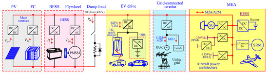
Figure 1.
System configuration of the developed airport DC microgrid.
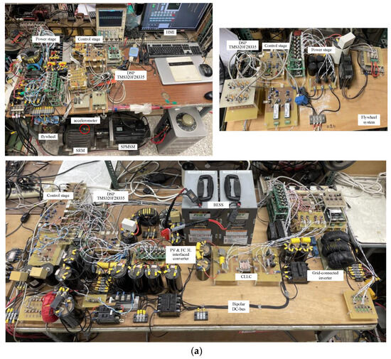
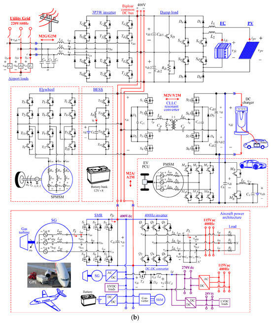
Figure 2.
The developed airport DC microgrid; (a) experimental setup photo; (b) detailed schematic.
From Figure 1 and the above descriptions, one can be aware of the obvious differences between the proposed dedicated airport microgrid and the conventional microgrid [5,6,7,8,9,10,11,12,13,14]. For an academic university laboratory, only the scale-down prototype system can be established. However, for all constituted power stages, the detailed designs of power circuits, and control schemes are presented. The presented approaches are unified and can be applied to a large-scale microgrid. Since all the established converters belong to three-level schematics, they are suited for higher-power applications.
3. The Established PV and FC-Powered Microgrid
3.1. The Adopted PV Array and FC
The employed PV array is emulated using a commercialized power supply (62100H-600S, 600 V, 17 A, 10 kW, by Chroma, Taoyuan, Taiwan). The emulated PV array P-V curves under various solar irradiances are shown in Figure 3 with labeled maximum power points (MPPs). To enhance the power-supply quality of the micro-grid, distributed FC energy support is added. The commercialized power supply is also used as the emulated FC source. Figure 4 shows the simulated voltage-current-regulated curve.
Figure 3.
Emulated output P-V curves of the employed PV array under various solar irradiances.
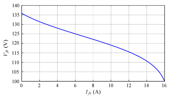
Figure 4.
The emulated FC module voltage curve.
3.2. Three-Level Boost Interface Converters
As shown in Figure 2, both PV and FC employ the uni-directional 3L boost converter to naturally establish a bipolar voltage DC bus. For example, the circuit with PV input is shown in Figure 5. The coordinated control scheme of the PV and FC systems is depicted in Figure 6. Its cascade control structure consists of an outer voltage-loop and an inner current-controlled PWM (CCPWM) scheme using the proposed one-cycle control (OCC) with PV/FC current sharing. The current commands and are yielded by the outer control loops.
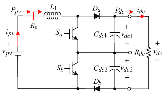
Figure 5.
Power circuit of a 3L boost converter for PV.
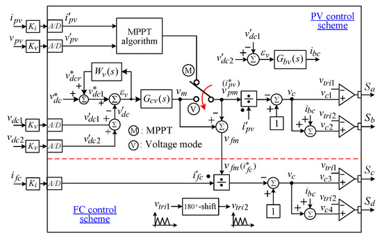
Figure 6.
The proposed coordinated control scheme for PV and FC systems.
In the case of sufficient irradiance, the PV 3LBC adopts constant voltage control, and the current control for FC is set to be zero without output power. On the contrary, when the solar power is insufficient, the control signal under MPP tracking is subtracted from to yield the to set the generation from FC. Hence, in the proposed PV/FC hybrid source system, the PV can conduct MPP tracking to extract maximum solar energy, as the irradiance is sufficient. The FC can supply the energy to the microgrid automatically when the irradiance is deficient.
3.2.1. Circuit Components
The energy storage inductor is designed for the worst-case scenario with PV input under the MPP of irradiance. The CCM operation under all conditions can be assured. The designed inductor is also employed for the FC-interfaced converter. The system variables at the chosen operating point are:
- , where the unity efficiency is assumed;
- Switching frequency
- The IGBT module SK30MLI066 by Semikron Corp. is used to form the developed 3LBC.
- Energy storage inductor
The inductor current ripple is set to guarantee the converter is in CCM operation in most cases, as follows:
where . Hence, the minimum inductance is found as . An available inductor with is employed. Accordingly, the actual inductor current ripple is calculated as .
- DC output filtering capacitor
By setting the output voltage ripple the capacitance of the output filter capacitor is found as follows:
Accordingly, capacitors are chosen to be then is yielded.
3.2.2. The Proposed OCC-Based CCPWM Scheme
Taking the PV system as an example, Figure 7 shows the proposed OCC-based CCPWM scheme. The PWM carrier embedded in the employed DSP is defined as where is the amplitude of tri-angular carrier wave.
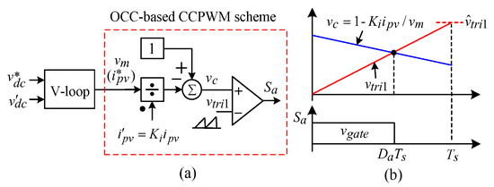
Figure 7.
The proposed OCC-based CCPWM scheme: (a) control scheme; (b) key waveforms.
Referring to Figure 5, assuming the driving point resistance of the PV source be one has:
The voltage transfer ratio of boost converter in CCM is:
From (3) and (4), one can obtain:
Equation (5) is multiplied with the current sensing factor to yield:
where denotes the current command voltage generated by the outer voltage loop.
Since from (6), the control force shown in Figure 7 can be expressed as .
Comments: From Figure 7, one can be aware that: (i) compared to the conventional ramp-comparison CCPWM scheme, the dynamic current feedback controller is not needed for the proposed control scheme; and (ii) as to the OCC scheme, the resettable integrator and flip-flop in the traditional mechanism are all not required here.
3.2.3. Bipolar Voltage Balancing Controller
As indicated in Figure 6, the voltage difference between and is regulated by a PI controller to yield the voltage balancing control signal , then is injected into the PWM control signal . The controller is set as:
3.2.4. Voltage Control Scheme
With a well-designed OCC scheme, the 3LBC voltage loop dynamic behavior can be represented by the block diagram shown in Figure 8a. The plant model is characterized by: (i) = voltage sensing factor; (ii) load power disturbance constant; and (iii) the first-order plant dynamic model:
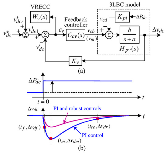
Figure 8.
The proposed voltage control scheme of 3LBC: (a) block diagram; (b) desired voltage step regulation responses.
In the proposed control scheme shown in Figure 8a, the feedback controller is augmented with the voltage robust error cancellation controller (VRECC) to yield a quantitative and robust voltage regulation response against load and input changes.
The experimental dynamic model estimation and the quantitative voltage feedback controller design are described in detail below. Moreover, a simple, robust control is proposed to enhance the voltage dynamic response and robustness.
The desired voltage response due to a step load power change is sketched in Figure 8b with the key features: (i) no overshoot and steady-state error; (ii) having the desired maximum and restore time , where is defined as ; and (iii) by adding the VRECC, the variation of regulation response can further be reduced.
(a) Voltage feedback controller
For simplicity, the PI voltage controller is chosen:
To achieve the specified response, the plant model parameters are first estimated experimentally. Then the PI controller is designed quantitatively. The closed-loop transfer functions of to the load power change can be derived from Figure 8a as follows:
To obtain the specified regulation response, the controller must be designed to let have two distinct real poles as follows:
where
The voltage step response due to a step load power change of can be found from (11) and (12) as follows:
- Dynamic model estimation:
The PV system shown in Figure 5 is operated at . The PI feedback controller is arbitrarily set as The measured due to a step load change of is depicted in Figure 9a. By choosing three response points (−9.5 V, 14 ms), (−18.9 V, 62 ms), and (−1.9 V, 344 ms) and using the above governing equations, through careful derivation, the dynamic model parameters can be estimated to be:
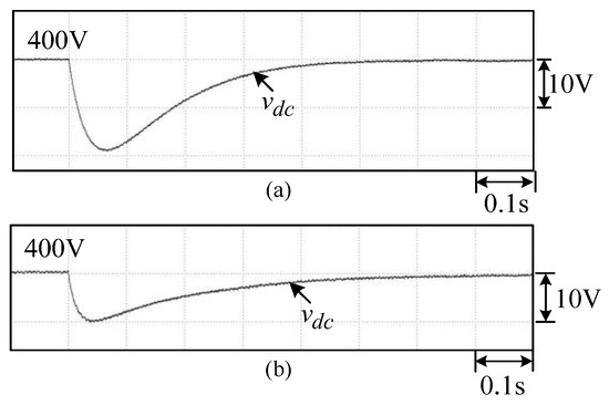
Figure 9.
Voltage responses of the developed 3LBC due to a step load change of : (a) the arbitrarily chosen controller for parameter estimation; (b) the quantitatively designed controller .
The simulation results (not shown here) have verified the correctness of the estimated dynamic model.
- Quantitative controller design:
Under the same operating point, the desired response is specified as ( and ) due to a step power change of With the known plant model parameters () listed in (14), one can list the following two nonlinear equations for the two independent variables and :
The parameters and are first solved from (15) and (16), then the PI controller parameters are obtained using (12) as follows:
The correctness of the quantitatively designed controller has been checked by simulation result (not shown here).
The measured due to a step load power change by the quantitatively designed controller is shown in Figure 9b, which verifies the correctness of the designed controller.
(b) Voltage robust error cancellation controller
In the VRECC shown in Figure 8a, the robust control weighting function is expressed as follows:
By adding the VRECC, the tracking error by PI control can only be reduced by a factor of as depicted in Figure 8b. Taking into account compromised considerations in control performance, magnified control effort, and system noise effects, the weighting factor is set.
3.2.5. MPPT Control Scheme
The perturb and observe (P&O) approach shown in Figure 10 is applied to conduct the MPPT control. As indicated in Figure 6, the modulation voltage is used as the control variable according to the changes in PV array output power and PV voltage . The MPPT algorithms can be divided into five cases: (i) Case 1: If the power is increased and the PV voltage is decreased, then ; (ii) Case 2: If is decreased and is decreased, then (iii) Case 3: If is increased and is increased, then (iv) Case 4: If is decreased and is increased, then . (v) Case 5: If is unchanged, then .
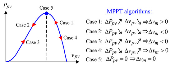
Figure 10.
Directionality judgment of for the MPPT algorithm.
3.2.6. Measured Results
(a) PV MPPT operations
The switch in Figure 6 is placed at position “M”, and the FC is disabled for testing the PV MPPT operation. A load resistor is connected to the DC microgrid DC-bus. Let the irradiance be changed from to in four steps. The measured results are shown in Figure 11. The successful MPPT operations with the tracked powers and voltages being close to the emulated P-V curves depicted in Figure 3 can be observed.
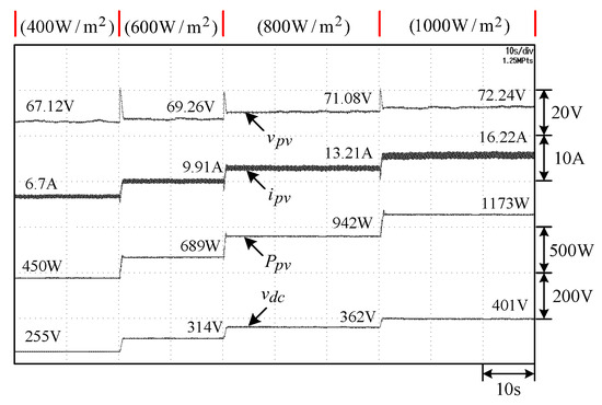
Figure 11.
Measured results of the PV under MPPT operation.
(b) Robust voltage regulation control
The switch in Figure 6 is placed at position “M”, and the FC is actuated. First, the PV is operated in MPPT mode under the irradiance of with . The DC bus is maintained at through FC support. Let the step load resistance change be applied . The measured results by PI control without and with robust control are shown in Figure 12. The results indicate that good voltage regulation responses are obtained, and a better response is obtained by adding robust control.
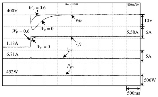
Figure 12.
Measured results due to a step load resistance change with and without robust control.
(c) PV MPPT operation with fuel cell energy support
The switch in Figure 6 is at position “M” for PV MPPT operation, and and are set. Figure 13 shows the measured results due to a step irradiance change of . From the results, it is found that the PV can always be operated at the maximum power point and the DC bus can be stably maintained at 400 V by the FC energy support.
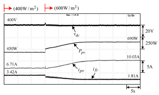
Figure 13.
Measured results of the MPPT operation with fuel cell support.
4. Grid-Connected Inverter
As indicated in Figure 2, the microgrid is connected to the utility grid via the 3P3W NPC inverter. The possible operation modes include microgrid-to-grid (M2G), grid-to-microgrid (G2M), and microgrid-to-home (M2H). As the PV/FC main sources and the BESS stored energy are deficient, the microgrid can support energy from the utility grid. The major system parameters are summarized below.
4.1. Power Circuit
- Output AC line rms voltage:
- Switching frequency: .
- Power devices: The IGBT module SK30MLI066 (600 V, 30 A) by Semikron Corp., Nuremberg, Germany.
- Output filter: (i) capacitors: ; (ii) inductors: measured inductances at 60 Hz are and
- Current and voltage sensing factors: . .
4.2. Control Scheme
The control scheme of the developed 3P3W inverter is shown in Figure 14. It mainly consists of phase-locked-loop (PLL) mechanism, droop control scheme, voltage-loop, and current-loop with RC-CCPWM scheme. The inverter is synchronously connected to the three-phase AC mains via the PLL mechanism. The designed controllers are listed below:
- PLL mechanism:
- PI current feedback controller:
- PI voltage controller in M2H mode:
- Droop control scheme in M2G/G2M operations: As indicated in Figure 14, the q-axis current command based on droop control varies from −8 A to 8 A within .
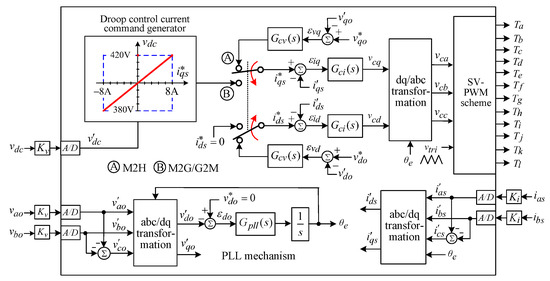
Figure 14.
Control scheme of the developed 3P3W NPC inverter.
5. Energy Storage System
The equipped hybrid energy storage system shown in Figure 1 consists of a PMSM-driven flywheel and a battery bank, they are respectively connected to the system DC bus via a 3L bidirectional NPC inverter and a boost-buck DC-DC converter. The development of the two storage systems and their coordinated control are introduced below.
5.1. PMSM-Driven Flywheel System
5.1.1. Power Circuit
(a) Flywheel
The photo and dimensions of the manufactured PMSM-driven flywheel system are shown in Figure 15. The key components are: (i) Moment of inertia ; (ii) PMSM: It is rated as: 8-pole, 2000 rpm, 2 kW, 9.8 N·m. The key motor parameters are d-axis inductance q-axis inductance Hence, it belongs to SPMSM with the assumed average .
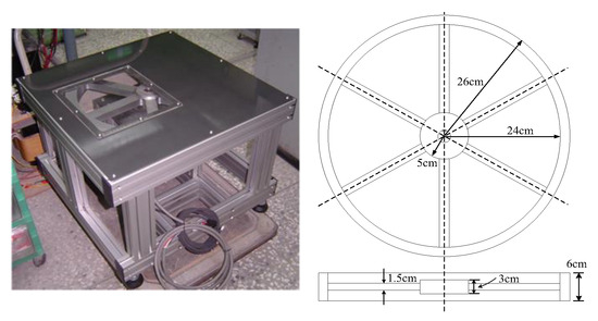
Figure 15.
Photo and dimensions of the manufactured PMSM-driven flywheel.
(b) Power devices
The IGBT module SK30MLI066 by Semikron Corp. is employed to form the developed 3L NPC inverter.
5.1.2. Control Schemes
Figure 16a shows the charging and discharging control schemes of the NPC inverter-fed PMSM-driven flywheel system. In charging mode, the flywheel is accelerated by using microgrid power through the NPC inverter operated in speed control mode. Conversely, the flywheel is discharged via the same inverter operated in SMR mode. The proposed current control scheme with the PMSM dynamic model under charging mode is shown in Figure 16b. In addition to the feedback controllers and the cross-coupling controllers and are designed to eliminate the inherent back-EMF cross coupling effects of PMSM. By using for SPMSM, through careful derivation, one can find that the ideal decoupling control can be achieved by setting the feedforward decoupling controllers as:
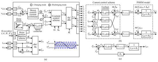
Figure 16.
The proposed control schemes of the developed PMSM-driven flywheel: (a) control scheme; (b) current control scheme; (c) decoupled q-axis current control scheme.
Accordingly, the decoupling feedback control can be made on the q- and d-axes. The q- and d-axis current feedback controllers are set to be identical Taking q-axis as a design example, the simplified black diagram is depicted in Figure 16c. The feedback controller is chosen to be of the PI type:
The PWM conversion constant and current sensing factor are set at 200 and .
The desired closed-loop current tracking response is designed by a first-order process with a time constant ( is set here):
The two-level carriers and are used in realizing the NPC inverter PWM scheme.
5.2. Battery Energy Storage System
5.2.1. Power Circuit
The designed circuit components are listed below:
- Lead-acid battery bank: , 14 Ah (1344 wh).
- Energy storage inductor:
- Filtering capacitors: .
- Switching frequency: .
- Current and voltage sensing factors: , .
- Power devices: The power MOSFET IXFN160N30T (,) by IXYS Corporation.
5.2.2. Control Scheme
The proposed control scheme of BESS with a 3L boost-buck converter is shown in Figure 17. The plant dynamic model derived using the state-averaging technique is as follows:
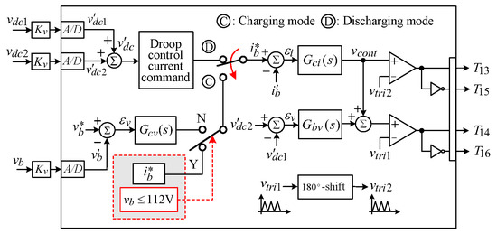
Figure 17.
The proposed control schemes of the developed BESS.
The current loop in discharging mode is designed as follows: at the operating point ), through computer simulation aided design, the PI current controller is designed to let the closed-loop current tracking transfer function have the crossover frequency with phase margin PM = .
5.3. Droop Control Scheme and Measured Results
5.3.1. Battery/Flywheel Droop Control Scheme
The droop control method is applied to handle the current sharing problems between the energy type BESS and the power type FW. The current commands of the BESS and the FW system are generated based on the algorithms depicted in Figure 18a,b. Taking BESS as an example, the current command yielded based on droop control varies from −5 A to 5 A within as indicated in Figure 18a.
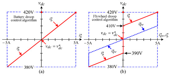
Figure 18.
Current command profiles based on the proposed droop control: (a) battery only; (b) flywheel and battery.
5.3.2. Measured Results
Figure 19 shows the measured results of the developed BESS/FW hybrid storage system operating characteristics. The boundary conditions are arranged as follows: the test loads are set to be the PV/FC source system, which is operated in MPPT mode, and the PV is set at .
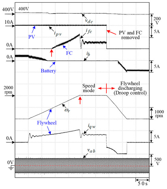
Figure 19.
Measured results of the developed BESS/FW hybrid storage system operating characteristics.
The preset operating scenario lies in: (1) PV supplies power to the load and charges to accelerate the flywheel. The surplus PV energy is used to charge the battery through the droop algorithm; (2) as the PV energy is insufficient, the battery is idled, and the FC discharges to support energy to supply the load and continuously accelerate the flywheel until the rated speed is reached; (3) the PV and FC are removed. The flywheel and battery power the load simultaneously, according to the droop algorithms. As the flywheel stored energy is exhausted, the battery remains to supply the uninterruptable power to the load. Normal operation can be determined from the results.
6. Integrated Operation of EVs
The total energy utilization may be further increased by considering the EV as movable energy storage to conduct its integrated operation on the developed airport microgrid. As shown in Figure 2, this task is fulfilled by a 3L CLLC resonant converter. The isolated DC voltage source is converted from the common DC-bus and used to perform EV off-board DC fast charging or on-board normal charging. In addition to this microgrid-to-vehicle (M2V) operation, the converse V2M operation is also applicable thanks to the bidirectional CLLC converter.
Figure 20a shows the related power circuit in this application. The control schemes of the EV battery system and CLLC converter are depicted in Figure 20b,c.
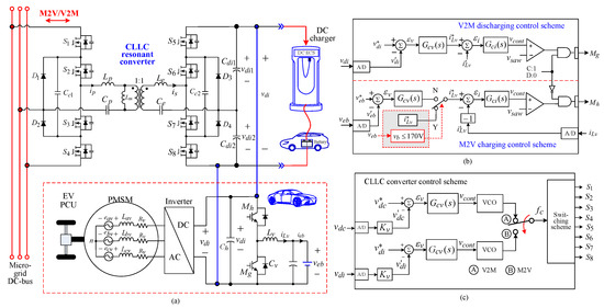
Figure 20.
System configuration of the developed airport microgrid under M2V operation: (a) power circuit; (b) control scheme of the EV battery front-end bidirectional DC/DC converter; (c) control scheme of the CLLC resonant converter.
6.1. EV Battery System
6.1.1. Power Circuit
The available EV power control unit is employed here for an experimental study. The system components of the battery bank and its bidirectional converter formed by () are summarized below:
- Battery bank: , 2 serially connected cells (UC Battery PS40138, 72 V–30 Ah).
- Bidirectional converter: It is constructed using the IGBT module CM100DY-12H () by Mitsubishi Company, Tokyo, Japan.
- Energy storage inductors: .
- Filter capacitor: .
- Switching frequency: .
6.1.2. Control Scheme
The arranged V2M/M2V control scheme is shown in Figure 20b. The designed controllers are listed as follows:
(a) Charging mode
The EV battery is initially charged in constant current mode with the command As the battery voltage reaches 170 V, the floating charging mode is applied. The PI voltage and current controllers are:
(b) Discharging mode
The outer voltage loop and inner current controlled PWM scheme control structure are arranged with the following controllers:
6.2. Three-Level CLLC Resonant Converter
LLC and CLLC resonant converters are commonly used to construct the EV on-board and off-board isolated chargers. If bidirectional operations are required, the CLLC converter must be adopted. In the established microgrid, the 3L CLLC converter depicted in Figure 2 and Figure 20a is developed to have a higher voltage rating and less voltage stress.
6.2.1. Power Circuit
In the resonant tank, only and are added externally. The inductances and are the transformer embedded magnetizing inductances and leakage inductances. All parameters are summarized as follows:
- , .
- Power switches: power MOSFET IPW65R019C7, manufactured by Infineon Company.
6.2.2. Control Scheme
(a) Frequency-modulated switching scheme
The frequency-modulated switching scheme using the controlled oscillator (VCO) is used. The varied frequency is set as:
where and is the control signal generated from the voltage controller.
(a) Voltage controller
The voltage sensing factor is set to be . The voltage feedback controllers of the bidirectional CLLC resonant converter in both directions shown in Figure 20c are chosen to be identical as follows:
6.2.3. Measured Results
The PV system is operated in MPPT mode, and the grid-connected inverter is activated under droop control. The measured results of the developed airport microgrid under microgrid-to-vehicle (M2V) are plotted in Figure 21a–c. The operating scenarios are:
- (i) PV irradiance is ; (ii) the microgrid without exhausting electricity and sends power to the grid (M2G mode, ).
- (i) EV battery is start to charge with ; (ii) the grid and PV in microgrid provide the charging power (G2M + M2V modes, ).
- (i) PV irradiance is changed from to ; (ii) the power supplied from the grid is reduced (G2M + M2V modes).
Normal operation and good performance of the developed microgrid in M2V mode can be verified from the results.
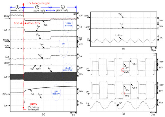
Figure 21.
Measured results of the airport microgrid under M2G, G2M, and M2V operations: (a) of grid-connected inverter, of PV, of CLLC converter, and of EV battery converter; (b) steady-state waveforms of EV battery converter; (c) steady-state waveforms , and of CLLC converter.
7. Integrated Operation of MEA
The landed aircraft can perform its integrated bidirectional operations on the airport microgrid. As indicated in Figure 2 and Figure 22 [40,41], the microgrid can be the alternative to the airport ground power unit (GPU) to power the MEA on-board facilities at the common DC-bus. The on-board common 400 Vdc bus is established by the airport microgrid using the PV and FC sources, the energy storage systems, and the utility grid. The MEA power architecture of 115 Vac/400 Hz AC-bus and 270 Vdc DC-bus is respectively established by the three-phase inverter and the DC-DC converter. In addition, a high-performance SRM drive with an asymmetrical bridge converter is powered by the 400 V common DC-bus.
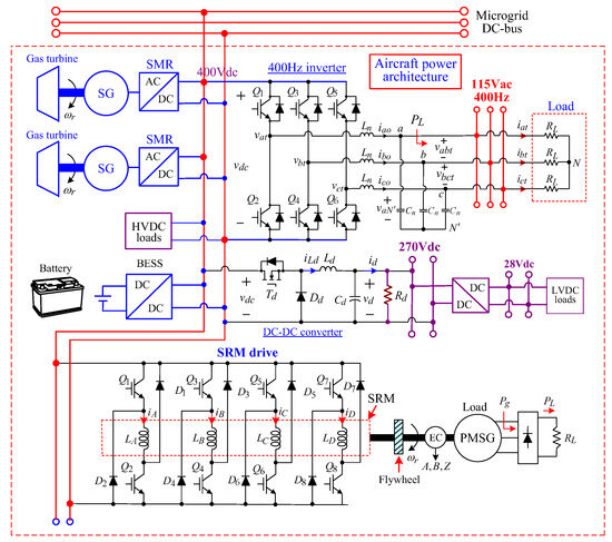
Figure 22.
System configuration of the developed airport microgrid under MEA interconnected M2A operation.
The power circuits and control schemes of these three power stages are introduced below.
7.1. 270 Vdc Converter
7.1.1. Power Circuit
- Input voltage: .
- Output voltage: .
- Switching frequency: .
- Energy storage inductor: .
- Output filtering capacitor: .
7.1.2. Control Scheme
The control scheme depicted in Figure 23a consists of a feedback controller and a command feedforward controller. The designed controllers are:
(a) PI voltage feedback controller
(b) Voltage command feedforward controller
The feedforward control signal is generated as:
where the voltage sensing-gain is and
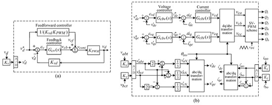
Figure 23.
Control schemes of the developed airport microgrid under MEA interconnected M2A GPU operation: (a) 270 Vdc converter; (b) 115 V/400 Hz high-frequency inverter.
7.2. 115 V/400 Hz High-Frequency Inverter
7.2.1. Power Circuit
The inverter system parameters are listed as follows:
- Three-phase HFAC bus voltage: Phase rms voltage .
- PWM switching frequency: .
- Current and voltage sensing factors: . .
- Output filters: and
7.2.2. Control Schemes
In the control scheme shown in Figure 23b, to provide the three-phase 115 V/400 Hz output AC voltage, the d-q voltage commands and the argument of sinewave are set. The designed controllers are listed below:
(a) PI current control scheme
(b) PI voltage control scheme
7.3. Switched-Reluctance Motor Drive
7.3.1. Power Circuit
The constituent components of the established SRM drive are summarized below:
- SRM: four-phase, 8/6 teeth, 400 V, 4 kW, 1500 rpm (TASC Drives Ltd., UK). The measured winding inductance profile and the arranged commutation mechanisms are shown in Figure 24.
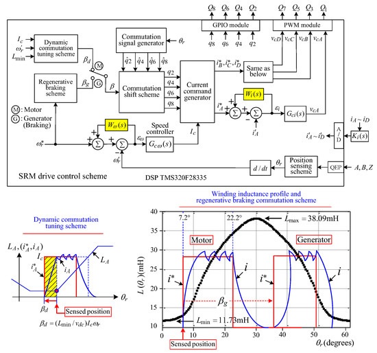 Figure 24. Control scheme of SRM drive.
 - PMSG: three-phase, 24 A, 4.5 kW, 2000 rpm.
- Dynamic load: rectifier with load resistance .
- Flywheel: .
- Asymmetrical bridge converter: It is constructed by two IGBT modules, CM100RL-12NF (Mitsubishi).
7.3.2. Control Scheme
Figure 24 shows the control scheme of the developed the SRM drive. It possesses an outer speed loop and an inner current loop [40]. In addition, the commutation scheme with proper shifts for motor and generator modes is also arranged. The designed controllers are described below.
(a) Current control scheme
The current feedback controller is chosen as the PI-type. In the design process [37], the upper limit of P-gain is first estimated using the large-signal stability criterion. Then, a suitable value of P-gain is chosen, and the I-gain is set to yield:
The robust current tracking error cancellation controller (RCECC) presented in [37] is modified to let the winding current tracking response be enhanced at higher speeds. The speed-dependent robust control weighting function is set as:
(b) Commutation shifting scheme
In motoring mode, the commutation advanced shift with an equivalent field-weakening effect is made to improve current tracking performance. The dynamic commutation tuning (DCT) scheme [37,41] as shown in Figure 24, is applied to conduct the commutation shift.
In conducting the regenerative braking, as shown in Figure 24, the commutation angle is shifted backward by to let the phase winding current be placed under the negative inductance slope region.
(c) Speed control scheme
The PI feedback speed controller is designed as:
In addition, the robust speed tracking error cancellation controller (RSECC) is added. The robust control weighting function is set.
7.4. Measured Results
7.4.1. MEA Major AC Bus and DC Bus
The following conditions are set for the experimental test: (i) the microgrid fuel cell is operated in constant voltage (400 V) mode, and the output maximum power is limited to 1.6 kW; (ii) the microgrid grid-connected inverter is operated under G2M mode with droop control (); (iii) the MEA inverter generates a three-phase 115 V/400 Hz output AC voltage under ; (iv) the MEA DC/DC buck converter generates , and its step load change is set to be . The measured results are plotted in Figure 25. From the results, one can observe the following facts: (i) In accordance with the load power changes, as the output power of the fuel cell is limited, insufficient power can be supplied from the utility grid via a grid-connected inverter; (ii) the 270 V DC-bus and the 115 V/400 Hz AC-bus are well regulated against the load changes.
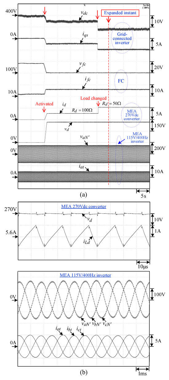
Figure 25.
Measured results of the landed MEA powered by the airport microgrid: (a) of grid-connected inverter, of fuel cell, of MEA 270 Vdc converter, of MEA 115 V/400 Hz inverter; (b) expanded steady-state waveforms of 270 Vdc converter and 400 Hz inverter.
7.4.2. SRM Drive
(a) Regenerative braking operation
The SRM drive is stably operated at , the PV system is operated in MPPT mode (), and the BESS is activated in constant voltage mode. Figure 26 shows the measured due to a ramp speed command change with a deceleration rate of 3500 rpm/s. The voltage rise in , the negative value of , and the increased battery voltage verify the successful regenerative braking operation.
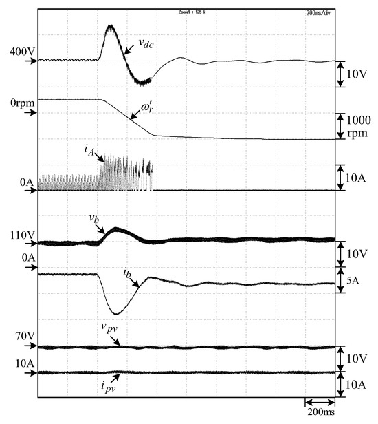
Figure 26.
Measured results of the SRM drive when operated in regenerative braking mode with a braking rate of 3500 rpm/s.
(b) SRM driving with an energy buffer
In order to evaluate the effects of the energy storage buffer on the SRM drive, the motor is operated with an with acceleration/deceleration rate of 500 rpms/s at In addition, the measured () of the developed SRM drive with energy storage buffer are plotted in Figure 27. The operating scenarios are:
- (i) The SRM drive does not work; (ii) PV irradiance is ; (iii) the microgrid does not exhaust electricity and sends power to the BESS ().
- (i) The SRM drive is operated from ; (ii) the BESS () and PV () in the microgrid provide the power to the SRM drive.
- (i) The SRM drive is operated from ; (ii) the BESS () and PV () in the microgrid continuously provide power to the SRM drive.
Reversible operation: The SRM drive is operated from 00. The scenario descriptions made above are repeated.
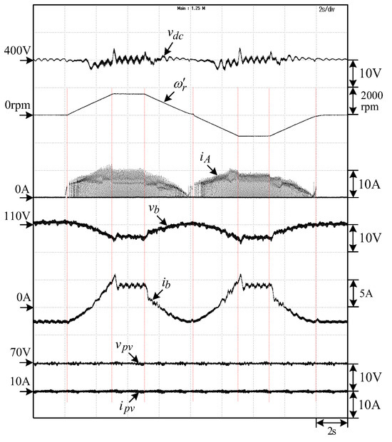
Figure 27.
Measured () of the SRM drive at () due to ramp speed command change of with both rising rate and falling rate of 500 rpm/s.
8. Conclusions
This paper presents an experimental airport bipolar DC microgrid powered by the main sources of PV and fuel cells. Due to the terrain limitations and safety reasons, renewable PV is chosen. Its unstable generation is supplemented by the zero-emission potential of the new energy source, FC. In addition, the bipolar DC-bus is adopted owing to its fault-tolerant capability. Each DC source is interfaced to the common DC bus via a 3L boost converter. Good current and voltage dynamic responses are obtained, respectively, by the developed OCC and robust control approaches. Satisfactory power sharing control is achieved by the PV MPPT with FC energy support approach.
A hybrid energy storage system consisting of an energy-type battery and a power-type flywheel with 3L bidirectional interface converters has been established. The proposed droop control is applied to yield good current-sharing characteristics between the two different types of energy storage devices. A dump load is equipped at the DC-link to avoid overvoltage.
For grid-connected operation and local load powering, a 3L NPC inverter is established. The grid-connected airport microgrid can further ensure its power supply reliability as the energy supply is deficient. The extensive measured results have verified that successfully coordinated operations between the microgrid input sources and the utility grid are achieved with satisfactory performance by the developed droop approach.
In addition, the innovative integrated operations of EV and MEA on the microgrid were conducted and evaluated experimentally. The movable energy storage application of EVs with M2V/V2M functions is achieved. The total energy utilization can be further enhanced. As to the landed aircraft, the developed microgrid possesses the GPU functions to power the MEA on-board facilities. The operating characteristics of the 270 V DC-bus, the 115 V/400 Hz AC-bus, and the SRM drive powered by the established airport microgrid have been demonstrated experimentally employing an available MEA power architecture. The incorporation of EV and MEA into the developed airport microgrid expresses its uniqueness, which is different from the conventional microgrid and can be a reference under development. Although the presented experimental airport microgrid is a scale-down prototype established in an academic research laboratory, the presented design procedures for power circuits and control schemes are unified. All the three-level converters adopted are suited for constructing large power microgrids. The improved coordinated controls between multiple sources, energy storage devices, the utility grid, EVs, and MEA are suggested to be further explored.
Author Contributions
Methodology, C.-M.L., C.-W.Y. and P.-H.J.; Validation, C.-W.Y. and P.-H.J.; Writing—original draft, C.-M.L.; Writing—review & editing, C.-M.L. All authors have read and agreed to the published version of the manuscript.
Funding
This research received no external funding.
Data Availability Statement
Data was contained within the article.
Conflicts of Interest
The authors declare no conflict of interest.
References
- Hatziargyriou, N.; Asano, H.; Iravani, R.; Marnay, C. Microgrids. IEEE Power Energy 2007, 5, 78–94. [Google Scholar] [CrossRef]
- Emadi, A.; Lee, Y.J.; Rajashekara, K. Power electronics and motor drives in electric, hybrid electric, and plug-in hybrid electric vehicles. IEEE Trans. Ind. Electron. 2008, 55, 2237–2245. [Google Scholar] [CrossRef]
- De Santiago, J.; Bernhoff, H.; Ekergård, B.; Eriksson, S.; Ferhatovic, S.; Waters, R.; Leijon, M. Electrical motor drivelines in commercial all-electric vehicles: A review. IEEE Trans. Veh. Technol. 2012, 61, 475–484. [Google Scholar] [CrossRef]
- Wheeler, P.; Bozhko, S. The more electric aircraft: Technology and challenges. IEEE Electrif. Mag. 2014, 2, 6–12. [Google Scholar] [CrossRef]
- Nasirian, V.; Moayedi, S.; Davoudi, A.; Lewis, F.L. Distributed cooperative control of DC microgrids. IEEE Trans. Power Electron. 2015, 30, 2288–2303. [Google Scholar] [CrossRef]
- Patterson, M.; Macia, N.F.; Kannan, A.M. Hybrid microgrid model based on solar photovoltaic battery fuel cell system for intermittent load applications. IEEE Trans. Energy Convers. 2015, 30, 359–366. [Google Scholar] [CrossRef]
- Dragičević, T.; Lu, X.; Vasquez, J.C.; Guerrero, J.M. DC microgrids—Part I: A review of control strategies and stabilization techniques. IEEE Trans. Power Electron. 2016, 31, 3528–3549. [Google Scholar]
- Xu, L.; Guerrero, J.M.; Lashab, A.; Wei, B.; Bazmohammadi, N.; Vasquez, J.C.; Abusorrah, A. A review of DC shipboard microgrids—Part I: Power architectures, energy storage, and power converters. IEEE Trans. Power Electron. 2022, 37, 5155–5172. [Google Scholar] [CrossRef]
- Merabet, A.; Ahmed, K.T.; Ibrahim, H.; Beguenane, R.; Ghias, A.M. Energy management and control system for laboratory scale microgrid based wind-PV-battery. IEEE Trans. Sustain. Energy 2017, 8, 145–154. [Google Scholar] [CrossRef]
- Kakigano, H.; Miura, Y.; Ise, T. Low-voltage bipolar-type DC microgrid for super high quality distribution. IEEE Trans. Power Electron. 2010, 25, 3066–3075. [Google Scholar] [CrossRef]
- Lin, S.; Huang, Y.; Liaw, C. Wind SRG-based bipolar DC microgrid with grid-connected and plug-in energy supporting functions. Energies 2023, 16, 2962. [Google Scholar] [CrossRef]
- Jin, Z.; Sulligoi, G.; Cuzner, R.; Meng, L.; Vasquez, J.C.; Guerrero, J.M. Next-generation shipboard DC power system: Introduction smart grid and dc microgrid technologies into maritime electrical networks. IEEE Electrif. Mag. 2016, 4, 45–57. [Google Scholar] [CrossRef]
- Hirose, K. DC microgrid for telecommunications service and related application. In Proceedings of the 2018 IPEC-Niigata 2018-ECCE Asia, Niigata, Japan, 20–24 May 2018; pp. 593–597. [Google Scholar]
- Matsumoto, A.; Fukui, A.; Takeda, T.; Yamasaki, M. Development of 400-Vdc output rectifier for 400-Vdc power distribution system in telecom sites and data centers. In Proceedings of the 2010 IEEE INTELEC, Orlando, FL, USA, 6–10 June 2010. [Google Scholar]
- Ganji, M. Airport microgrids: Transportation energy as a service. IEEE Electrif. Mag. 2020, 8, 121–124. [Google Scholar] [CrossRef]
- Kilimi, M.G.R.; Motjoadi, V.; Bokoro, P.N. Improvement of an off-grid electricity supply system: A case study in Corisco international airport. In Proceedings of the IEEE ICECCME, Mauritius, 7–8 October 2021; pp. 1–8. [Google Scholar]
- Zhao, H.; Xiang, Y.; Shen, Y.; Guo, Y.; Xue, P.; Sun, W.; Cai, H.; Gu, C.; Liu, J. Resilience assessment of hydrogen-integrated energy system for airport electrification. IEEE Trans. Ind. Appl. 2022, 58, 2812–2824. [Google Scholar] [CrossRef]
- Fagundes, T.A.; Fuzato, G.H.F.; Ferreira, P.G.B.; Biczkowski, M.; Machado, R.Q. Fuzzy controller for energy management and SoC equalization in DC microgrids powered by fuel cell and energy storage units. IEEE J. Emerg. Sel. Top. Ind. Electron. 2022, 3, 90–100. [Google Scholar] [CrossRef]
- Pires, V.F.; Cordeiro, A.; Foito, D.; Silva, J.F.A. Dual output and high voltage gain DC-DC converter for PV and fuel cell generators connected to DC bipolar microgrids. IEEE Access 2021, 9, 157124–157133. [Google Scholar] [CrossRef]
- Gao, Y.; Jausseme, C.; Huang, Z.; Yang, T. Hydrogen-powered aircraft: Hydrogen–electric hybrid propulsion for aviation. IEEE Electrif. Mag. 2022, 10, 17–26. [Google Scholar] [CrossRef]
- Vazquez, S.; Lukic, S.M.; Galvan, E.; Franquelo, L.G.; Carrasco, J.M. Energy storage systems for transport and grid applications. IEEE Trans. Ind. Electron. 2010, 57, 3881–3895. [Google Scholar] [CrossRef]
- Boicea, V.A. Energy storage technologies: The past and the present. Proc. IEEE 2014, 102, 1777–1794. [Google Scholar] [CrossRef]
- Hino, M.; Hara, D. Application of an energy storage system using lithium-ion batteries for more effective regenerative energy utilization. JR East Tech. Rev. 2014, 31, 23–26. [Google Scholar]
- Rocabert, J.; Capó-Misut, R.; Muñoz-Aguilar, R.S.; Candela, J.I.; Rodriguez, P. Control of energy storage system integrating electrochemical batteries and supercapacitors for grid-connected applications. IEEE Trans. Ind. Appl. 2019, 55, 1853–1862. [Google Scholar] [CrossRef]
- Kenny, B.H.; Kascak, P.E.; Jansen, R.; Dever, T.; Santiago, W. Control of a high-speed flywheel system for energy storage in space applications. IEEE Trans. Ind. Appl. 2005, 41, 1029–1038. [Google Scholar] [CrossRef]
- Abdeltawab, H.H.; Mohamed, Y.A.I. Robust energy management of a hybrid wind and flywheel energy storage system considering flywheel power losses minimization and grid-code constraints. IEEE Trans. Ind. Electron. 2016, 63, 4242–4254. [Google Scholar] [CrossRef]
- Murayama, M.; Kato, S.; Tsutsui, H.; Tsuji-Iio, S.; Shimada, R. Combination of flywheel energy storage system and boosting modular multilevel cascade converter. IEEE Trans. Appl. Supercond. 2018, 28, 1–4. [Google Scholar] [CrossRef]
- Wirasingha, S.G.; Emadi, A. Classification and review of control strategies for plug-in hybrid electric vehicles. IEEE Trans. Veh. Technol. 2011, 60, 111–122. [Google Scholar] [CrossRef]
- Williamson, S.S.; Rathore, A.K.; Musavi, F. Industrial electronics for electric transportation: Current state-of-the-art and future challenges. IEEE Trans. Ind. Electron. 2015, 62, 3021–3032. [Google Scholar] [CrossRef]
- Alagarsamy, T.; Moulik, B. A review on optimal design of hybrid electric vehicles and electric vehicles. In Proceedings of the IEEE I2CT, Mangalore, India, 27–28 October 2018; pp. 1–5. [Google Scholar]
- Kumar, G.V.; Zhuang, J.X.; Lu, M.Z.; Liaw, C.M. Development of an electric vehicle synchronous reluctance motor drive. IEEE Trans. Veh. Technol. 2020, 69, 5012–5024. [Google Scholar] [CrossRef]
- Kramer, W.; Chakraborty, S.; Kroposki, B.; Hoke, A.; Martin, G.; Markel, T. Grid Interconnection and Performance Testing Procedures for Vehicle-to-Grid (V2G) Power Electronics; Technical Report NREL/CP-5500-54505; National Renewable Energy Lab. (NREL): Golden, CO, USA, 2012. [Google Scholar]
- Ustun, T.S.; Ozansoy, C.R.; Zayegh, A. Implementing vehicle-to-grid (V2G) technology with IEC 61850-7-420. IEEE Trans. Smart Grid 2013, 4, 1180–1187. [Google Scholar] [CrossRef]
- Monteiro, V.; Pinto, J.G.; Afonso, J.L. Operation modes for the electric vehicle in smart grids and smart homes: Present and proposed modes. IEEE Trans. Veh. Technol. 2016, 65, 1007–1020. [Google Scholar] [CrossRef]
- Hsu, Y.C.; Kao, S.C.; Ho, C.Y.; Jhou, P.H.; Lu, M.Z.; Liaw, C.M. On an electric scooter with G2V/V2H/V2G and energy harvesting functions. IEEE Trans. Power Electron. 2018, 33, 6910–6925. [Google Scholar] [CrossRef]
- MMasrur, M.A.; Skowronska, A.G.; Hancock, J.; Kolhoff, S.W.; McGrew, D.Z.; Vandiver, J.C.; Gatherer, J. Military-based vehicle-to-grid and vehicle-to-vehicle microgrid-system architecture and implementation. IEEE Trans. Transp. Electrif. 2018, 4, 157–171. [Google Scholar] [CrossRef]
- Lu, M.Z.; Guo, Z.W.; Liaw, C.M. A battery/supercapacitor hybrid powered EV SRM drive and microgrid incorporated operations. IEEE Trans. Transp. Electrif. 2021, 7, 2848–2863. [Google Scholar] [CrossRef]
- Buticchi, G.; Bozhko, S.; Liserre, M.; Wheeler, P.; Al-Haddad, K. On-board microgrids for the more electric aircraft-technology review. IEEE Trans. Ind. Electron. 2019, 66, 5588–5599. [Google Scholar] [CrossRef]
- Yeoh, S.S.; Rashed, M.; Sanders, M.; Bozhko, S. Variable-voltage bus concept for aircraft electrical power system. IEEE Trans. Ind. Electron. 2019, 66, 5634–5643. [Google Scholar] [CrossRef]
- Yang, C.W.; Lu, M.Z.; Liaw, C.M. Development of an aircraft electric power architecture with integrated ground power unit. IEEE Trans. Aerosp. Electron. Syst. 2022, 58, 3446–3459. [Google Scholar] [CrossRef]
- Liaw, C.M.; Jhou, P.H.; Yang, C.W. Switched-reluctance motor drive for more electric aircraft with energy storage buffer. IEEE Trans. Aerosp. Electron. Syst. 2023, 59, 7423–7439. [Google Scholar] [CrossRef]
- Bhaskar, M.S.; Ramachandaramurthy, V.K.; Padmanaban, S.; Blaabjerg, F.; Ionel, D.M.; Mitolo, M.; Almakhles, D. Survey of DC-DC non-isolated topologies for unidirectional power flow in fuel cell vehicles. IEEE Access 2020, 8, 178130–178166. [Google Scholar] [CrossRef]
- Jung, J.; Kim, H.; Ryu, M.; Baek, J. Design methodology of bidirectional CLLC resonant converter for high-frequency isolation of DC distribution systems. IEEE Trans. Power Electron. 2013, 28, 1741–1755. [Google Scholar] [CrossRef]
- Zou, S.; Lu, J.; Mallik, A.; Khaligh, A. Bi-directional CLLC converter with synchronous rectification for plug-in electric vehicles. IEEE Trans. Ind. Appl. 2018, 54, 998–1005. [Google Scholar] [CrossRef]
- Marquardt, R. Modular multilevel converters: State of the art and future progress. IEEE Power Electron. Mag. 2018, 5, 24–31. [Google Scholar] [CrossRef]
- Ruan, X.; Li, B.; Chen, Q.; Tan, S.C.; Tse, C.K. Fundamental considerations of three-level DC-DC converters: Topologies, analyses, and control. IEEE Trans. Circuits Syst. I Regul. Pap. 2008, 55, 3733–3743. [Google Scholar] [CrossRef]
- Kan, Z.; Li, P.; Yuan, R.; Zhang, C. Interleaved three-level bi-directional DC-DC converter and power flow control. In Proceedings of the IEEE IGBSG, Yilan, Taiwan, 22–25 April 2018; pp. 1–4. [Google Scholar]
- Zhang, X.; Wang, B.; Manandhar, U.; Gooi, H.B.; Foo, G. A model predictive current controlled bidirectional three-level DC/DC converter for hybrid energy storage system in DC microgrids. IEEE Trans. Power Electron. 2019, 34, 4025–4030. [Google Scholar] [CrossRef]
- Schweizer, M.; Friedli, T.; Kolar, J.W. Comparative evaluation of advanced three-phase three-level inverter/converter topologies against two-level systems. IEEE Trans. Ind. Electron. 2013, 60, 5515–5527. [Google Scholar] [CrossRef]
- Barater, D.; Concari, C.; Buticchi, G.; Gurpinar, E.; De, D.; Castellazi, A. Performance evaluation of a three-level ANPC photo-voltaic grid-connected inverter with 650-V SiC devices and optimized PWM. IEEE Trans. Ind. Appl. 2016, 52, 2475–2485. [Google Scholar] [CrossRef]
- Lin, X.; Dong, D. SiC three-level neutral-point-clamped converter with clamping diode volume reduction using quasi-two-level operation. IEEE Trans. Power Electron. 2023, 38, 9839–9851. [Google Scholar] [CrossRef]
- Li, Y.; Zhang, H.; Liang, X.; Huang, B. Event-triggered-based distributed cooperative energy management for multienergy Systems. IEEE Trans. Ind. Inform. 2019, 15, 2008–2022. [Google Scholar] [CrossRef]
- Vašak, M.; Banjac, A.; Hure, N.; Novak, H.; Marušić, D.; Lešić, V. Modular hierarchical model predictive control for coordinated and holistic energy management of buildings. IEEE Trans. Energy Convers. 2021, 36, 2670–2682. [Google Scholar] [CrossRef]
- Yang, L.; Li, X.; Sun, M.; Sun, C. Hybrid policy-based reinforcement learning of adaptive energy management for the energy transmission-constrained island group. IEEE Trans. Ind. Inform. 2023, 19, 10751–10762. [Google Scholar] [CrossRef]
- Zhang, N.; Sun, Q.; Yang, L.; Li, Y. Event-triggered distributed hybrid control scheme for the integrated energy system. IEEE Trans. Ind. Inform. 2022, 18, 835–846. [Google Scholar] [CrossRef]
Disclaimer/Publisher’s Note: The statements, opinions and data contained in all publications are solely those of the individual author(s) and contributor(s) and not of MDPI and/or the editor(s). MDPI and/or the editor(s) disclaim responsibility for any injury to people or property resulting from any ideas, methods, instructions or products referred to in the content. |
© 2024 by the authors. Licensee MDPI, Basel, Switzerland. This article is an open access article distributed under the terms and conditions of the Creative Commons Attribution (CC BY) license (https://creativecommons.org/licenses/by/4.0/).