Abstract
The low-frequency disturbances transmitted by flexible cables are difficult to be attenuated for a novel disturbance-free payload spacecraft, which decreases the payload’s pointing accuracy and stability. In this research, a new spacecraft configuration with a high-precision inertial reference unit composed of capacitive sensors and a spherical test mass is proposed. The disturbance attenuation and pointing control system is subdivided into four interconnected control loops. The payload can be isolated from disturbances in the all-frequency band by the active vibration isolation control loop and the drag-free control loops, and its high-precision pointing requirement can be satisfied with the attitude pointing control loop and the attitude tracking control loop. An integrated control strategy is proposed, and the control system is decoupled into 12 single-input single-output control loops by pre-compensating, which lays the foundation for feedback design. Through the amplitude-frequency response analysis, the control bandwidth is designed according to the Proportional-Integral-Differentive control algorithm. The numerical simulations show that the disturbance attenuation performance is better than −20 dB in the all-frequency band, and the pointing accuracy and the pointing stability are better than 10−6 deg and 10−7 deg/s, respectively. The new spacecraft configuration and the disturbance attenuation and pointing control system provide a general technical solution for payloads with high-precision and high-stability requirements.
1. Introduction
A disturbance-free payload (DFP) spacecraft has been developed for certain space missions which have high-precision and high-stability requirements [1,2,3,4]. The DFP spacecraft is divided into two parts, namely the payload module (PM) and the support module (SM). The PM is isolated from disturbances on the PM via non-contact sensors and actuators. The DFP spacecraft was successfully demonstrated in previous experiments [5,6,7]. In the novel DFP spacecraft, several flexible cables connection between the PM and the SM create disturbances in the transmission path. The disturbances transmitted by flexible cables are mainly concentrated in the low-frequency region (e.g., 0.01 Hz to 1 Hz). The low-frequency disturbances are difficult to be attenuated, which decreases the pointing accuracy and stability of the PM [8].
At present, the main method for attenuating the disturbances caused by flexible cables is to establish a disturbance model and conduct feedforward compensation. The equating of the flexible cables connection between the two modules into a spring system is an accepted modeling method [9], and the equivalent stiffness matrix can be obtained through experiments [10]. However, due to the difficulty in measuring the rotational motion of the flexible cables, only the stiffness associated with linear motion can be obtained, resulting in the equivalent spring model not being able to reflect the rotational dynamics of the flexible cables. Another equivalent model of the flexible cables is established according to the momentum theorem and the theorem of the moment of momentum about the center of mass [11]. However, the equivalent model ignores the change of stiffness and damping led by the relative movement. Since the precise disturbance model of the flexible cables is difficult to establish due to the flexible characteristics such as the hysteretic curve and nonlinear stiffness, the feedforward compensation cannot effectively eliminate the low-frequency disturbances.
In this work, a novel technical approach is proposed to solve the problem of the low-frequency disturbances transmitted by flexible cables. The basic idea is to attenuate the low-frequency disturbances at the source rather than at the end of the transmission path. The low-frequency disturbances on the SM are hoped to be attenuated, so that the low-frequency disturbances transmitted by flexible cables will become smaller. Drag-free control technology is an effective means of attenuating the low-frequency disturbances of a spacecraft [12,13,14,15]. To eliminate the low-frequency disturbances, a free-flying test mass (TM) inside the spacecraft follows a purely gravitational orbit, and the spacecraft is controlled to track the free-flying TM by feedback the relative position of the TM with respect to its housing. Based on the DFP spacecraft and drag-free spacecraft design concept, an enhanced spacecraft architecture is designed to improve the payload’s pointing accuracy and stability performance. The TM is introduced into the enhanced DFP spacecraft, and drag-free control technology is used to attenuate the low-frequency disturbances of the SM.
The main contributions of this paper are the proposal of a new simple and effective control system configuration for the enhanced DFP spacecraft, as well as the design of an integrated control scheme with the abilities of full-band disturbance attenuation and high-precision pointing control. The rest of this paper is organized as follows. In Section 2, an overview of the hardware system is introduced to present the control system configuration of the enhanced DFP spacecraft. Section 3 is devoted to the design of the disturbance attenuation and pointing control system. The simulation results are discussed in Section 4, and the conclusions are offered in Section 5.
2. Control System Configuration
In the proposed spacecraft structure, a high-precision inertial reference unit is deployed in a DFP spacecraft with flexible cables, as shown in Figure 1. The inertial reference unit, which is rigidly attached to the body of the SM, consists of capacitive sensors and a spherical test mass. The capacitive sensors on the inner faces of the inertial reference unit sense the position of the spherical TM with respect to the SM. The spherical TM is able to fly without control, thus following a purely gravitational orbit. It is essential that the TM is spherical so that its attitude motion does not change the relative displacement of the SM with respect to the spherical TM. Referring to the control concept of the drag-free spacecraft, the low-frequency disturbances on the SM are attenuated by controlling the SM to track the free-flying TM, which is equivalent to the low-frequency disturbances transmitted to the PM through flexible cables being attenuated. At the same time, the high-frequency disturbances on the PM are attenuated by active vibration isolation control. Based on active vibration isolation control and drag-free control, the payload mounted on the PM can be isolated from disturbances in the all-frequency band. The payload’s pointing requirement can be achieved with the attitude pointing control of the PM and the attitude tracking control of the SM with respect to the PM.
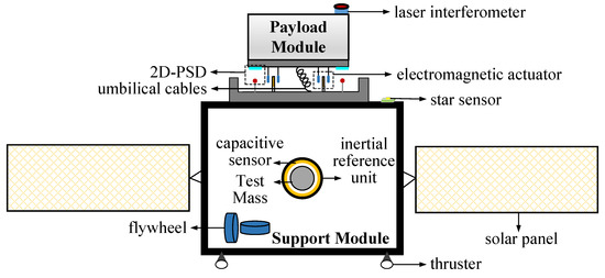
Figure 1.
Enhanced DFP spacecraft architecture. DFP, disturbance-free payload.
The control system of the enhanced DFP spacecraft includes 12 controlled DOF of the PM and the SM and six uncontrolled DOF of the TM. The control system of the enhanced DFP spacecraft can be subdivided into the four interconnected control loops presented in Table 1:

Table 1.
Control system of the enhanced DFP spacecraft.
1. An attitude pointing control (APC) loop is used to control the PM to track the desired attitude, which is determined by the payload’s pointing requirement, such as space scientific observation, deep space laser communication, and high-resolution earth observation. The star sensors mounted on the SM and the laser interferometer mounted on the PM are used to measure the payload’s pointing attitude. Three sets of electromagnetic actuators with two-dimensional force output are used to produce the required forces and torques for the PM. Each two-dimensional output electromagnetic actuator is composed of permanent magnets mounted on the PM and two sets of orthogonal coils mounted on the support module SM. Because these electromagnetic actuators only function well under the condition of adjacent coils and magnets, the motion of the PM with respect to the SM must be restricted in a limited space, such as ±10 mm in translation and ±35 mrad in rotation.
2. An attitude tracking control (ATC) loop is used to control the SM to track the attitude of the PM, which prevents a collision between the PM and the SM. Three sets of two-dimensional position-sensitive detectors (2D-PSDs) between the PM and the SM are used to measure the orientation of the PM with respect to the SM. Four flywheels are used to produce the required torques.
3. An active vibration isolation control (AVIC) loop is designed to attenuate high-frequency disturbances and prevent collisions. The 2D-PSDs sense the position of the PM with respect to the SM, and the electromagnetic actuators produce the required forces.
4. A drag-free control (DFC) loop is designed to attenuate low-frequency disturbances and prevent collisions. The capacitive sensors sense the position of the TM with respect to the SM, and the thrusters on the SM produce the required forces. The free motion of the TM with respect to the SM can be restricted within ±4 mm by the constrained spatial slot of the inertial reference unit.
3. Disturbance Attenuation and Pointing Control System Design
The system dynamics model of the enhanced DFP spacecraft can refer to the previously published paper [16]. A new disturbance attenuation and pointing control system is proposed, focusing on the integrated control strategy and coupling analysis, decoupling and feedback design, and amplitude-frequency response analysis and control bandwidth design.
3.1. Integrated Control Strategy and Coupling Analysis
The integrated application of the active vibration isolation control technology, the drag-free control technology and the spacecraft attitude control technology, the full-band disturbance attenuation and the high-precision pointing accuracy can be realized through the integrated control of the PM, SM and TM. The low-frequency disturbances are attenuated by the DFC loop and the high-frequency disturbances are attenuated by the AVIC loop. The DFC loop and the AVIC loop work together to achieve the payload’s full-frequency disturbance attenuation. Additionally, the PM is controlled to point to the target by utilizing the APC loop and the collision between the PM and the SM can be avoided by utilizing the ATC loop. The APC loop and the ATC loop work together to achieve the payload’s high-precision pointing requirement.
The control scheme of the enhanced DFP spacecraft is illustrated in Figure 2, in which the subscripts S, P, and T represent the SM, the PM, and the TM, respectively, and are replaced by the X below; , , , , , and are the forces generated by the Earth, the thrusters, the flexible cables, the electromagnetic actuators, the other internal disturbances, and the other external disturbances, respectively; , , , , , and are the torques generated by the Earth, the flywheels, the flexible cables, the electromagnetic actuators, the other internal disturbances, and the other external disturbances, respectively; and are the control forces and torques, respectively; is the attitude angle of the PM with respect to the geocentric inertial coordinate system; is the attitude angle of the SM with respect to the PM; is the relative displacement of the PM with respect to the SM; is the relative displacement of the SM with respect to the TM; and , , and are the desired values of the , , and , respectively.
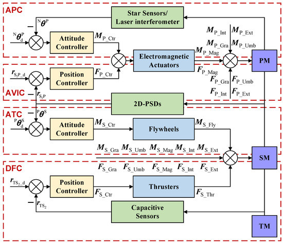
Figure 2.
Control scheme of the enhanced DFP spacecraft.
The four control loops of the enhanced DFP are coupled with each other, as shown in Figure 3, which is mainly reflected in:
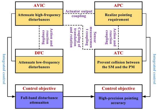
Figure 3.
Integrated control and coupling relationship of the enhanced DFP spacecraft.
(1) Sensor measurement coupling: The 2D-PSDs deployed between the PM and SM simultaneously measure the relative displacement and relative attitude of the PM with respect to the SM. The measurement of the relative displacement and the measurement of relative attitude are used for the AVIC and the ATC loop, respectively. Therefore, there is sensor measurement coupling between the AVIC and ATC loops.
(2) Actuator output coupling: The electromagnetic actuators deployed between the PM and the SM simultaneously output the control forces and control torques acting on the PM. The control forces and the control torques are used for the AVIC and the APC loop, respectively. Therefore, there is actuator output coupling between the AVIC and APC loops.
(3) Action and reaction coupling: The electromagnetic actuators output the control force acting on the PM while producing reaction interference for the SM, so there is action and reaction coupling between the AVIC and DFC loops. At the same time, the electromagnetic actuators output the control torques acting on the PM while producing reaction interference for the SM, so there is action and reaction coupling between the APC and ATC loops. Similarly, the flexible cables deployed between the PM and the SM also cause action and reaction coupling among the control loops.
(4) Coupling of translation and rotation: The reaction forces caused by the electromagnetic actuators and the flexible cables act on the SM, and torques are generated due to the deviation from the centroid of the SM. As a result, there is a coupling of the translation and rotation between the AVIC and ATC loops.
3.2. Decoupling and Feedback Design
After decomposing the acceleration terms into the control action of the actuators, disturbance and coupling stiffness, the dynamics model is expressed as
where is the acceleration caused by the thrusters; is the angular acceleration caused by the flywheels; and are the acceleration and the angular acceleration caused by the electromagnetic actuators, respectively; and are the acceleration and the angular acceleration caused by other disturbances, respectively; and are the mass ratio and the inertia ratio of the PM to the SM, respectively; and , , and are the coupling stiffnesses of the ATC loop, the AVIC loop and the DFC loop, respectively. With the assumption that the cross-coupling stiffnesses are all zeros, , , and are diagonal matrices.
To facilitate feedback design and control bandwidth design, the decoupling is carried out based on pre compensation. The pre compensation terms are derived mathematically based on the dynamic model, without considering the uncertainties of system parameters. If the , , , , and are estimated or observable, feedforward compensation is carried out to eliminate the influence of various disturbances. The output of the actuators can be designed as
where , , and are the feedback control part of the actuators.
Based on the integrated control strategy of the enhanced DFP spacecraft, the control system is decoupled by pre-compensating, and the output of the actuators can be further designed as
where , , and are the feedback terms for controlling coordinate errors.
According to Equations (1) and (3), the decoupled control model of the enhanced DFP spacecraft is expressed as
After the decoupling design, the APC loop, the ATC loop, the AVIC loop, and the DFC loop all achieve control input decoupling and are decomposed into a single-input single-output control system. The feedback control of the enhanced DFP spacecraft is designed as follows. The controller of the APC feeds back the attitude pointing coordinate , and the electromagnetic actuators output the control torques. The controller of the ATC feeds back the attitude tracking coordinate , and the flywheels output the control torques. The controller of the AVIC feeds back the active vibration isolation coordinate , and the electromagnetic actuators output the control forces. The controller of the DFC feeds back the drag-free coordinate , and the thrusters output the control forces. Therefore, the feedback terms for controlling the coordinate errors are designed as
According to Equations (3) and (5), the ideal outputs of the actuators are expressed as
3.3. Amplitude-Frequency Response Analysis and Control Bandwidth Design
The new disturbance attenuation and pointing control system of the enhanced DFP spacecraft is converted into 12 single-input single-output control loops through the decoupling and feedback design. The amplitude-frequency response is analyzed and the control bandwidth is designed based on the Proportional-Integral-Differentive (PID) control algorithm. The general form of the PID controller can be written as
In the above expression, , and are the PID controller parameters; and are the feedback coordinate and its first-order derivative, respectively; and are the desired value of the feedback coordinate and its first-order derivative, respectively; and is the control output.
According to Equations (4) and (7), the sensitivity function and the complementary sensitivity function of the closed-loop control loop can be expressed as
where and are the stiffness and damping of coupling disturbances, respectively, which are caused by factors including the flexible cables and relative measurement.
The sensitivity function and the complementary sensitivity function indicate the ability of the closed-loop feedback control system to attenuate indirect disturbances and direct disturbances, respectively. The indirect disturbances caused by flexible cables and the sensor noises are related to the feedback coordinates. The direct disturbances directly influence the controlled object, including external disturbances such as atmospheric resistance and solar radiation pressure, internal disturbances such as motor rotation and solar panel vibration, and actuator output noises. To analyze the amplitude-frequency response of the disturbance attenuation performance of the closed-loop feedback control system, the sensitivity function and the complementary sensitivity function are rewritten as a combination of several minimum phase typical elements. The sensitivity function and the complementary sensitivity function can be expressed as
where is the reciprocal of the time constant of the first-order inertia element; and are the undamped natural oscillation frequency and damping ratio of the second-order oscillation element, respectively; and and are the undamped natural oscillation frequency and damping ratio of the second-order differential element, respectively. The amplitude-frequency response of the minimum phase typical elements is clear. Figure 4 displays an example of the amplitude-frequency response of the closed-loop feedback control system. The indirect disturbances in the high-frequency band can be attenuated by the sensitivity function , while the direct disturbances in the low-frequency band can be attenuated by the complementary sensitivity function .
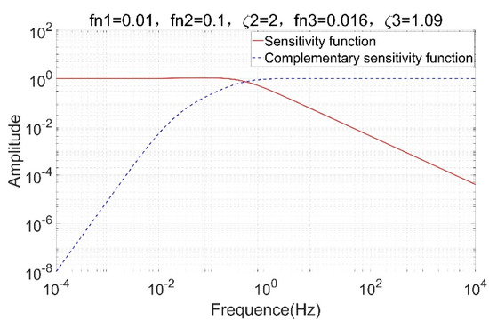
Figure 4.
Amplitude-frequency response of the closed-loop feedback control system.
The control bandwidth for each closed-loop control loop of the enhanced DFP spacecraft depends on the minimum phase typical element parameters. The APC loop attenuates the direct disturbances to improve the payload’s pointing accuracy, so the critical frequency of the complementary sensitivity function should be high, which means that the large control bandwidth is suitable for the APC loop. Furthermore, the ATC loop attenuates the direct disturbances to avoid a collision between the PM and the SM. Therefore, the critical frequency of the complementary sensitivity function should be high to generate large control bandwidth of the ATC loop. The AVIC loop is used to isolate the PM from the indirect disturbances in the high-frequency band, so the critical frequency of the sensitivity function should be low, which means that the small control bandwidth is suitable for the AVIC loop. The DFC loop is used to isolate the SM from the direct disturbances in the low-frequency band, so the critical frequency of the complementary sensitivity function should be high, which means that the large control bandwidth is suitable for the DFC loop.
The disturbance attenuation index of the disturbance attenuation and pointing control system exceeds −20 dB in the all-frequency band. In accordance with the design requirements of the amplitude-frequency response of each closed-loop control loop, the appropriate values of the minimum phase typical element parameters are determined and then the PID controller parameters are calculated. Comparing Equation (8) and Equation (9), the PID controller parameters can be expressed as
The design results are presented in Table 2.
Table 2.
Controller parameters of the enhanced DFP spacecraft.
4. Numerical Simulations
The simulation parameters of the enhanced DFP spacecraft can refer to the previously published paper [16]. This numerical simulation is based on the new disturbance attenuation and pointing control system, including the stability of integrated control, disturbance attenuation performance, and pointing accuracy and stability. The forces and torques caused by the gravitational attraction, solar radiation pressure, atmospheric drag, flexible cables, and structural vibrations are added to the dynamic integration, as shown in Figure 2. In the numerical simulations, the uncertainties of system parameters other than sensors and actuators are considered, and unknown disturbances are not included in the calculation of control forces and control torques.
4.1. Stability of Integrated Control
Figure 5 shows the centroid position of the PM with respect to the SM and shows the stability of the AVIC loop when the spatial constraint of ±10 mm is satisfied. Figure 6 shows the attitude angle of the PM with respect to the SM and shows the stability of the ATC loop when the spatial constraint of ±35 mrad is satisfied. Figure 7 shows the centroid position of the TM with respect to the SM and shows the stability of the DFC loop when the spatial constraint of ±4 mm is satisfied. Figure 5, Figure 6 and Figure 7 show the stability of the disturbance attenuation and pointing control system of the enhanced DFP spacecraft when the spatial constraints are satisfied.
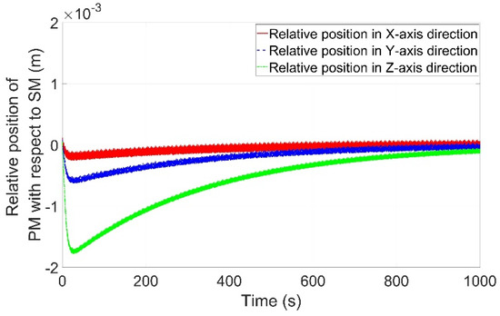
Figure 5.
Centroid position of the PM with respect to the SM. PM, payload module; SM, support module.
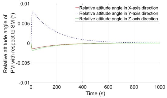
Figure 6.
Attitude angle of the PM with respect to the SM.
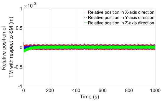
Figure 7.
Centroid position of the TM with respect to the SM. TM, test mass.
4.2. Disturbance Attenuation Performance
Figure 8 shows the disturbance accelerations in the frequency domain expressed in terms of the root mean square (RMS) per one-third octave band. The solid red line represents the disturbance acceleration of the SM without control which is equivalent to the disturbance acceleration of the SM in the novel DFP spacecraft. The dashed blue line represents the disturbance acceleration of the SM under control which is attenuated in the low-frequency band as expected. The dotted green line represents the disturbance acceleration of the PM under control which is clearly better than the disturbance acceleration of the SM without control in the all-frequency band. Figure 9 shows the disturbance attenuation performance. The disturbance attenuation performance of the AVIC loop is equivalent to the control performance of the novel DFP spacecraft, and the disturbances in the low-frequency band cannot be attenuated. With the DFC loop in the enhanced DFP spacecraft, the disturbance attenuation performance of the integrated control is better than −20 dB in the all-frequency band, which means that the disturbance at any frequency is attenuated by at least one order of magnitude. These simulation results can verify the effectiveness of the enhanced DFP spacecraft and the integrated control algorithm.
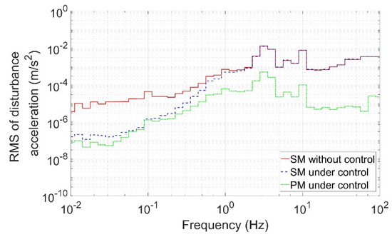
Figure 8.
Disturbance acceleration of the enhanced DFP spacecraft.
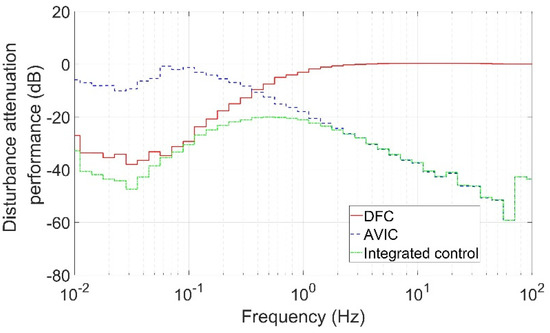
Figure 9.
Disturbance attenuation performance of the enhanced DFP spacecraft.
4.3. Pointing Accuracy and Stability
The control errors of the attitude angle of the PM and the attitude angular velocity of the PM are depicted in Figure 10 and Figure 11, respectively. As shown in these two figures, the pointing accuracy of the PM is better than an order of −6 and the pointing stability of the PM is better than an order of −7. These simulation results show that the high-level pointing accuracy and stability for the payload mounted on the PM is achieved by the disturbance attenuation and pointing control system of the enhanced DFP spacecraft.
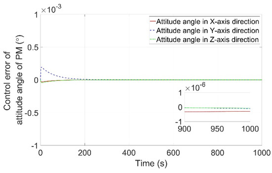
Figure 10.
Control error of the attitude angle of the PM.
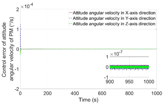
Figure 11.
Control error of the attitude angular velocity of the PM.
5. Conclusions
An enhanced DFP spacecraft is proposed to attenuate disturbances caused by flexible cables connection between the PM and the SM. An inertial reference unit composed of the TM and the capacitive sensors is introduced in the enhanced DFP spacecraft, and drag-free control technology is applied to attenuate disturbances for the SM in the low-frequency band. The disturbance attenuation and pointing control system is composed of four interconnected control loops, namely the APC, ATC, AVIC, and DFC loops. Based on the integrated control strategy, decoupling and feedback design, and control bandwidth design, the payload mounted on the PM can be isolated from disturbances in the all-frequency band, and the high-precision pointing requirement can be achieved. The numerical simulations demonstrate that the disturbance attenuation performance in the all-frequency band exceeds −20 dB, and the pointing accuracy and stability of PM are an order of −6 and −7, respectively. The control performance of the enhanced DFP spacecraft is clearly improved by the disturbance attenuation and pointing control system. The enhanced DFP spacecraft and its disturbance attenuation and pointing control system not only play a critical part in providing an extremely quiet on-board environment, but contribute to maintaining very high pointing accuracy, which will be useful for future work of most advanced space missions with related requirements.
Author Contributions
Conceptualization, T.J., G.K. and J.C.; Formal analysis, X.Z. and Z.Z.; Investigation, L.L. and F.L.; Methodology, T.J.; Software, T.J.; Validation, T.J., S.J. and J.Y.; Writing—original draft, T.J.; Writing—review and editing, T.J., G.K. and J.C. All authors have read and agreed to the published version of the manuscript.
Funding
This research received no external funding.
Institutional Review Board Statement
Not applicable.
Informed Consent Statement
Not applicable.
Data Availability Statement
The data presented in this study are available on request from the corresponding author. The data are not publicly available because the disturbance attenuation performance is the ratio of the disturbance accelerations before control to the disturbance accelerations after control, which is basically independent of simulation conditions.
Conflicts of Interest
The authors declare no conflict of interest.
References
- Pedreiro, N. Spacecraft architecture for disturbance-free payload. J. Guid. Control Dyn. 2003, 26, 794–804. [Google Scholar] [CrossRef]
- Dewell, L.D.; Tajdaran, K.; Bell, R.M.; Liu, K.; Bolcar, M.R.; Sacks, L.W.; Crooke, J.A.; Blaurock, C. Dynamic stability with the disturbance-free payload architecture as applied to the Large UV/Optical/Infrared (LUVOIR) mission. In Proceedings of the 2017 SPIE, San Diego, CA, USA, 6–10 August 2017; p. 103980B. [Google Scholar] [CrossRef]
- Bian, Z.Q.; Cai, C.S.; Lv, W.; Shen, Y.L. High Accuracy and High Stability Control Technology of Remote Sensing Satellite. Aerosp. Shanghai 2014, 31, 24–38. [Google Scholar] [CrossRef]
- Bronowicki, A.J. Vibration Isolator for Large Space Telescopes. J. Spacecr. Rocket. 2006, 43, 45–53. [Google Scholar] [CrossRef]
- Kong, Y.; Huang, H. Performance enhancement of disturbance-free payload with a novel design of architecture and control. Acta Astronaut. 2019, 159, 238–249. [Google Scholar] [CrossRef]
- Wu, C.; Kong, X.; Liu, Y.; Chen, Z. Coupling characteristics analysis for the disturbance free payload spacecraft. Acta Astronaut. 2017, 138, 407–416. [Google Scholar] [CrossRef]
- Kong, X.; Wu, C.; Li, H.; Yang, Z. Effect of back electromotive force on accurate pointing of disturbance-free-payload spacecraft. J. Natl. Univ. Def. Technol. 2019, 41, 75–81. [Google Scholar] [CrossRef]
- Zhou, J.; Liu, L.; Wang, Z.; Lil, J.; Deng, Y. On Pointing Accuracy and Pointing Stability of Disturbance-Free Payload Using Umbilical Connection. In Proceedings of the 37th Chinese Control Conference, Wuhan, China, 25–27 July 2018. [Google Scholar]
- Yang, H.; Liu, L.; Yun, H.; Li, X. Modeling and collision avoidance control for the Disturbance-Free Payload spacecraft. Acta Astronaut. 2019, 164, 415–424. [Google Scholar] [CrossRef]
- Fan, T.; Ren, W.; Li, Z. A Stiffness Testing System for the Umbilical of the Active Vibration Isolation System. Mech. Sci. Techn. Aerosp. Eng. 2016, 35, 1144–1148. [Google Scholar] [CrossRef]
- Wu, Q.; Liu, B.; Cui, N.; Yue, H.; Liu, R. Dynamic analysis of umbilical cables for maglev vibration isolation systems. AIAA J. 2019, 57, 1752–1762. [Google Scholar] [CrossRef]
- Lange, B. The drag-free satellite. AIAA J. 2011, 2, 1590–1606. [Google Scholar] [CrossRef]
- Tao, J.; Zhang, T. Relative position and attitude control for drag-free satellite with prescribed performance and actuator saturation. Trans. Nanjing Univ. Aeronaut. Astronaut. 2019, 36, 617–627. [Google Scholar] [CrossRef]
- Lian, X.; Zhang, J.; Wang, J.; Wang, P.; Lu, Z. State and disturbance estimation for test masses of drag-free satellites based on self-recurrent wavelet neural network. Adv. Space Res. 2020, 67, 3654–3666. [Google Scholar] [CrossRef]
- Rodrigues, M.; Robert, A.; Touboul, P.; Metris, G.; Prieur, P.; Cipolla, V.; Boulanger, D.; Chhun, R.; Christophe, B.; Guidotti, P.Y. Microscope satellite and its drag-free and attitude control system. Class. Quantum Grav. 2022, 39, 204003. [Google Scholar] [CrossRef]
- Jin, T.; Kang, G.; Cai, J.; Jia, S.; Yang, J.; Zhang, X.; Zhang, Z.; Li, L.; Liu, F. Integrated Control Scheme for an Improved Disturbance-Free Payload Spacecraft. Aerospace 2022, 9, 571. [Google Scholar] [CrossRef]
Disclaimer/Publisher’s Note: The statements, opinions and data contained in all publications are solely those of the individual author(s) and contributor(s) and not of MDPI and/or the editor(s). MDPI and/or the editor(s) disclaim responsibility for any injury to people or property resulting from any ideas, methods, instructions or products referred to in the content. |
© 2023 by the authors. Licensee MDPI, Basel, Switzerland. This article is an open access article distributed under the terms and conditions of the Creative Commons Attribution (CC BY) license (https://creativecommons.org/licenses/by/4.0/).