1. Introduction
A control valve is set in front of a fuel nozzle to control the speed and the starting and stopping processes of a gas turbine. Fuel valves operate for a long time in a high-temperature and high-pressure environment or start in a cold state, rendering them prone to changes in valve sleeve clearance. An increase in clearance can lead to an insufficient supply of gas turbine fuel pressure, and a decrease in clearance can render the valve prone to friction and sticking [
1]. Its structural accuracy can directly affect the parameters of the fuel outlet and the working stability [
2].
At present, the accuracy of fluid–solid coupling simulation is not sufficient. It is traditionally believed that fuel control valves deform due to the existence of regional eddy currents and fluid impacts. The stress response under gas pressure is used as the design basis for precision valve design. However, when valves need to be reused for a long time and at high intensity, such a basis is no longer sufficient. As a hot end component, spool deformation will be caused by stress circulation on the inner surface when used many times, and temperature will have a significant impact on the inner surface. This cannot be ignored [
3].
Qu [
4] carried out a fluid–solid coupling simulation analysis of a valve core, and then the structure of the valve core was improved, and its parameters were optimized based on the bird colony algorithm. An excellent structure and excellent parameters of the combined buffer groove were obtained, so that the pressure buffer of the regulating valve at the key position of the valve port achieved the best effect, and an effective solution was provided to solve the sticking of the valve core of the regulating valve. H [
5] analyzed the cavitation characteristics of a control valve based on switching conditions and discussed the mechanism of the working conditions and structural parameters with respect to the cavitation characteristics, which is important for anti-cavitation designs in control valves. Xie [
6] clarified the influence of coupling between the structure and the fluid system at the control valve; a coupling mechanism was presented, and numerical investigations were carried out. Under the same operating conditions, in which the pressure oscillation amplitude was greater when considering the coupling, the low-order natural frequencies of the plug assembly of the valve clearly decreased when considering the fluid–solid coupling action. S.K.R. et al. [
7] used computational fluid dynamics (CFDs) to design a combustion chamber for RCCI engines. The need for further improvements in the CFD models for RCCI engines was highlighted.
Amirante [
8] analyzed the flow field distribution of a proportional valve using Fluent software. The consistency relationship between the stress on the valve core and valve flow was highlighted. Lisowski [
9] analyzed a reversing valve’s flow field. A large floating flow can increase the flow power of the flow channel. The stress analysis results of valve cores have been mentioned in many studies. Other dangerous position stress analyses of the valve body are still lacking. Boye T et al. [
10] presented the design and modeling of transient flows in a crude oil pipeline system using a computer-based method.
In summary, valve components are prone to structural deformation in the fluid–solid coupling process, which can affect the accuracy of the outlet flow and even cause scrap failure.
Therefore, in fuel control valve design, it is necessary to comprehensively consider the coupling effect between the internal flow field, temperature field, and structure field, carry out research on the coupling characteristics of the thermal fluid–solid multiphysics field, clarify the stress distribution and structural deformation law of the fuel valve when considering multiple working conditions, and stably control the accuracy of the outlet gas flow.
In this study, compared with the results of traditional fluid–solid coupling studies, based on Fluent dynamic mesh technology, the fuel control valve of a gas turbine was numerically simulated with thermal fluid–solid coupling analysis. The deformation law of the valve components under flow and temperature fields was studied, and the influence amplitude of the thermal load and valve pressure on the valve flow accuracy under multiple opening conditions was obtained.
2. Theoretical Analysis and Modeling
2.1. Physical Mode
A fuel control valve is mainly composed of a body, core, cover, and stem (
Figure 1). There is a valve chamber in the middle of the valve body. One end is closed, and the other end is linked to a plug, which can change the channel area of the throat location, that is, the size of the valve opening (K). This is where the gas flows faster and the heat transfer of the fluid rises sharply, resulting in high strain. Therefore, theoretical and simulation research on the throat position is needed to avoid plug failure [
11]. After the gas enters the valve chamber, the fluid–solid coupling phenomenon occurs on the wall surface, which renders the fluid flow and heat transfer highly complicated. These forces all follow the laws of physics. Therefore, the intracavity fluid flow can be approximated as a kind of compressible fluid flow.
2.2. Governing Equation and Turbulence Model
Fluid flow follows the conservation laws of physics, including the basic conservation laws of mass, momentum, and energy. For a general compressible Newtonian fluid, the conservation law is described using the following governing equation:
Here, —volume force vector, —fluid density, —fluid velocity vector, and —shear force tensor.
The governing equation of the structure based on Newton’s second law is as follows:
Here, —solid density; —local acceleration vector in the solid domain; —Cauchy stress tensor; and —volume force tensor.
The RNG κ-ε turbulence model is based on recombination group theory under the effect of vortices on turbulence and the effect of the average strain rate on the dissipation rate. It can effectively handle flows with large streamline curvatures. Therefore, this model is adopted in this analysis.
The kinetic energy equation of turbulence pulsation is (
k equation):
is the generation term of turbulent kinetic energy K caused by the average velocity gradient; is the generation term of turbulent kinetic energy K caused by buoyancy; incompressible fluid: ; is a dissipative term; and is the compressibility correction term and the contribution of pulsation expansion in compressible turbulence.
The energy consumption equation of the turbulent kinetic energy is as follows (ε equation):
is the generation of ; is the buoyancy correction term; is the dissipative term; and and are the source terms of the k equation and ε equation, respectively.
2.3. Numerical Simulation Model
The simulation calculation is based on a 6% relative stroke of the valve stem. Each part is connected with bolts and fasteners. To reduce the coupling calculation, a physical simplification was carried out. After simplification, the model could be directly imported into the structure for subsequent coupling analysis. The imported model is shown in
Figure 2. The corresponding relation of the specific stroke of the valve stem is shown in
Table 1.
2.4. Boundary Conditions and Material Parameters
The inlet gas temperature is 200 °C, and the outlet pressure is the given nozzle gas pressure. The structure of the thermal fluid and solid can be analyzed by selecting the boundary conditions of convection heat transfer in the temperature field and the working conditions of the continuous wall. The relevant fuel and structural parameters are shown in
Table 2,
Table 3 and
Table 4.
2.5. Mesh Partitioning and Independence Verification
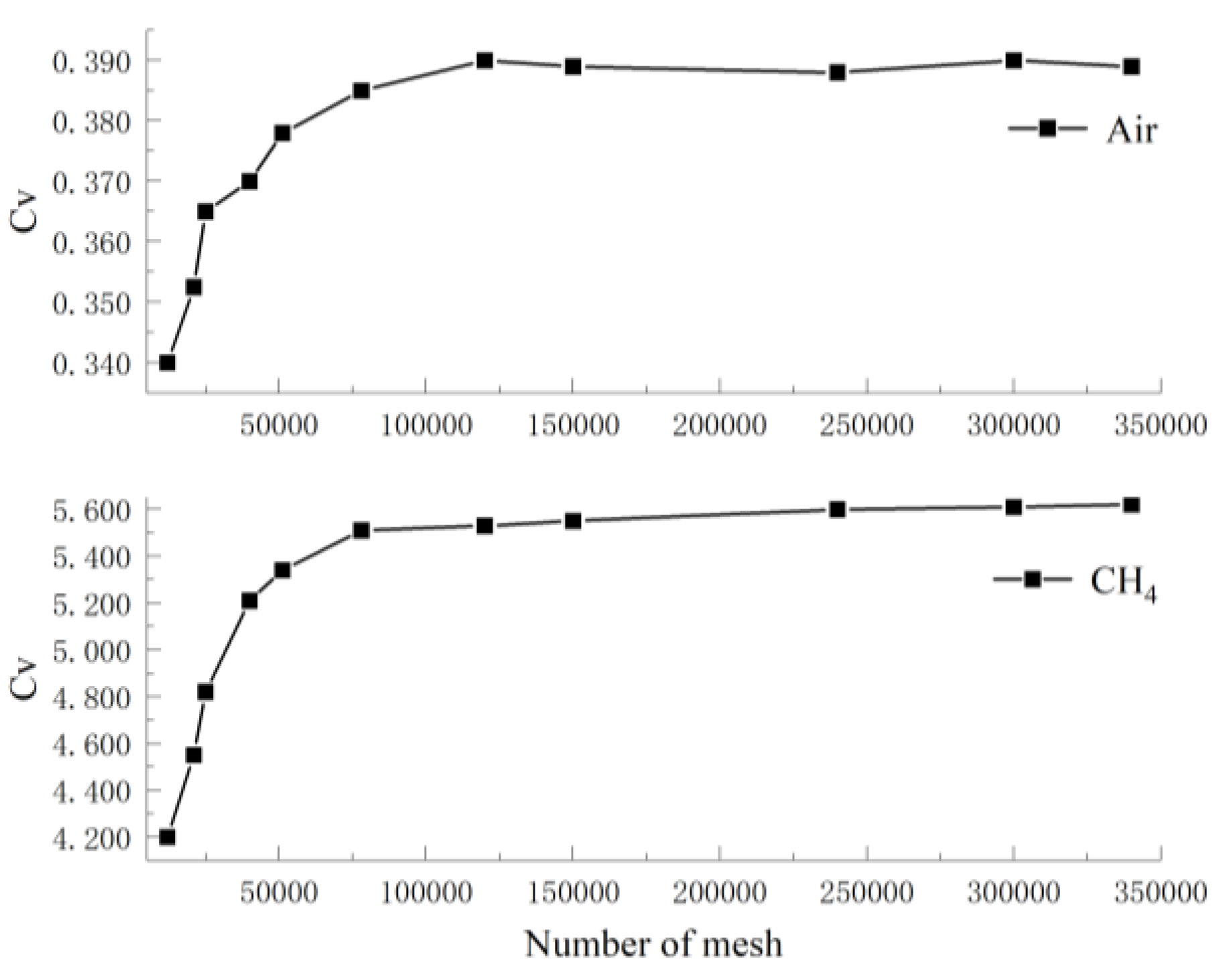
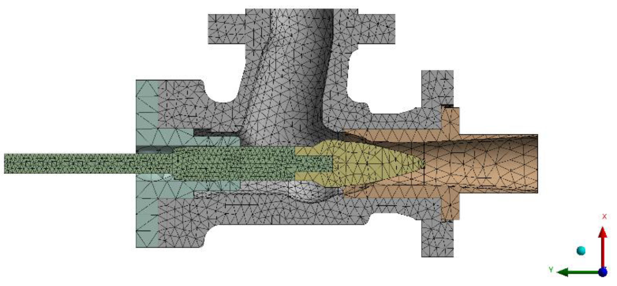
Only the spool and throat position structure encryption and regularization are considered for the solid domain mesh. Based on the fluid domain structure characteristics and heat transfer coupling properties of the fuel valve, four groups of tetrahedral mesh numbers were used to verify the mesh independence of the fluid mesh with a 2% valve opening. Methane was added for a comparative study, and the specific results are shown in
Figure 3.
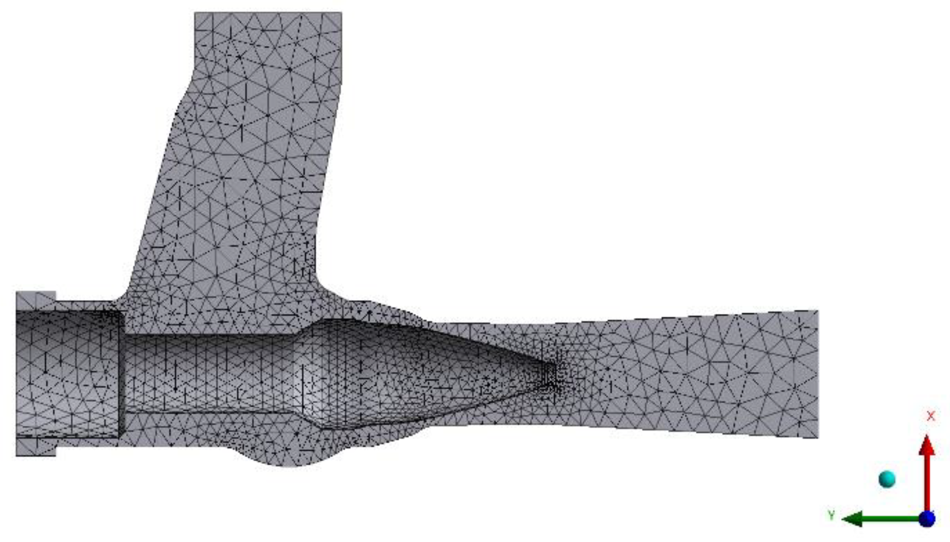
With a number of fluid grid cells greater than 80,000 units, the gas volume flow at the outlet section tends to be stable. The number of fluid grid units was finally selected as approximately 80,000 units, and the division results are shown in
Figure 4. The number of solid grid cells was selected as approximately 50,000 units, and the partitioning results are shown in
Figure 5, ensuring that y+ < 10.
2.6. Solver Setup
The SIMPLE algorithm of velocity and pressure coupling was selected for this simulation, and the discrete method of the second-order upwind scheme was adopted. To ensure convergence and stability in solving nonlinear equations, the residual governing equation was calculated to be less than 10−6 under transient conditions.
3. Coupled Flow and Dynamic Mesh Technology
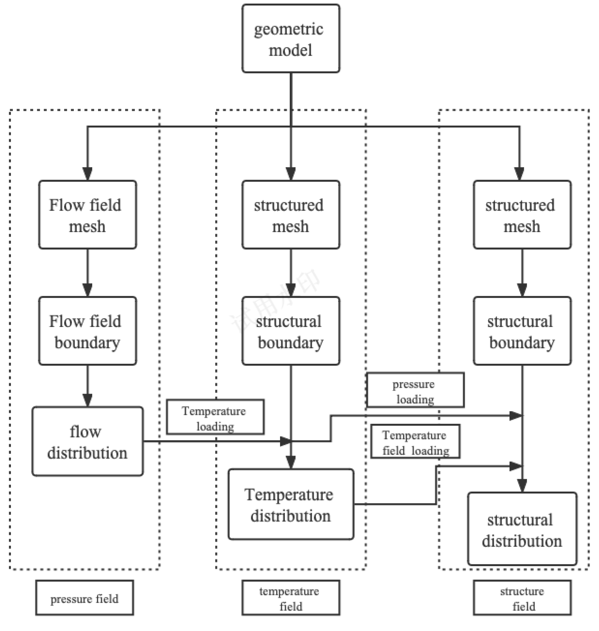
When solving the fluid domain, the solid domain is suppressed first. The contact interface between the structure and fluid is set as the system coupling region using CFD and Fluent. The data passing type is set to “All System Coupling Data Transfers”, rather than “Program Controlled”. The constraint is set to “displacement”. A bolt warning power is added to the system. The convergence residual is selected as the “RMS convergence target”. Five data transfer processes are involved in each time step: the fluid force to the solid, heat, and near-wall temperatures. The solids transfer increments in displacement and temperature to the fluid. The minimum number of iterations is 5, the maximum number of iterations is 10, and the end time is 15 s (
Figure 6).
For each data transfer in each calculation step, the Fluent software first calculates the force five times and then transmits the force to the structure. Then, the displacement and temperature calculated based on the structure are transferred to Fluent for grid updating, and then the force and displacement are recalculated. Through the changes in force, displacement, and temperature, the convergence of the data transfer in this calculation step is judged until the end of the program.
In the deformation and updating of the fluid mesh, dynamic mesh technology can prevent the negative mesh volume caused by mesh deformation on the basis of guaranteeing the convergence of the calculation. As tetrahedral mesh is easier to update with grid motion than hexahedral mesh, at present, dynamic mesh technology is mainly applied to the tetrahedral mesh [
12]. Using the Fluent software for the thermal fluid–solid coupling calculation of the gas fuel control valve to ensure the convergence of the calculation and less calculation time, the spring smoothing model is selected [
12,
13,
14].
4. Deformation Law and Stress Distribution of the Valve Body
Valve bodies in a state of thermal fluid–solid coupling will undergo thermal deformation. When deformation reaches a certain level, the fluid channel changes significantly, which can affect the export gas flow. Therefore, it is necessary to master the deformation law and consider the comprehensive factor analysis of the export gas flow. The simulation results of thermal fluid–solid coupling are shown in
Figure 7.
Deformation occurs at the beginning of the spool at approximately 2.5 s and then again in the middle of the valve cavity, which affects the bottom of the valve cavity and the throat. During this period, the spool position and shape variable increase further, and the deformation size shows a gradient change from the head to the tail, while the bonnet and seat, situated away from the flow path, remain small. Analyzing the gas stroke from the inlet to the outlet and observing the fluid velocity flow, it is clear that after the gas enters the valve chamber, the radial velocity of the gas at the entrance moves down along the wall. When the gas reaches the middle and lower positions of the valve chamber, the direction changes abruptly. The high-temperature and high-pressure gas constantly impacts the valve chamber, resulting in a concentration of stress on the wall and the transformation of gas kinetic energy into pressure potential energy, resulting in an uneven distribution of the pressure field. Therefore, the middle and lower parts of the valve chamber first produce thermal stress deformation. When the gas flow is stable, the pressure distribution in this section of the valve chamber tends to be uniform. Because of the thick outer structure, the impact of load factors is small. The average deformation is less than 0.02 mm. To avoid the change in the flow channel caused by deformation, the arc degree of the corner should be increased in the design so that the flow channel becomes smooth.
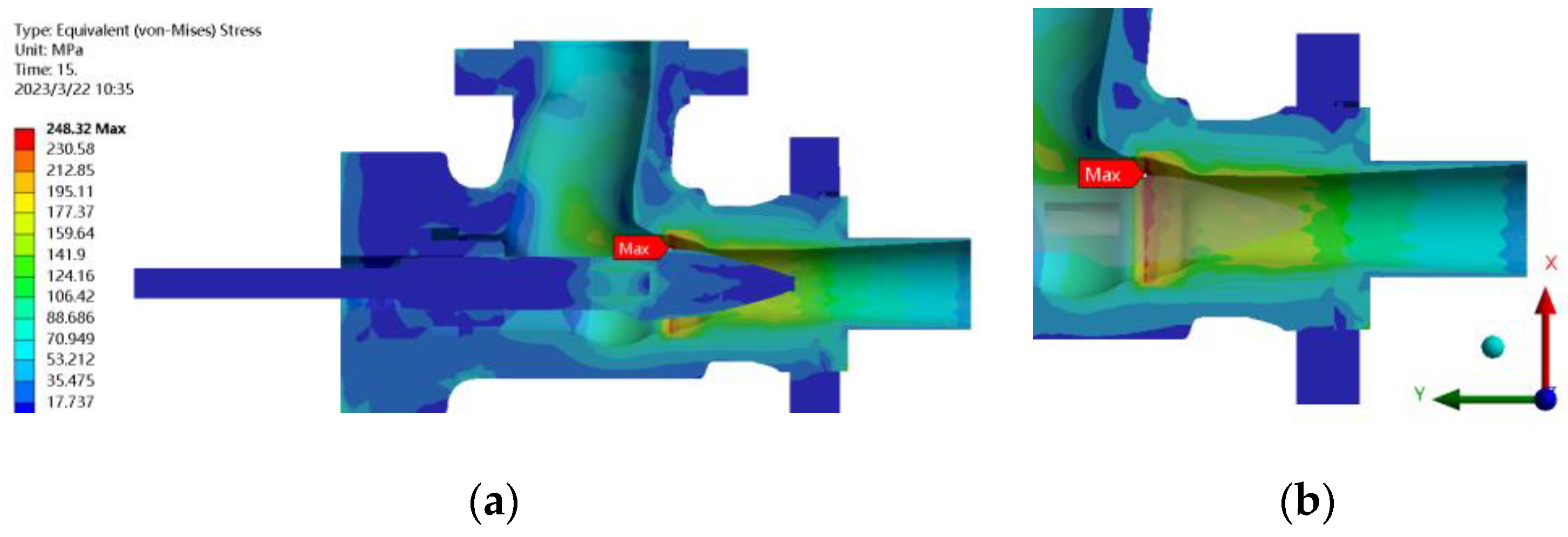
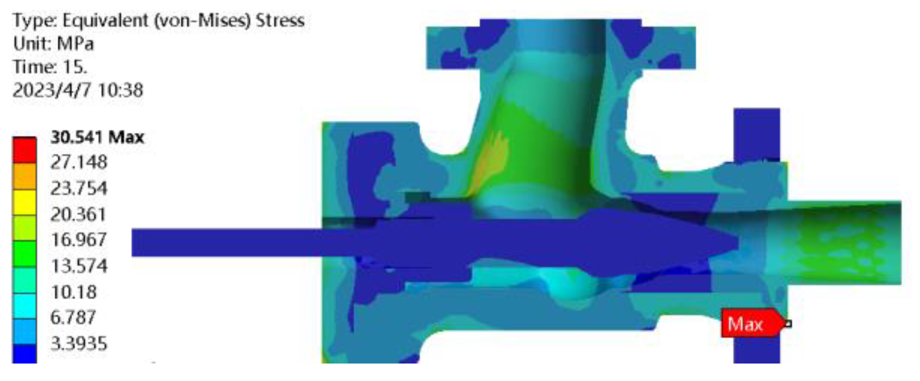
The deformation of the valve body is related to its stress distribution. The dangerous positions of the valve body under the two coupling states of fluid–solid coupling and thermal fluid–solid coupling are not the same. To study the stress concentration of the valve body under different working conditions, fluid–solid coupling and thermal fluid–solid coupling stress simulation analyses were carried out. The results are shown in
Figure 8 and
Figure 9.
In the traditional fluid–solid coupling condition, the maximum value of von Mises stress was 43.84 MPa at the lowest point of the valve seat. In the case of thermal fluid–solid coupling, the maximum von Mises stress appeared at the throat of the valve cavity, and the stress nephogram was distributed in a ring shape, with a maximum stress value of 248 MPa. At the same time, the stress gradually weakened along the fluid flow line, where the fluid flow line was the densest [
15]. As the fluid passed through the throat, the flow line dispersed, the gas force weakened, the temperature further decreased, and the stress nephogram showed an axial weakening trend.
5. Fluid Flow Line and Temperature Distribution
It can be seen from the velocity vector and pressure diagram of the flow field in
Figure 10 that there is high-velocity flow in this region. The highest velocity of the gas is 1665 m/s. The large velocity gradient causes the viscous force to work and generate heat, part of which causes the temperature to rise at the throat position through convective heat transfer. It can be seen in the flow diagram of the symmetrical surface that the flow lines are relatively dense in the front section of the throttle orifice. After the throttle port, the medium flow is separated from the outer wall. The stroke flow is separated, and the fluid velocity direction changes abruptly, forming a local small range of backflow at the flow passage near the valve head. The turbulent kinetic energy dissipation in the flow passage is mainly in the form of a vortex in a small area, which is in accordance with the law of energy conservation. After passing through the throat, the flow velocity gradually slows down.
Fluent software was used to analyze the flow channel separately. The average mass flow rate at the outlet section was 0.453 kg/s at 6% opening. After the coupling was completed, the data were postprocessed with CFD-Post. The average mass flow rate at the outlet section was 0.431 kg/s. Considering the calculation error, the deformation of the coupling spool affected the outlet flow accuracy by 4.8%. When the valve opening decreased to 4%, this proportion increased to 7.3%. This indicates that under the condition of a small opening, spool deformation will affect the outlet flow accuracy.
6. Effect of Valve Opening on Spool Deformation
The larger shape variable at the valve spool indicates that the cantilever structure is far from the fixed end of the valve stem and valve cover; it is affected by the change in the gas flow field and is more prone to deformation. Therefore, along the axial direction from the position of the valve stem to the position of the head of the outlet valve spool, the shape variable is distributed in a stepped shape. At the same time, in the pressure field, the local pressure loss of the throat is large, which leads to the conversion of fluid mechanical energy into heat energy. The ambient temperature near the outlet of the valve core is higher than that in other parts due to the gas friction and heat transfer temperature difference.
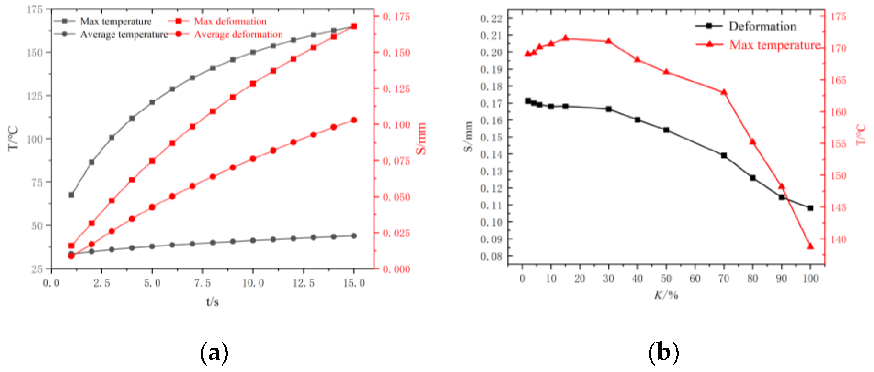
Based on the corresponding relationship between the relative stroke and upward distance of the valve stem shown in
Table 1, different relative strokes of the valve stem were selected to obtain statistics regarding the changes in the maximum shape variable and maximum temperature (see
Figure 11).
When K is below 40%, the maximum temperature of the valve core is not affected by the change in the opening degree and is stable at approximately 170 °C. In this case, part of the solid temperature rise is derived from the energy conversion caused by fluid friction and flow resistance. With increasing K, the throat area expands, and the loss coefficient of fluid kinetic energy is smaller than that of the valve with a small opening. The increase in solid temperature is mainly due to the heat transfer of the fluid temperature difference, which causes the maximum wall temperature of the valve with a large opening to be lower than it is in other cases. When K is greater than 70%, this effect is more significant, and the maximum temperature of the valve has a linear downward trend. When the valve opening increases to the 100% coupling condition point, the maximum temperature change range is −3.1%.
The change in the spool shape variable is the same(see
Figure 12). When
K is less than 40%, the spool deformation is less affected by the change in the opening, which is maintained near 0.17 mm. When
K is greater than 40%, the change in the maximum shape variable is accelerated. The maximum variation is −6.94%. As shown in
Figure 11, the profile is formed along the symmetry plane of the spool, and the y value corresponds to the relative position of the spool profile. The larger the y value is, the closer it is to the spool head. In the figure, when the y value is small, the opening
K has little influence on the deformation. When the y value increases, the closer the position is to the head, the greater the increase in deformation is. At the same time, the overall deformation fluctuates when y = 0. The reason for this is that on the left side of the 0 value, the maximum stress of the whole valve body is at the point where the spool and stem are connected. The 0-value right spool design structure thickens, and the deformation response is slow.
7. Influence of Thermal Load on Spool Deformation
The deformation of the valve core is closely related to the heat load applied by the fluid, which cannot be ignored when calculating the strength of the valve structure [
16,
17]. To quantitatively study the influence amplitude of the heat load, a traditional fluid–solid coupling simulation (F-S) was adopted for the model without heat transfer. Based on a comparison with thermal fluid–solid coupling (T-F-S), the results are shown in
Figure 13.
The variation trends of the two coupling methods are consistent, which indicates the accuracy of the coupling simulation results.
Table 5 shows that the thermal load has a strong influence on the valve structure’s deformation, and the thermal load factor plays a dominant role in the valve core’s deformation under each opening degree. When the valve opening is 2%, the proportion reaches 93%, while with the
K value increasing, the proportion of fluid–solid coupling reaches 24%. When the inlet gas temperature rises to the limit temperature of 210 °C, the proportion affected by thermal load reaches 94.3%. According to the research results of the pilot proportional directional valve [
18] and
Figure 13, the traditional fluid–solid coupling method cannot meet the high-precision requirements of valve simulation. Under the condition of a small valve opening, thermal load plays a decisive role in the deformation of the dangerous position of the valve spool. The inlet gas temperature should be strictly controlled to prevent the valve spool from sensitive deformation sticking failure due to high temperature rise.
8. Influence of Pressure Difference on Flow Accuracy
Under different opening conditions, due to the complexity of the valve working conditions, the pressure difference between the inlet and outlet gases is not stable. The results of the valve performance experiment show that when the pressure ratio ranges from 0.415 to 0.762, the valve flow, under the same opening conditions, is completely unrelated to the pressure behind the valve, according to which it is in a critical flow state and presents linear regulation characteristics [
19,
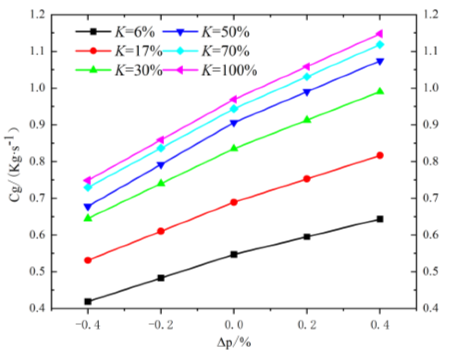
20]. Considering the constant pressure behind the valve, the influence of the change in pressure difference on the outlet gas flow rate was quantitatively studied. The pressure difference and stem displacement changed proportionally. The outlet flow rate data were obtained, as shown in
Figure 14.
When
K < 40%, the change in outlet flow caused by opening is 25.9%. The outlet flow change caused by the pressure difference is 17.6%. When
K > 40%, the outlet flow change caused by opening is 2.7%. The change in the outlet flow rate caused by the pressure difference is 18.4%. This result shows that the fuel valve has the “quick-opening characteristic” [
20]; that is, at a small
K value, the change in valve opening can cause the outlet gas flow rate to change quickly, and the response is sensitive to the realization of “quick-opening”. With a large
K value, the opening has little influence on the flow rate, and the stability of the gas pressure before the valve is the main factor affecting the flow rate at the outlet [
21]. With a large opening, the outlet gas flow increases by 8% under the limit working condition of a 3.05 MPa inlet pressure. Therefore, on the basis of ensuring a wide opening pressure ratio range from 0.415 to 0.762, it is necessary to strictly stabilize the gas pressure in front of the valve so as to avoid pressure fluctuation, which affects the accuracy of the outlet flow [
22].
9. Conclusions
Thermal fluid–solid interactions between a structure and a fluid system at the control valve must be taken into account for an analysis of the control valve’s characteristics. This paper used a spring smoothing model dynamic mesh to carry out a numerical simulation. This method is highly useful for gaining a better understanding of the detailed flow physics that occur in the control valve. Based on a comparison with the traditional fluid–solid coupling results, the influences of various factors on the valve outlet flow accuracy can be summarized as follows:
- (1)
The thermal deformation in the coupling system has an impact on the stability of the outlet flow rate. The influence of the flow accuracy at 6% valve opening and 4% valve opening are increased by 4.8% and 7.3%, respectively.
- (2)
When the valve opening is less than 40%, the maximum shape variable of the spool is less affected by the change in the opening. When the valve opening degree is greater than 40%, the change in the maximum shape variable is accelerated. The maximum variation is -6.94%. To ensure the valve outlet gas flow’s accuracy under the condition of a small opening, it is necessary to control the working time of the small opening. According to the valve “quick-opening characteristic”, after the end of the warm machine operation period, the gas must pass through the low opening smoothly and quickly.
- (3)
The influence of thermal load on spool deformation is more significant in the coupling state. The thermal load plays a decisive role in the deformation of the spool under the condition of a small opening. When the valve is working with a small opening degree, the inlet gas temperature should be strictly controlled, and the temperature fluctuation should not exceed 5% of the set temperature.
- (4)
When the valve opening degree is greater than 40%, the outlet flow rate change caused by the change in pressure difference is 18.4%, which is much larger than the flow change caused by the same opening degree. Under the condition of a large opening, when the pressure ratio is 0.415–0.762 within the critical flow range, the gas pressure in front of the control valve should be strictly uniform to ensure the stability of the gas flow at the control valve outlet.
Author Contributions
Conceptualization, H.P.; methodology, K.L.; software, H.P.; validation, W.L.; formal analysis, H.P.; investigation, R.W.; resources, K.L.; data curation, Z.L.; writing—original draft preparation, H.P.; writing—review and editing, W.L.; visualization, H.P. (Haoran Pan); supervision, W.L.; project administration, K.L. and L.X.; funding acquisition, L.X. All authors have read and agreed to the published version of the manuscript.
Funding
This research was funded by the Major Science and Technology Projects for Aeroengines and Gas Turbines (NO. J2019-V-0014-0109).
Data Availability Statement
Not applicable.
Conflicts of Interest
The authors declare no conflict of interest.
References
- Cheng, W.; Peng, H. Dependence of flow coefficient on the cone angle and relative opening of natural gas control ball valves. Trans. Inst. Meas. Control 2023, 45, 649–660. [Google Scholar] [CrossRef]
- Dai, Q.; Zhao, J.; Li, S.; Jia, W. Characterization of 2D Electrical Feedback Flow Control Valve. Machines 2023, 11, 220. [Google Scholar] [CrossRef]
- Hong, L.X.; Jian, K.; Ying, Y.L. Research on Temperature distribution in Radial Clearance of hydraulic slide Valve. Mach. Tools Hydraul. 2006, 11, 107–109. [Google Scholar]
- Guo, Q.; Li, J.; Peng, C.; Guo, Q. Structure improvement and parameter optimization of micro flow control valve. Sci. Rep. 2023, 13, 6850. [Google Scholar]
- Wang, H.; Zhu, Z.; Xu, H.; Li, J. Effects of throttling structures on cavitation flow and circumferential uniformity in a control valve. Eng. Fail. Anal. 2022, 134, 106025. [Google Scholar] [CrossRef]
- Xie, Y.; Yong, W.; Liu, Y.; Cao, F.; Pan, Y. Unsteady Analyses of a Control Valve due to Fluid-Structure Coupling. Math. Probl. Eng. 2013, 2013 Pt 11, 206–232. [Google Scholar] [CrossRef]
- Dwarshala, S.K.R.; Rajakumar, S.S.; Kummitha, O.R.; Venkatesan, E.P.; Veza, I.; Samuel, O.D. A Review on Recent Developments of RCCI Engines Operated with Alternative Fuels. Energies 2023, 16, 3192. [Google Scholar] [CrossRef]
- Amirante, R.; Moscatelli, P.G.; Catalano, L.A. Evaluation of the flow forces on a direct (single stage) proportional valve by means of a computational fluid dynamic analysis. Energy Convers. Manag. 2007, 48, 942–953. [Google Scholar] [CrossRef]
- Lisowski, E.; Czyżycki, W.; Rajda, J. Three dimensional CFD analysis and experimental test of flow force acting on the spool of solenoid operated directional control valve. Energy Convers. Manag. 2013, 70, 220–229. [Google Scholar] [CrossRef]
- Boye, T.; Samuel, O.D. Computer-based method of design and modeling of transient flow in crude oil pipeline system. J. Eng. Res. 2020, 8, 219–239. [Google Scholar] [CrossRef]
- Nian, Y.; Gao, L.; Li, R.; Wu, X.; Wang, E. A Hybrid Grid-Based Finite-Element Approach For 3D Steel Casing Forward Modeling. Adv. Theory Simul. 2021, 5, 2100398. [Google Scholar]
- Stein, K.; Tezduyar, T.; Benney, R. Mesh Moving Techniques for Fluid-Structure Interactions with Large Displacements. ASME. J. Appl. Mech. 2003, 70, 58–63. [Google Scholar] [CrossRef]
- Keith, S.; Tayfun, E.; Tezduyar, R.B. Automatic mesh update with the solid-extension mesh moving technique. Comput. Methods Appl. Mech. Eng. 2004, 193, 2019–2032. [Google Scholar]
- Yong, M.; Chuan, L.R.; Peng, Z. Fluid-structure coupling finite element analysis of slide valve multiway valve. Mach. Tools Hydraul. 2019, 47, 109–113. [Google Scholar]
- Hua, H.L.; Bei, G.; Jian, Z. Study on fluid-solid thermal coupling of multi-way valve spool. Hydraul. Pneum. 2020, 11, 87–92. [Google Scholar]
- Rad, C.R.; Hancu, O.; Maties, V.; Lapusan, C. Parameter Identification and Modeling of a Pneumatic Proportional Valve with Applicability in Control Design of Servo-Pneumatic Systems. Appl. Mech. Mater. 2014, 3518, 700–705. [Google Scholar] [CrossRef]
- Chen, F.Q.; Jin, Z.J. Throttling components effect on aerodynamic performance of superheated steam flow in multi-stage high pressure reducing valve. Energy 2021, 230, 120769. [Google Scholar] [CrossRef]
- Qing, S.C.; He, X.; Tong, Z.Z. Modeling and optimization of novel ball valve with high adjustable ratio. Int. J. Press. Vessel. Pip. 2021, 190, 104299. [Google Scholar]
- Yoon, W.; Yoon, H.; Ahn, J.; Ahn, K. Flow measurement and instrumentation flow control characteristics of throttling venturi valve with adjustable area. Flow Meas. Instrum. 2021, 81, 102034. [Google Scholar] [CrossRef]
- Topçu, E.E.; Yüksel, İ.; Kamış, Z. Development of electro-pneumatic fast switching valve and investigation of its characteristics. Mechatronics 2006, 16, 365–378. [Google Scholar] [CrossRef]
- Li, W.Q.; Zhao, L.; Yue, Y.; Wu, J.-Y.; Jin, Z.-J.; Qian, J.-Y. Thermo-mechanical stress analysis of feed-water valves in nuclear power plants. Nucl. Eng. Technol. 2022, 54, 849–859. [Google Scholar] [CrossRef]
- Sheng, G.C. Flow Field Simulation and Spool Motion Analysis of Pressure Regulating Valve Based on Dynamic Mesh. Ph.D. Thesis, Chongqing University, Chongqing, China, 2013. [Google Scholar]
Figure 1.
Physical model of the gas fuel control valve.
Figure 1.
Physical model of the gas fuel control valve.
Figure 2.
Model of the gas fuel control valve.
Figure 2.
Model of the gas fuel control valve.
Figure 3.
Fluid mesh independence verification results.
Figure 3.
Fluid mesh independence verification results.
Figure 4.
Fluid domain meshing.
Figure 4.
Fluid domain meshing.
Figure 5.
Solid domain meshing.
Figure 5.
Solid domain meshing.
Figure 6.
Flow chart of thermal fluid–solid coupling.
Figure 6.
Flow chart of thermal fluid–solid coupling.
Figure 7.
Cloud diagram of the total shape variable. (a) t = 2.3 s. (b) t = 5.5 s. (c) t = 10.2 s. (d) t = 15 s.
Figure 7.
Cloud diagram of the total shape variable. (a) t = 2.3 s. (b) t = 5.5 s. (c) t = 10.2 s. (d) t = 15 s.
Figure 8.
von Mises stress in thermal fluid–solid coupling. (a) The overall picture. (b) Partial enlarged drawing.
Figure 8.
von Mises stress in thermal fluid–solid coupling. (a) The overall picture. (b) Partial enlarged drawing.
Figure 9.
von Mises stress in fluid–solid coupling.
Figure 9.
von Mises stress in fluid–solid coupling.
Figure 10.
Cloud diagram of fluid velocity vector (a) and temperature (b).
Figure 10.
Cloud diagram of fluid velocity vector (a) and temperature (b).
Figure 11.
Temperature and deformation line chart (a). Spool deformation and temperature diagram (b).
Figure 11.
Temperature and deformation line chart (a). Spool deformation and temperature diagram (b).
Figure 12.
Core distribution diagram (a). Spool deformation law (b).
Figure 12.
Core distribution diagram (a). Spool deformation law (b).
Figure 13.
Cloud map of fluid–solid coupling deformation (a) and thermal fluid–solid coupling deformation (b).
Figure 13.
Cloud map of fluid–solid coupling deformation (a) and thermal fluid–solid coupling deformation (b).
Figure 14.
Mass flow rate, pressure difference, and value opening.
Figure 14.
Mass flow rate, pressure difference, and value opening.
Table 1.
The relative stroke corresponds to the upward distance.
Table 1.
The relative stroke corresponds to the upward distance.
Opening
degree K/% | 2 | 4 | 6 | 8 | 10 | 15 | 20 | 30 | 50 | 70 | 100 |
|---|
Displacement
L/mm | 1.52 | 3.04 | 4.56 | 6.08 | 7.60 | 11.40 | 15.20 | 22.80 | 38.00 | 53.20 | 76.00 |
Table 2.
Fuel valve inlet and outlet boundary conditions.
Table 2.
Fuel valve inlet and outlet boundary conditions.
Total Inlet Pressure
/Mpa | Outlet Static Pressure
/Mpa | Pressure Ratio |
|---|
| 3.037 | 2.812 | 0.926 |
Table 3.
Fuel-material-related parameters.
Table 3.
Fuel-material-related parameters.
| Materials | Density
| Thermal Expansivity
/C−1 | Young Modulus
/Pa | Poisson Ratio | Tensile Yield Strength
/Pa | Strength of Extension
/Pa |
|---|
| 316 | 7980 | 1.62 × 10⁻⁵ | 2.1 × 10+11 | 0.33 | 2.05 × 10+8 | 5.2 × 10+8 |
| 05Cr17Ni4Cu4Nb | 7780 | 1.2 × 10⁻⁵ | 1.868 × 10+15 | 0.33 | 1.18 × 10+9 | 1.31 × 10+9 |
| 20Cr13 | 7750 | 1.1 × 10⁻⁵ | 2 × 10+11 | 0.29 | 4.4 × 10+8 | 6.35 × 10+8 |
Table 4.
Materials for modeling.
Table 4.
Materials for modeling.
| Materials | Structural |
|---|
| 316 | valve deck and body |
| 05Cr17Ni4Cu4Nb | valve rod |
| 20Cr13 | valve seat and spool |
Table 5.
Thermal load effect ratio.
Table 5.
Thermal load effect ratio.
| K/% | 2 | 6 | 10 | 15 | 30 | 50 | 70 | 90 | 100 |
|---|
| T-F-S/mm | 0.171 | 0.169 | 0.168 | 0.167 | 0.166 | 0.154 | 0.139 | 0.114 | 0.108 |
| F-S/mm | 0.012 | 0.012 | 0.013 | 0.015 | 0.016 | 0.021 | 0.025 | 0.028 | 0.035 |
| Fluence/% | 92.9 | 92.9 | 92.2 | 91.0 | 90.4 | 86.4 | 82.0 | 75.4 | 67.6 |
| Disclaimer/Publisher’s Note: The statements, opinions and data contained in all publications are solely those of the individual author(s) and contributor(s) and not of MDPI and/or the editor(s). MDPI and/or the editor(s) disclaim responsibility for any injury to people or property resulting from any ideas, methods, instructions or products referred to in the content. |
© 2023 by the authors. Licensee MDPI, Basel, Switzerland. This article is an open access article distributed under the terms and conditions of the Creative Commons Attribution (CC BY) license (https://creativecommons.org/licenses/by/4.0/).


