
Disturbance Attenuation and Pointing Control System Design for an Improved Disturbance-Free Payload Spacecraft

 , ,
, ,
Abstract
:1. Introduction
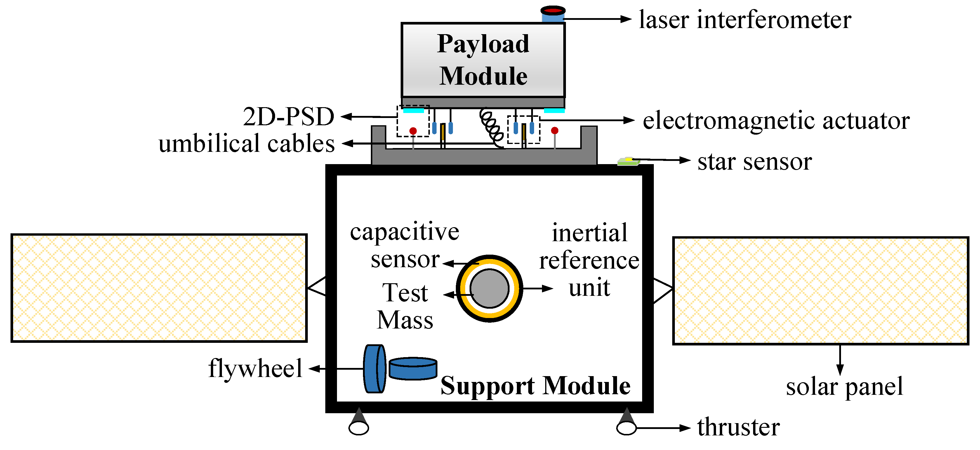
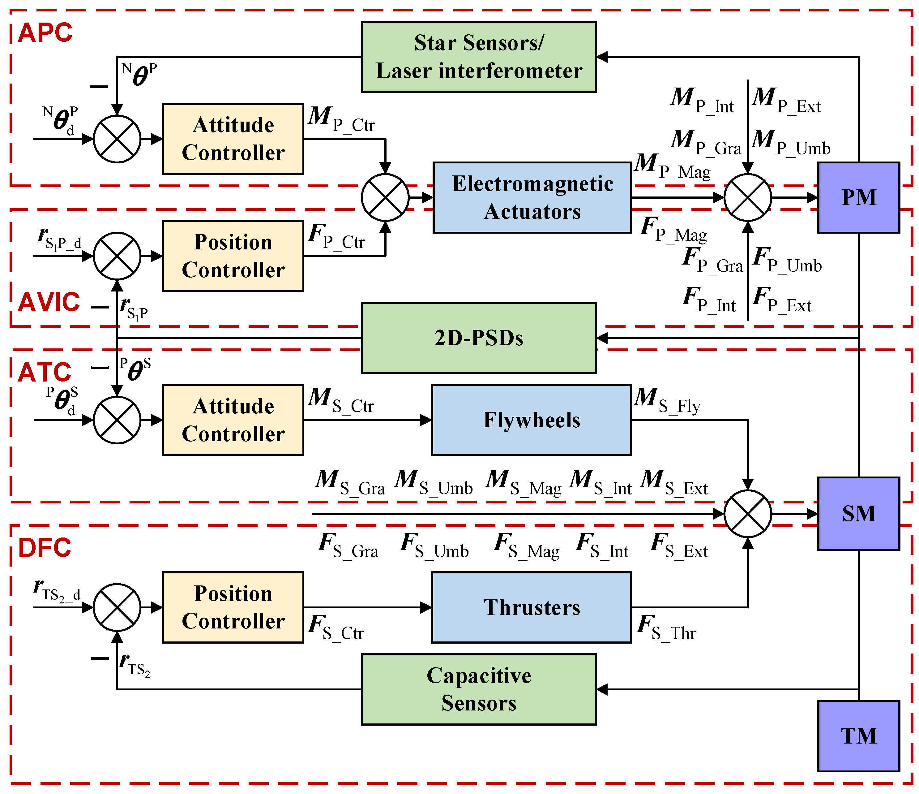
2. Control System Configuration
3. Disturbance Attenuation and Pointing Control System Design
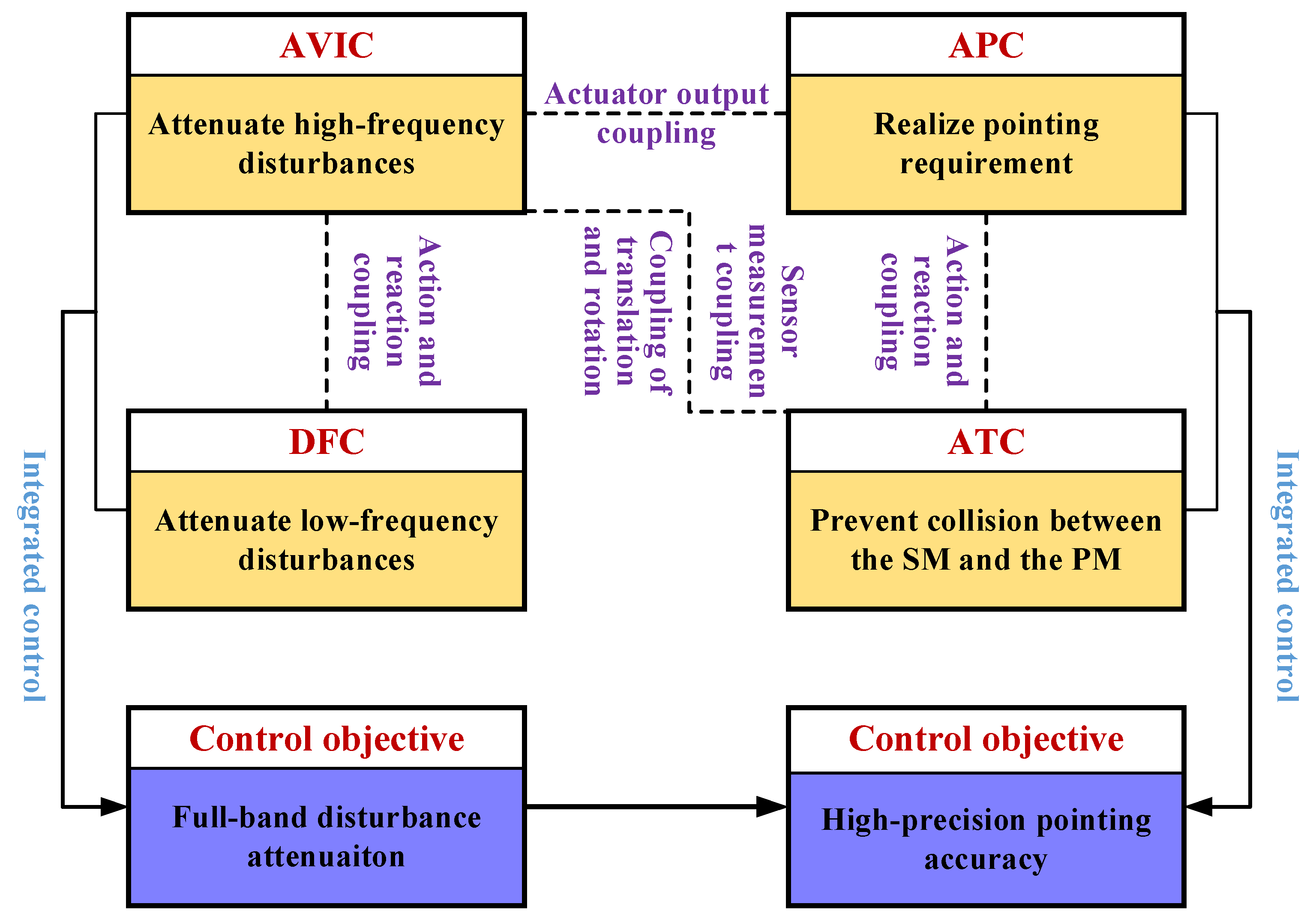
3.1. Integrated Control Strategy and Coupling Analysis
3.2. Decoupling and Feedback Design
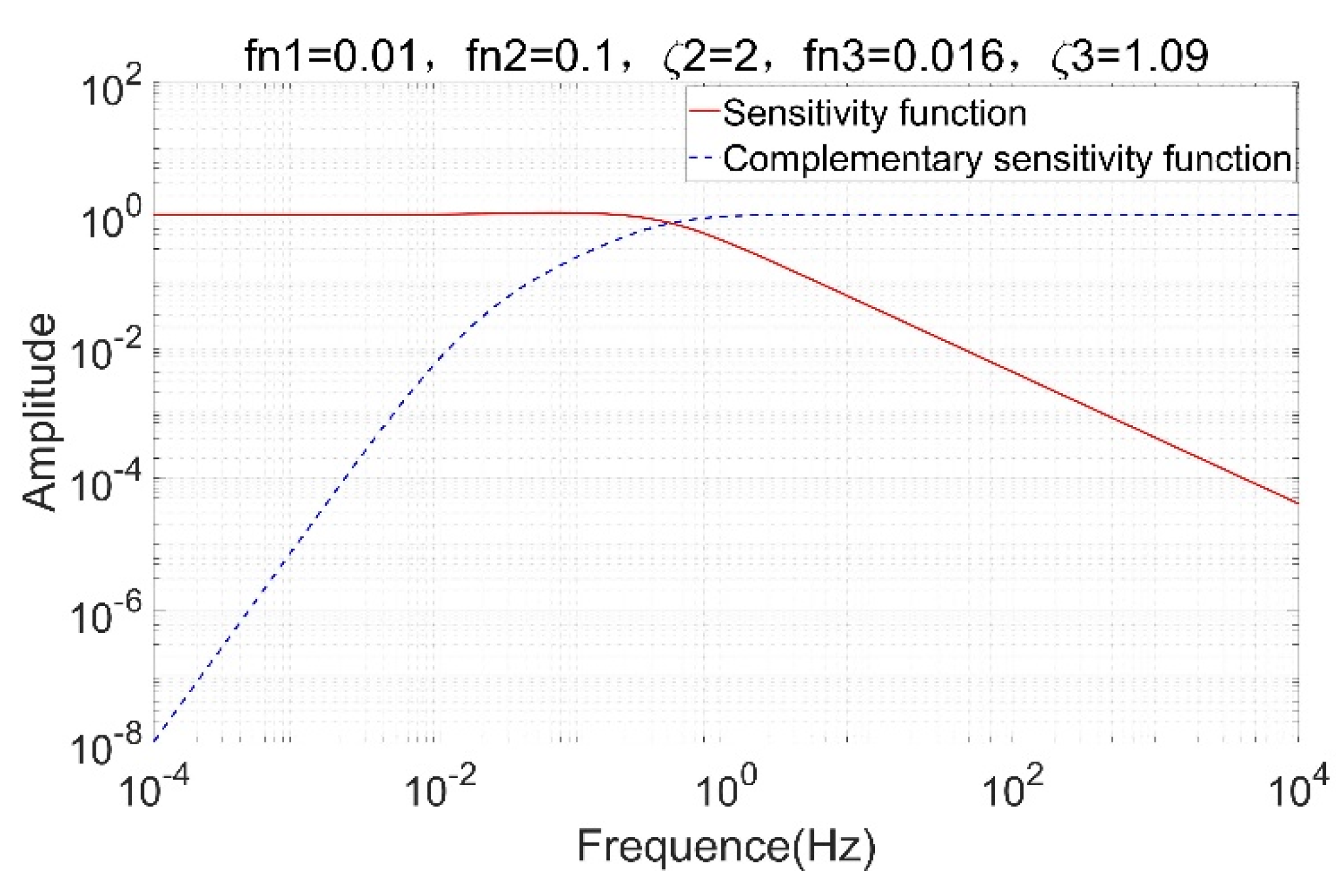
3.3. Amplitude-Frequency Response Analysis and Control Bandwidth Design
4. Numerical Simulations
4.1. Stability of Integrated Control
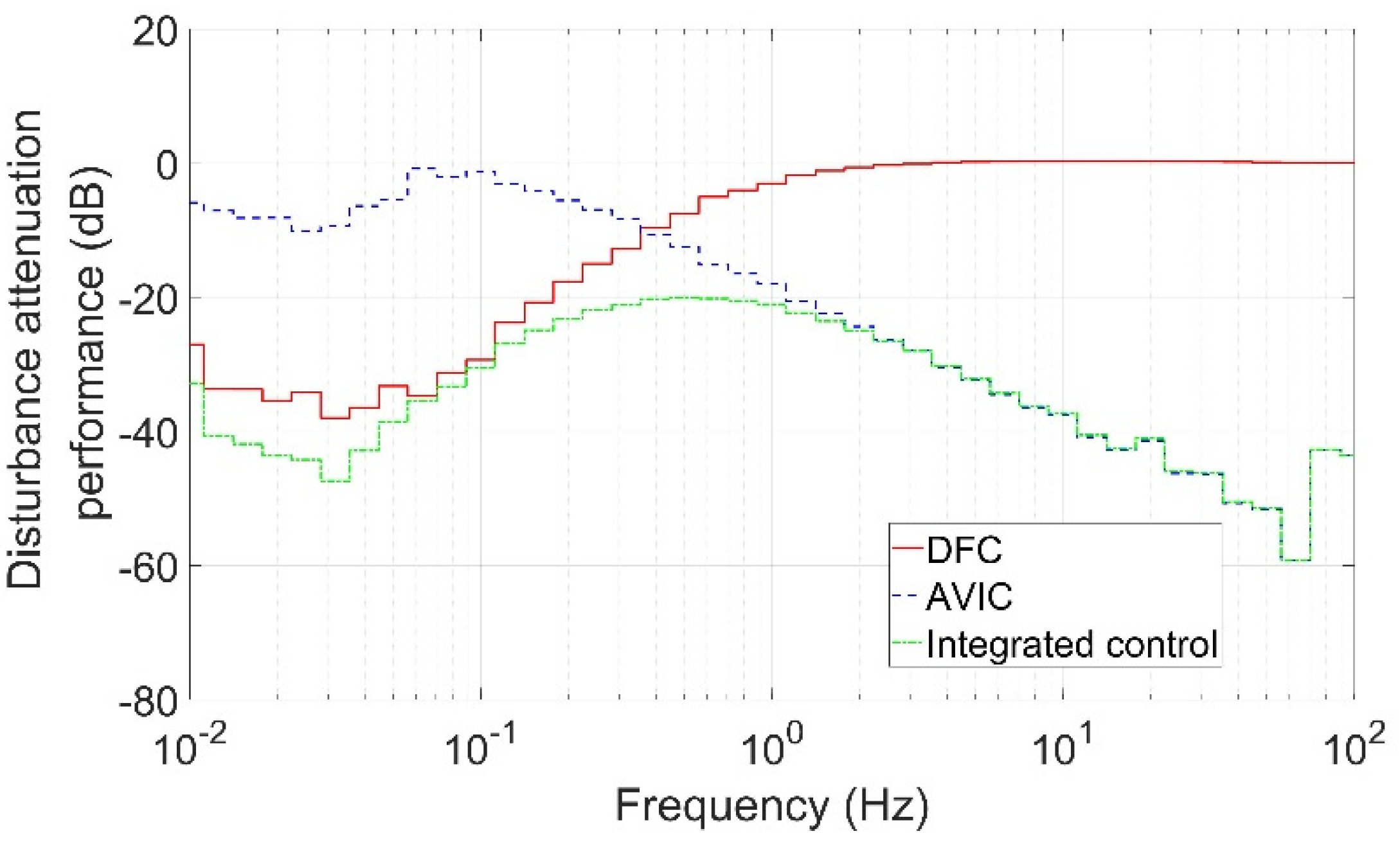
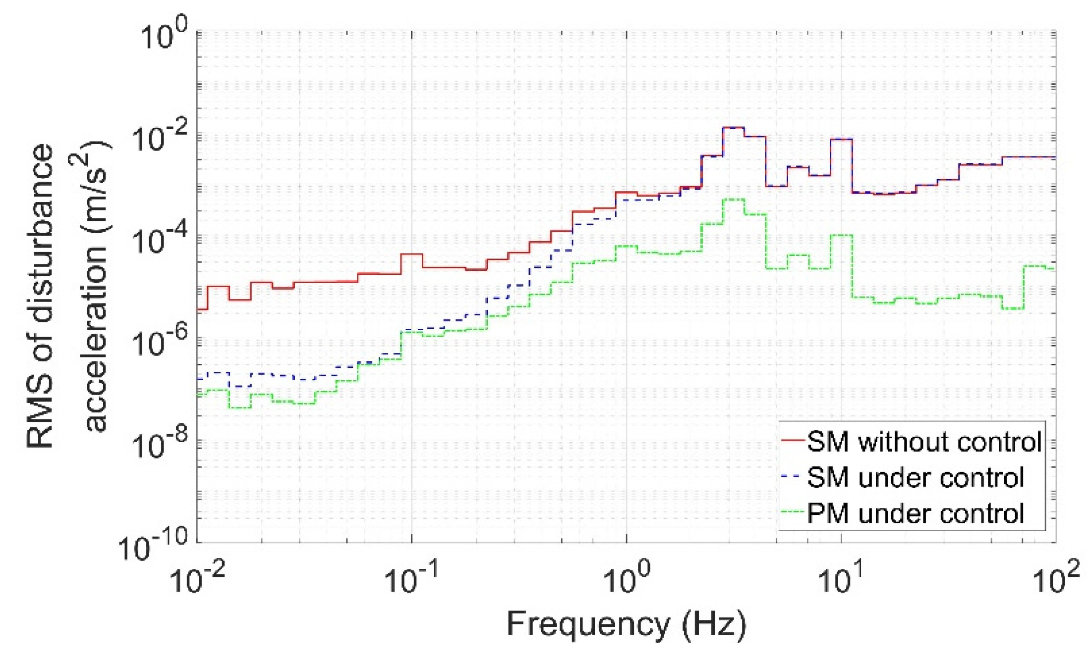
4.2. Disturbance Attenuation Performance
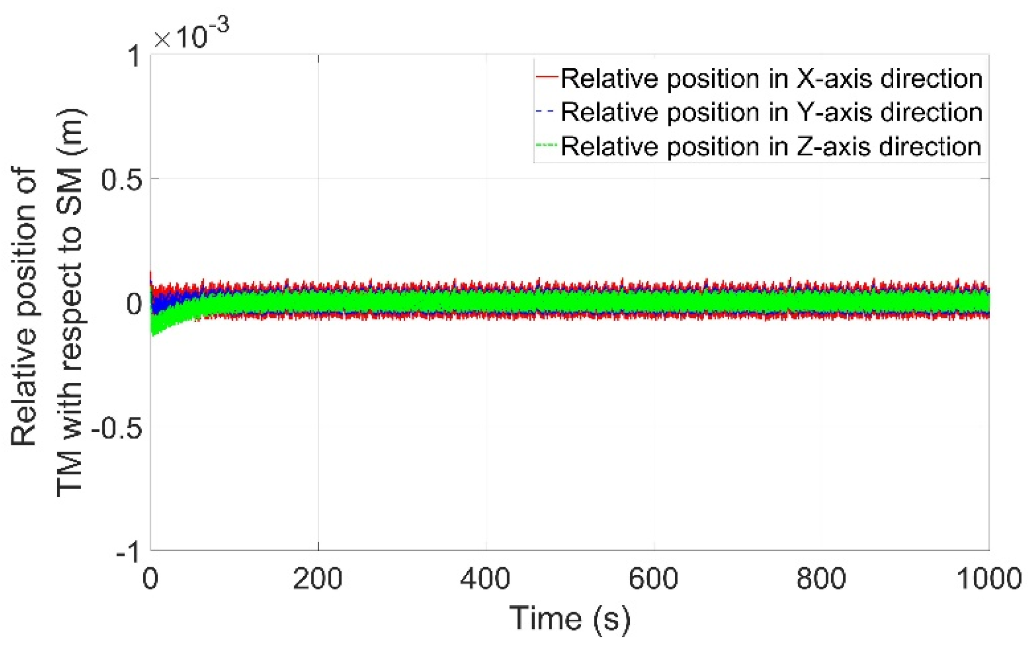
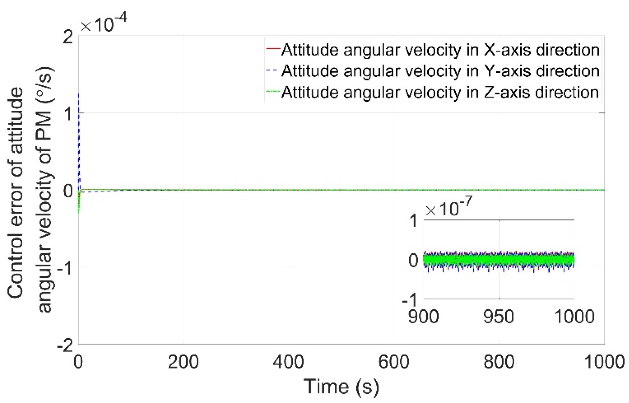
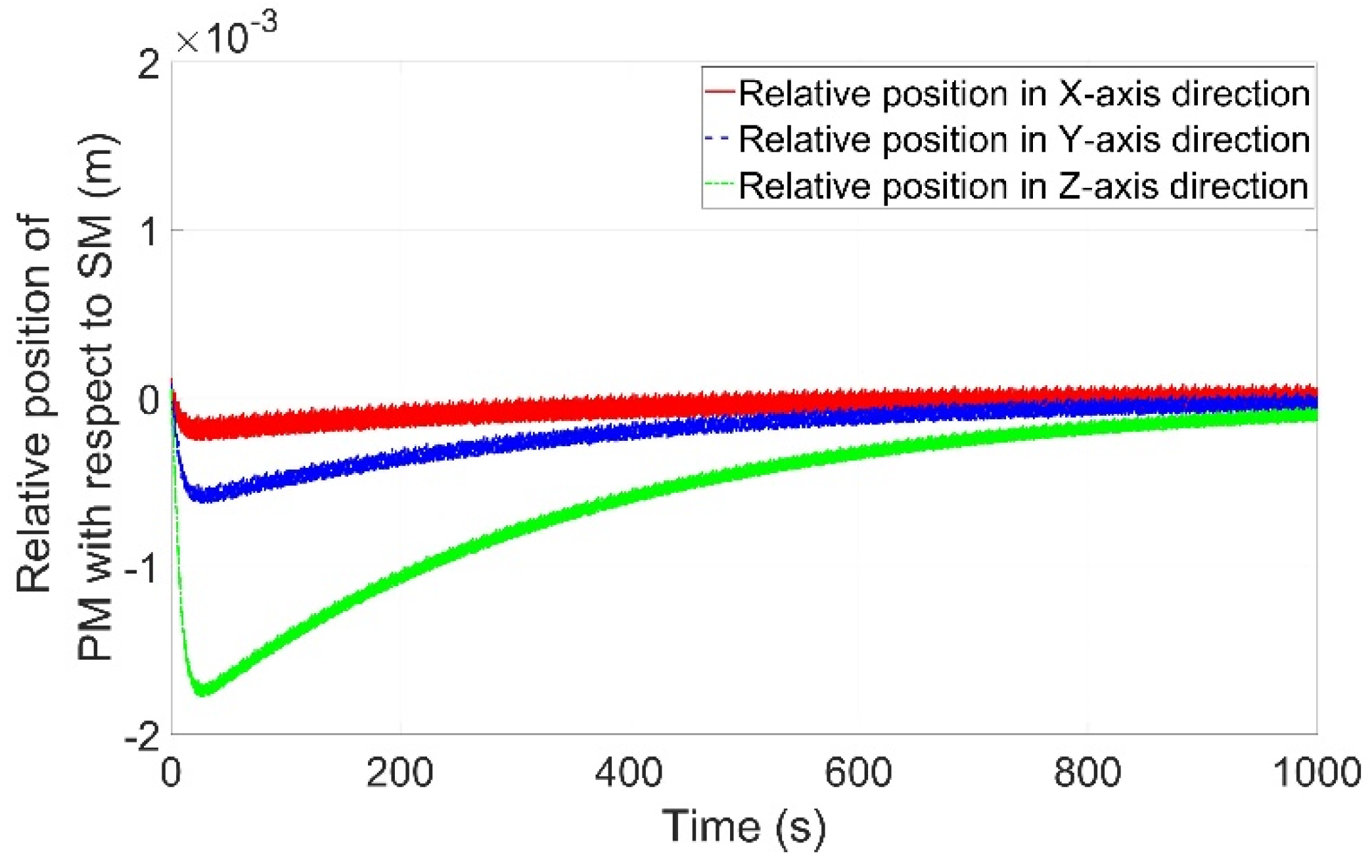
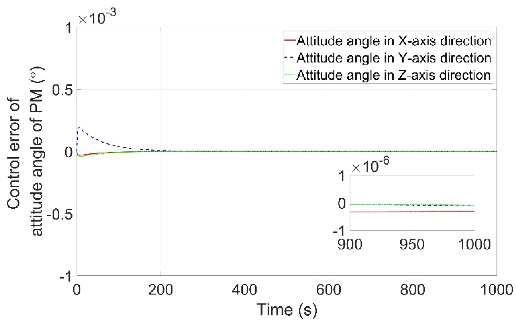
4.3. Pointing Accuracy and Stability
5. Conclusions
Author Contributions
Funding
Institutional Review Board Statement
Informed Consent Statement
Data Availability Statement
Conflicts of Interest
References
- Pedreiro, N. Spacecraft architecture for disturbance-free payload. J. Guid. Control Dyn. 2003, 26, 794–804. [Google Scholar] [CrossRef]
- Dewell, L.D.; Tajdaran, K.; Bell, R.M.; Liu, K.; Bolcar, M.R.; Sacks, L.W.; Crooke, J.A.; Blaurock, C. Dynamic stability with the disturbance-free payload architecture as applied to the Large UV/Optical/Infrared (LUVOIR) mission. In Proceedings of the 2017 SPIE, San Diego, CA, USA, 6–10 August 2017; p. 103980B. [Google Scholar] [CrossRef]
- Bian, Z.Q.; Cai, C.S.; Lv, W.; Shen, Y.L. High Accuracy and High Stability Control Technology of Remote Sensing Satellite. Aerosp. Shanghai 2014, 31, 24–38. [Google Scholar] [CrossRef]
- Bronowicki, A.J. Vibration Isolator for Large Space Telescopes. J. Spacecr. Rocket. 2006, 43, 45–53. [Google Scholar] [CrossRef]
- Kong, Y.; Huang, H. Performance enhancement of disturbance-free payload with a novel design of architecture and control. Acta Astronaut. 2019, 159, 238–249. [Google Scholar] [CrossRef]
- Wu, C.; Kong, X.; Liu, Y.; Chen, Z. Coupling characteristics analysis for the disturbance free payload spacecraft. Acta Astronaut. 2017, 138, 407–416. [Google Scholar] [CrossRef]
- Kong, X.; Wu, C.; Li, H.; Yang, Z. Effect of back electromotive force on accurate pointing of disturbance-free-payload spacecraft. J. Natl. Univ. Def. Technol. 2019, 41, 75–81. [Google Scholar] [CrossRef]
- Zhou, J.; Liu, L.; Wang, Z.; Lil, J.; Deng, Y. On Pointing Accuracy and Pointing Stability of Disturbance-Free Payload Using Umbilical Connection. In Proceedings of the 37th Chinese Control Conference, Wuhan, China, 25–27 July 2018. [Google Scholar]
- Yang, H.; Liu, L.; Yun, H.; Li, X. Modeling and collision avoidance control for the Disturbance-Free Payload spacecraft. Acta Astronaut. 2019, 164, 415–424. [Google Scholar] [CrossRef]
- Fan, T.; Ren, W.; Li, Z. A Stiffness Testing System for the Umbilical of the Active Vibration Isolation System. Mech. Sci. Techn. Aerosp. Eng. 2016, 35, 1144–1148. [Google Scholar] [CrossRef]
- Wu, Q.; Liu, B.; Cui, N.; Yue, H.; Liu, R. Dynamic analysis of umbilical cables for maglev vibration isolation systems. AIAA J. 2019, 57, 1752–1762. [Google Scholar] [CrossRef]
- Lange, B. The drag-free satellite. AIAA J. 2011, 2, 1590–1606. [Google Scholar] [CrossRef]
- Tao, J.; Zhang, T. Relative position and attitude control for drag-free satellite with prescribed performance and actuator saturation. Trans. Nanjing Univ. Aeronaut. Astronaut. 2019, 36, 617–627. [Google Scholar] [CrossRef]
- Lian, X.; Zhang, J.; Wang, J.; Wang, P.; Lu, Z. State and disturbance estimation for test masses of drag-free satellites based on self-recurrent wavelet neural network. Adv. Space Res. 2020, 67, 3654–3666. [Google Scholar] [CrossRef]
- Rodrigues, M.; Robert, A.; Touboul, P.; Metris, G.; Prieur, P.; Cipolla, V.; Boulanger, D.; Chhun, R.; Christophe, B.; Guidotti, P.Y. Microscope satellite and its drag-free and attitude control system. Class. Quantum Grav. 2022, 39, 204003. [Google Scholar] [CrossRef]
- Jin, T.; Kang, G.; Cai, J.; Jia, S.; Yang, J.; Zhang, X.; Zhang, Z.; Li, L.; Liu, F. Integrated Control Scheme for an Improved Disturbance-Free Payload Spacecraft. Aerospace 2022, 9, 571. [Google Scholar] [CrossRef]


| Loop | Sensor | Actuation | Objective |
|---|---|---|---|
| APC | Star sensors, Laser interferometer | Electromagnetic actuators | Realize pointing requirement |
| ATC | 2D-PSDs | Flywheels | Prevent collision |
| AVIC | 2D-PSDs | Electromagnetic actuators | Attenuate high-frequency disturbances |
| DFC | Capacitive sensors | Thrusters | Attenuate low-frequency disturbances |
| Loop | Value |
|---|---|
| APC | |
| ATC | |
| AVIC | |
| DFC |
Disclaimer/Publisher’s Note: The statements, opinions and data contained in all publications are solely those of the individual author(s) and contributor(s) and not of MDPI and/or the editor(s). MDPI and/or the editor(s) disclaim responsibility for any injury to people or property resulting from any ideas, methods, instructions or products referred to in the content. |
© 2023 by the authors. Licensee MDPI, Basel, Switzerland. This article is an open access article distributed under the terms and conditions of the Creative Commons Attribution (CC BY) license (https://creativecommons.org/licenses/by/4.0/).
Share and Cite
Jin, T.; Kang, G.; Cai, J.; Jia, S.; Yang, J.; Zhang, X.; Zhang, Z.; Li, L.; Liu, F. Disturbance Attenuation and Pointing Control System Design for an Improved Disturbance-Free Payload Spacecraft. Aerospace 2023, 10, 530. https://doi.org/10.3390/aerospace10060530
Jin T, Kang G, Cai J, Jia S, Yang J, Zhang X, Zhang Z, Li L, Liu F. Disturbance Attenuation and Pointing Control System Design for an Improved Disturbance-Free Payload Spacecraft. Aerospace. 2023; 10(6):530. https://doi.org/10.3390/aerospace10060530
Chicago/Turabian StyleJin, Ting, Guohua Kang, Jian Cai, Shaoxia Jia, Jinghua Yang, Xinghua Zhang, Zhenhua Zhang, Long Li, and Fangfang Liu. 2023. "Disturbance Attenuation and Pointing Control System Design for an Improved Disturbance-Free Payload Spacecraft" Aerospace 10, no. 6: 530. https://doi.org/10.3390/aerospace10060530
APA StyleJin, T., Kang, G., Cai, J., Jia, S., Yang, J., Zhang, X., Zhang, Z., Li, L., & Liu, F. (2023). Disturbance Attenuation and Pointing Control System Design for an Improved Disturbance-Free Payload Spacecraft. Aerospace, 10(6), 530. https://doi.org/10.3390/aerospace10060530