Abstract
This work presents a method to utilise only haptic information in successfully completing a threaded insertion. We derive the insights for this task from human demonstrations and highlight the sufficiency of haptic data in this application, without the use of vision-based feedback or complex geometric models. We begin with human demonstrations to characterize the haptic artefacts that arise while employing backspinning motion. Force and motion data reveal a repeatable axial force transient (a spike); this signature repeats periodically for each revolution and appears for both internally and externally threaded parts of varying sizes. We then validate the same haptic cue on a robot arm. Finally, we use this insight in an end-to-end bulb insertion pipeline. A custom mechanical adapter ensures a secure grasp to enable autonomous threaded insertion of the bulb. Experimental results confirm that the force-based approach enables robust and repeatable insertion, demonstrating that haptic cues alone are sufficient for everyday threaded assemblies.
1. Introduction
Threaded fasteners, such as those used in jars, bottle caps, and bulbs, are ubiquitous in daily objects. Inevitably, to achieve engagement, information regarding the position, orientation, and force between the mating parts is essential. In this work, relying on the intuition that haptic cues encode kinematic/geometric information of the objects in physical interaction [1,2], we study the threaded insertion of two mating parts solely based on interaction forces. These forces provide a reliable cue in terms of the onset of thread engagement that produces characteristic axial force signatures reflecting the evolving contact between the mating parts. By leveraging these force signatures, we establish a purely haptic mechanism for detecting thread engagement, demonstrating that haptic cues alone can reliably guide the insertion process.
Threaded assembly has long been recognized as a force-critical process in precision automation, where small variations in forces provide essential information about thread engagement [3]. Moreover, the early stages of thread engagement involve complex and unpredictable interactions between mating threads, making the process prone to faults such as cross-threading and jamming that can lead to failures [4]. In this work, we adopt a human-inspired approach where haptic cues captured through force/torque (F/T) sensors are used to detect thread engagement. By focusing solely on the forces generated during insertion, we avoid the need for visual tracking, geometric models, or vision-based feedback or prior information about thread geometry, allowing for a more robust and reliable threaded insertion.
Significant research has been carried out towards haptic manipulation and contact-rich tasks, where haptics plays an important role in activities like screwing and threaded fastening assembly [5,6,7], as well as in bulb turning [8]. However, these approaches make use of vision-based object detection, time-consuming demonstration learning, or specialized gripper design to carry out the task. Prior work has explored threaded assembly with F/T sensing in different ways. For instance, the relation between kinematic thread engagement models and forces of interaction has been examined in [9]. Other studies focused on unscrewing caps of various objects with a bimanual robot using F/T sensors on each arm to enable more reactive control [10], or on human–robot interaction systems for tasks such as replacing a street lamp using full-body tracking [11]. Meanwhile, kinesthetic demonstrations have been used to teach a robot to unscrew a light bulb via movement primitives [12], while quasi-static approaches with F/T sensing for adjustment and alignment have been applied to assemble both threaded and non-threaded rounded parts [13]. Finally, task-based compliance control with force feedback has been demonstrated for dual-arm bottle screw manipulation, focusing on motion planning [14].
Even though these works employ F/T sensing, they mostly rely on elaborate models, complex demonstrations or vision-based feedback. In contrast, our approach is human-centred and model-agnostic to study the manipulation strategies used during threaded insertion by employing the backspinning technique. In this technique, the operator rotates the threaded part in the reverse direction while maintaining contact, ensuring that a significant portion of the contact force is in the direction of the thread axis [9], producing distinctive and repeatable haptic signatures that indicate engagement. By recording both force and orientation data during human demonstrations, we study the haptic artefact occurring between the two mating parts during backspinning. These key haptic insights obtained from the study are then used to implement bulb insertion. For this, we use a 7-DoF manipulator equipped with an adapter to securely grasp a bulb and successfully complete bulb insertion. We focus solely on the interaction forces, which prove to be a reliable indicator of thread engagement.
The rest of the paper is organized as follows: Section 2 details the experimental setup and protocol for the threaded insertion task performed by humans, along with key haptic insights obtained. In Section 3, we describe how these insights were applied to a robotic bulb insertion task and report the corresponding results. In Section 4, we discuss the key findings and contributions of this work and, finally, Section 5 provides a conclusion to this work.
2. Haptic Characterization of Threaded Insertion by Humans
This section details the experimental setup and protocol used to characterize forces during threaded insertion. The objective is to identify key haptic artefacts while the participant executes the task (using the backspinning technique) rather than relying on complex vision systems. To ensure a successful threaded insertion without jamming or cross-threading, the process typically involves two distinct phases: first, backspinning, which involves rotating the threaded body in the direction of thread disengagement to infer, through the force domain, the orientation of the threaded body with respect to the threaded base [9]. Once the alignment cue is detected, forward rotation can begin smoothly, allowing the threads to mesh without interference or excessive force.
Typically, the threaded components could be of two types: internal or external threads, with varying thread parameters [15,16]. The current section details the experimental setup and protocol, the tools used and the analysis employed to discern the haptic artefacts during threaded insertion (refer to the frames defined in Figure 1).
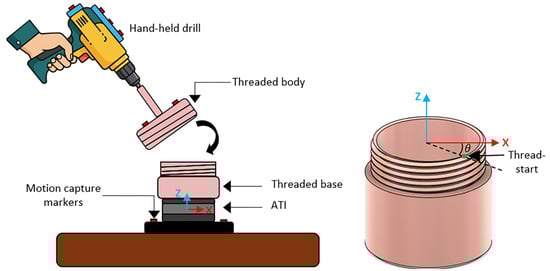
Figure 1.
Schematic representation of the experimental setup showing F/T sensor and motion capture markers to measure task dynamics and kinematics.
2.1. Experimental Setup and Protocol
A schematic representation of the experimental setup is illustrated in Figure 1. The purpose of the setup is to study how a human infers thread engagement through haptic cues only. The setup comprises a hand-held drill that the participant uses to perform the task. The drill is chosen to simulate the rotational motion and draw an equivalence to the robot end-effector. This will also help eliminate any haptic artefacts that may arise from grasping and re-grasping of the threaded body by the participant’s hand (which is a common practice employed during thread engagement and disengagement by humans). This threaded body (referred to as the body henceforth) is rigidly attached to the drill. The corresponding threaded base (referred to as base henceforth) is fixed through an ATI Mini40 F/T sensor to the table to monitor interaction forces during thread engagement. Phasespace motion capture system is used to track the position and orientation of each component. There are 8 markers mounted on the body, 4 markers attached to the base, and 8 markers attached to the drill. For the purpose of this experiment, we designed two sets of right-handed threaded components with a single thread start, featuring M50×3 internal threads and M55×4 external threads on the base.
The experimental procedure only dictates that the human participant picks up the drill and adjusts its orientation and position, while applying the backspinning technique to identify a reliable haptic cue that indicates the appropriate time instant to initiate thread engagement without jamming (see Figure 2).
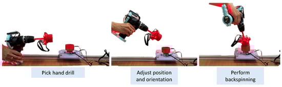
Figure 2.
Phases of the experiment from picking up the hand drill to successful alignment of the body onto the base.
2.2. Experimental Results
In our study, two participants completed two trials each on both the internally and externally threaded components. The corresponding results for the two sets of threaded components are presented in Figure 3 and Figure 4. We can observe repeated spikes in , which act as haptic cues during the insertion process (see Figure 3a and Figure 4a). These spikes occur consistently once per revolution, indicating a periodic interaction pattern that can be used to guide the operator’s actions. Once such a spike is detected, it serves as a reliable signal to initiate forward rotation and proceed with thread engagement.
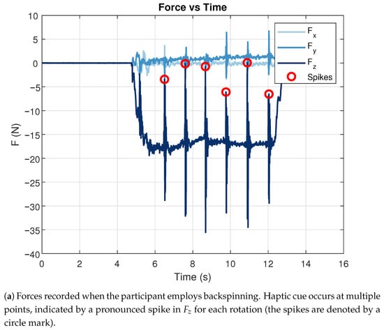
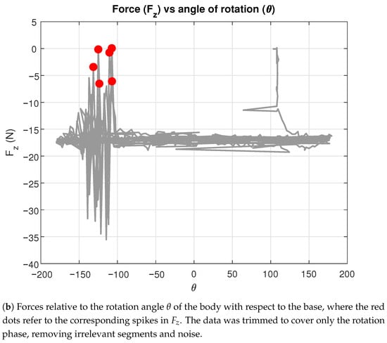
Figure 3.
Interaction forces measured during thread insertion with internally threaded components.
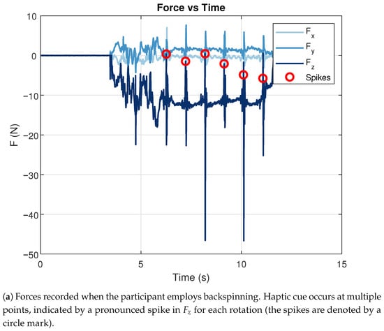
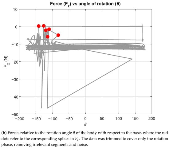
Figure 4.
Interaction forces measured during the threaded insertion task with externally threaded components.
Figure 3b and Figure 4b represent the forces from the same trial expressed in terms of the rotation angle, , of the body relative to the base. However, there is a variation in the recorded location of the spike due to inaccuracies and non-ideal surface finish in the 3D-printed thread construction. Nevertheless, a clear and repeatable pattern of force spikes can be observed for each rotation, providing a reliable cue for identifying when engagement should be initiated. At this instance, the body and base are positioned such that the threads can begin to mesh smoothly, and the backspinning motion serves to reveal this cue without risk of cross-threading or jamming.
3. Robot-Based Bulb Insertion
In this section, we present a robotic implementation of a threaded insertion task, using haptic cues to complete an insertion. These haptic cues are inferred from the analysis of the data from the experiments in Section 2. This implementation was undertaken in two stages:
- Backspinning Test—to characterize the forces during backspinning by the robot and ensure the detection of force artefacts corresponding to the thread engagement; and
- Robot Bulb Insertion—to demonstrate an end-to-end robot-based bulb insertion pipeline: grasping a bulb, probing for the haptic cue via force feedback, and completing insertion.
3.1. Backspinning Test
For the Backspinning Test, we adapted the threaded body from Section 2 to be able to mount to the robot end-effector. The corresponding threaded base was mounted on the table through a F/T sensor. The objective of this test is to identify and characterize the haptic cues that occur during backspinning.
3.1.1. Experimental Setup
We use a Kinova Gen3 7-DoF arm with a 3D-printed threaded body (single thread start) mounted rigidly onto the end-effector, and the corresponding threaded base fixed on the table through the ATI Mini40 F/T sensor (Figure 5). The threaded base was placed at a known pose relative to the robot base. The body was rigidly attached to the end-effector of the robot to eliminate any other haptic features from the data, such as those that may arise from an unsecured grasp of the objects.
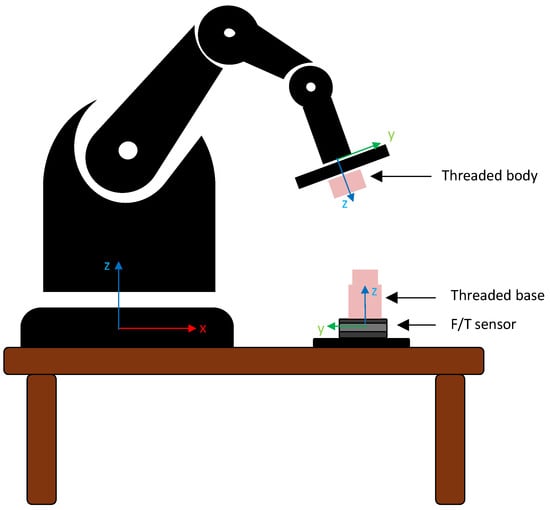
Figure 5.
Schematic representation of the setup for backspinning test.
3.1.2. Experimental Protocol
The protocol involves three distinct phases (see Figure 6). In the first phase, the robot moves to a pre-contact pose above the base. Followed by this, the robot descends until the F/T sensor measures a contact force of , ensuring contact between the body and the base. This threshold is based on observations from the human study, where we measured the typical vertical pre-load during backspinning. Once the force threshold is met, the robot performs backspinning at a constant speed and with a constant downward force, heuristically chosen, spanning four full turns of the body.
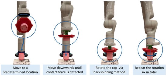
Figure 6.
Phases in the backspinning test from moving to a determined location to completing four rotations.
3.1.3. Empirical Observations and Analysis
Figure 7 shows recorded by the F/T sensor together with the end-effector height z. Before contact, ; once contact occurs, becomes negative due to the applied pre-load. During backspinning, distinct spikes in appear once per revolution, consistent with the single-lead thread geometry. Each spike coincides with a sudden drop in the end-effector height z, indicating that the threads of both parts are properly positioned for engagement.
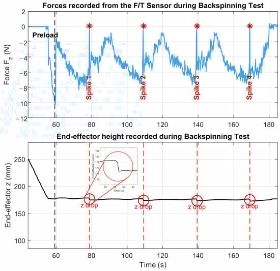
Figure 7.
Results from Backspinning Test. Top: Vertical force recorded by the F/T sensor during backspinning. Distinct spikes occur once per revolution, providing a clear haptic cue. Bottom: End-effector vertical position z, showing sudden drops that coincide with the force spikes, indicating the relative orientation of the threaded body and base at which thread engagement can be initiated without jamming. Together, these signals confirm that the haptic cue is consistently detectable in the robot, matching observations from human demonstrations.
These spikes acting as reliable haptic cues are similarly observed in the human experiments (see Figure 3 and Figure 4). The agreement between human and robot trials confirms that provides a robust metric, motivating the use of this feature in Section 3.2.
3.2. Robot Bulb Insertion
Once the haptic features are validated in the Backspinning Test (Section 3.1), we conduct the Robot Bulb Insertion, where we integrate this haptic cue into a full manipulation pipeline. For this, we designed an adapter that enables secure grasping of a bulb with a standard two-finger gripper while constraining relative motion. The robot approaches the socket, searches for a haptic cue via backspinning, while monitoring changes in force, and triggers insertion upon detecting the haptic cue.
3.2.1. Experimental Setup and Mechanical Adapter Design
In this experiment, we modify the previous setup for an end-to-end bulb insertion task with a robot. Specifically, we include the standard robotic gripper Robotiq 2F-85) with interchangeable custom mechanical adapters. The adapters are used to grasp a 3D-printed bulb to insert into its corresponding socket with compatible threads.
To ensure secure grasping of the bulb during manipulation, we developed an orientation-locking mechanical adapter. The adapter, illustrated in Figure 8, incorporates three key features that align the bulb with respect to the robot end-effector and constrain it relative to the gripper. Feature A consists of a contoured cavity that seats the bulb, restricting translations along the end-effector x, y, and z axes, while also constraining rotation about its y-axis. Feature B provides lateral support through side protrusions that specifically limit rotation about the end-effector x-axis. Feature C is the high-friction 3M Temflex cloth tape applied on the contact surfaces of Feature A to constrain rotation about the z-axis of the end-effector. Together, these features mechanically lock the bulb in both position and orientation. Importantly, the adapter is compatible with standard two-fingered parallel-jaw grippers.
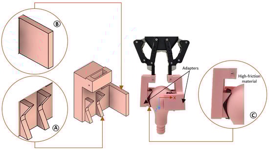
Figure 8.
Customized adapter with Feature A (contoured cavity), Feature B (side protrusions), and Feature C (high-friction tape), which together enable secure and stable bulb manipulation.
3.2.2. Experiment Protocol
The robot executes four phases while relying on haptic cues to progress between phases.
- Phase 1: Move to grasp the bulb.
The end-effector is moved from home position to a pre-grasp pose near the bulb, as seen in Figure 9. The bulb is then grasped securely through the mechanical adapter.
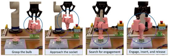
Figure 9.
Robot Bulb Insertion: grasping the bulb, moving to the target, backspinning, start engaging the thread.
- Phase 2: Retract and approach the threaded socket.
After grasping the bulb, the robot retracts and moves towards the threaded socket. Contact is considered detected when crosses a threshold:
Note that the value of is derived from the human study results presented in Section 2, where it corresponds to the typical vertical pre-load during backspinning. Once this condition is satisfied, a flag is set, and the robot transitions to backspinning.
- Phase 3: Backspinning and haptic cue detection.
From the contact pose, the robot performs backspinning about the tool z-axis at a constant speed while pressing the bulb against the socket, ensuring contact. is monitored to detect spikes that indicate the haptic cue.
Filtering: To reduce noise in the force signal, we implement a first-order infinite impulse response (IIR) low-pass filter, following the formulation in [17]. The raw signal is smoothed as
where k denotes the discrete-time sample index, is the sampling period ( Hz) and Hz is the cutoff frequency.
Haptic cue detection: Over a rolling window of samples corresponding to an angular span , the force range is identified as
A spike is determined to be present in the window when ; in our runs we used N, chosen based on the backspinning test (see Section 3.1.3, where haptic cues consistently produced force spikes exceeding 5 N). The first such spike is taken as a haptic cue signaling that thread engagement is ready to be initiated. Another flag is then raised, triggering a transition to the next phase.
- Phase 4: Engage, insert, and release.
After detecting the haptic cue, the robot switches to engage rotation. A fixed rotation of one full turn is commanded to ensure secure attachment, after which the gripper is opened.
3.2.3. Results and Observations
Figure 10 shows measured at the socket during the robot trial. After the bulb is grasped with the mechanical adapters, the robot retracts and moves towards the socket. Contact is registered once the pre-load condition in Equation (1) is satisfied, and a flag is raised to initiate Phase 3.
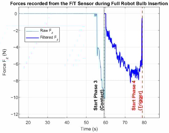
Figure 10.
Force data in End-to-End Robot Bulb Insertion. The black dash-dot line marks the start of Phase 3 (contact), detected when N. The red dashed line marks the start of Phase 4, triggered when the haptic cue detector identifies a spike in .
In Phase 3, the robot performs backspinning while lightly pressing the bulb against the socket. The signal is filtered using Equation (2), and once the range condition is met (Equation (3)), another flag is raised to indicate that thread engagement can be initiated. This event triggers Phase 4, in which the robot switches to engage rotation.
The trial confirms that the haptic cue identified in the human experiments can be reliably detected by the robot as well, enabling autonomous transition from probing to insertion.
4. Discussion
In this work, we investigated threaded insertion through human and robot-based experiments to examine how haptic cues alone can enable reliable thread engagement. In the following sections, we highlight key insights regarding their generality despite varying thread specifications, compliance in axial alignment, and directions for future work.
4.1. Force Signatures During Thread Engagement
The spikes in force arise from small but abrupt motion that occurs at each 360° rotation of the thread. Furthermore, the number of spikes in is the same as the number of thread starts (In this case, it is one). This abrupt motion leads to an impulse-like axial force, consistently observed across human and robot-based trials. Such spikes are an inherent outcome of thread engagement and provide a reliable and repeatable haptic cue.
4.2. Generality Across Thread Types and Sizes
These characteristic force signatures were found to be visible irrespective of the thread type and size. This is evident from the human demonstration where we used two distinct threaded bases—one internally (M50 × 3) and one externally (M55 × 4) threaded, while for the robot-based trials, a standard bulb socket thread was used. Despite these variations, the same haptic features emerged, indicating that the proposed method is not dependent on a specific thread geometry. Although a full study of the influence of thread size is beyond the scope of this work, our findings across these varied thread types suggest that the approach is scalable and has the potential to generalize to broader assembly scenarios where thread specifications may vary.
4.3. Role of Compliance in Axial Alignment
While axial misalignment can in principle be detected through the lateral forces and ( and should be zero when there is no axial misalignment), it should be emphasized that with the compliance-based control adopted in this study, only an estimate of the base position and orientation is necessary. The inherent compliance of the controller provides sufficient tolerance to accommodate misalignments arising from estimation errors. Nonetheless, to improve robustness, the incorporation of an active axial alignment strategy could prove beneficial. The authors intend to explore such approaches in future work.
4.4. Future Work
Building on the findings presented here, several avenues for future research are identified. Preliminary analysis suggests a correlation between the wrench axis and the orientation of the threaded body. This points toward a deeper relationship between object orientation and haptic signatures, which merits systematic investigation.
Furthermore, the present analysis lays the foundation for real-time alignment correction. In cases where correction is required (e.g., due to base misalignment, fixture tolerances, or initial thread mismatch), the robot could apply small, bounded tilt adjustments to recover alignment online. Extending this idea, the haptic cues identified here could be incorporated into a library of force–action signatures, enabling robots to monitor interaction forces in real time and adapt their actions without relying on vision or detailed geometric models. Such an approach could serve as a foundational step for frameworks like the one in [18].
5. Conclusions
This work explored threaded insertion with a focus on human strategies for thread engagement via backspinning. Through these demonstrations, we identified force patterns that consistently indicate reliable haptic cues referring to the time instant at which thread engagement can be initiated without jamming. These insights were then used to implement a robotic bulb insertion experiment, with the robot arm equipped with a custom adapter to ensure secure grasping. The results show that force-based cues observed during human-led insertions can be effectively transferred to robotic execution.
Our method relies solely on haptic information and haptic cues, without the need for advanced modeling or vision. In contrast to many approaches in the literature that depend on precise geometric models or visual tracking, our approach highlights the sufficiency of simple force-based sensing for a robust threaded insertion task.
Author Contributions
Conceptualization, G.G., S.R.K. and D.C.; experiment design, G.G., K.I.W., S.R.K. and S.S.; data collection and curation, G.G., K.I.W. and S.R.K.; analysis, G.G., K.I.W., S.R.K., S.S. and S.H.T.; original draft preparation, G.G., K.I.W. and S.R.K.; review and editing, G.G., K.I.W., S.R.K., S.S., S.H.T., Y.W. and D.C. All authors have read and agreed to the published version of the manuscript.
Funding
This research was conducted under project WP3 within the Delta-NTU Corporate Lab with funding support from A*STAR under its IAF-ICP programme (Grant no. I2201E0013) and Delta Electronics Inc.
Institutional Review Board Statement
Not applicable.
Informed Consent Statement
Not applicable.
Data Availability Statement
Data will be available at request.
Conflicts of Interest
Author Yongjun Wee was employed by the company Delta Electronics Inc. The authors declare that the research was conducted in the absence of any commercial or financial relationships that could be construed as a potential conflict of interest. The authors declare no conflicts of interest.
References
- Golani, G.; Turlapati, S.H.; Yang, L.; Ariffin, M.Z.B.; Campolo, D. Robotic valve turning: Axial misalignment estimation from reaction torques. In Proceedings of the 2024 IEEE/RSJ International Conference on Intelligent Robots and Systems (IROS), Abu Dhabi, United Arab Emirates, 14–18 October 2024; pp. 5275–5280. [Google Scholar]
- Turlapati, S.H.; Campolo, D. Towards haptic-based dual-arm manipulation. Sensors 2022, 23, 376. [Google Scholar] [CrossRef] [PubMed]
- Dunne, B.J. Precision Torque Control for Threaded Part Assembly. Ph.D. Thesis, Massachusetts Institute of Technology, Cambridge, MA, USA, 1986. [Google Scholar]
- Jia, Z.; Bhatia, A.; Aronson, R.M.; Bourne, D.; Mason, M.T. A survey of automated threaded fastening. IEEE Trans. Autom. Sci. Eng. 2018, 16, 298–310. [Google Scholar] [CrossRef]
- Li, F.; Bai, Y.; Zhao, M.; Fu, T.; Men, Y.; Song, R. Research on Robot Screwing Skill Method Based on Demonstration Learning. Sensors 2023, 24, 21. [Google Scholar] [CrossRef] [PubMed]
- Dharmara, K.; Monfared, R.P.; Ogun, P.S.; Jackson, M.R. Robotic assembly of threaded fasteners in a non-structured environment. Int. J. Adv. Manuf. Technol. 2018, 98, 2093–2107. [Google Scholar] [CrossRef]
- Chen, J.; Liu, Z.; Xu, J.; Yang, C.; Chu, H.; Cheng, Q. A novel disassembly strategy of hexagonal screws based on robot vision and robot-tool cooperated motion. Appl. Sci. 2022, 13, 251. [Google Scholar] [CrossRef]
- Patel, V.V.; Dollar, A.M. Robot hand based on a spherical parallel mechanism for within-hand rotations about a fixed point. In Proceedings of the 2021 IEEE/RSJ International Conference on Intelligent Robots and Systems (IROS), Prague, Czech Republic, 27 September–1 October 2021; IEEE: Piscataway, NJ, USA, 2021; pp. 709–716. [Google Scholar]
- Diftler, M.A.; Walker, I.D. Determining alignment between threaded parts using force and position data from a robot hand. In Proceedings of the International Conference on Robotics and Automation, Albuquerque, NM, USA, 20–25 April 1997; IEEE: Piscataway, NJ, USA, 1997; Volume 2, pp. 1503–1510. [Google Scholar]
- Felip, J.; Morales, A. A solution for the cap unscrewing task with a dual arm sensor-based system. In Proceedings of the 2014 IEEE-RAS International Conference on Humanoid Robots, Madrid, Spain, 18–20 November 2014; IEEE: Piscataway, NJ, USA, 2014; pp. 823–828. [Google Scholar]
- Corrales, J.; Gomez, G.G.; Torres, F.; Perdereau, V. Cooperative tasks between humans and robots in industrial environments. Int. J. Adv. Robot. Syst. 2012, 9, 94. [Google Scholar] [CrossRef]
- Manschitz, S.; Kober, J.; Gienger, M.; Peters, J. Learning to unscrew a light bulb from demonstrations. In Proceedings of the ISR/Robotik 2014; 41st International Symposium on Robotics, Munich, Germany, 2–3 June 2014; VDE: Berlin, Germany, 2014; pp. 1–7. [Google Scholar]
- Salem, A.; Karayiannidis, Y. Robotic assembly of rounded parts with and without threads. IEEE Robot. Autom. Lett. 2020, 5, 2467–2474. [Google Scholar] [CrossRef]
- Jiao, C.; Zhang, L.; Su, X.; Huang, J.; Bing, Z.; Knoll, A. Task-based compliance control for bottle screw manipulation with a dual-arm robot. IEEE Trans. Ind. Electron. 2023, 71, 1823–1831. [Google Scholar] [CrossRef]
- ASME B1.13M-2005 (R2017); Metric Screw Threads—M Profile. American Society of Mechanical Engineers: New York, NY, USA, 2017.
- ISO 261:1998; ISO General Purpose Metric Screw Threads—General Plan. International Organization for Standardization: Geneva, Switzerland, 1998.
- Oppenheim, A.V. Discrete-Time Signal Processing; Pearson Education: Noida, India, 1999. [Google Scholar]
- Xing, X.; Burdet, E.; Si, W.; Yang, C.; Li, Y. Impedance learning for human-guided robots in contact with unknown environments. IEEE Trans. Robot. 2023, 39, 3705–3721. [Google Scholar] [CrossRef]
Disclaimer/Publisher’s Note: The statements, opinions and data contained in all publications are solely those of the individual author(s) and contributor(s) and not of MDPI and/or the editor(s). MDPI and/or the editor(s) disclaim responsibility for any injury to people or property resulting from any ideas, methods, instructions or products referred to in the content. |
© 2025 by the authors. Licensee MDPI, Basel, Switzerland. This article is an open access article distributed under the terms and conditions of the Creative Commons Attribution (CC BY) license (https://creativecommons.org/licenses/by/4.0/).