Abstract
Coherence properties of projectiles, found relevant in ion-atom collisions, are investigated by analyzing the influence of the degree of coherence of the atomic beam on interference patterns produced by grazing-incidence fast-atom diffraction (GIFAD or FAD). The transverse coherence length of the projectiles, which depends on the incidence conditions and the collimating setup, determines the overall characteristics of GIFAD distributions. We show that for atoms scattered from a LiF(001) surface after a given collimation, we can modify the interference signatures of the angular spectra by varying the total impact energy, while keeping the normal energy as a constant. Also, the role played by the geometry of the collimating aperture is analyzed, comparing results for square and circular openings. Furthermore, we study the spot-beam effect, which is due to different focus points of the impinging particles. We show that when a region narrower than a single crystallographic channel is coherently illuminated by the atomic beam, the spot-beam contribution strongly affects the visibility of the interference structures, contributing to the gradual quantum-classical transition of the projectile distributions.
1. Introduction
The coherence conditions of the incident beam have been recently found to play an important role in atomic collisions involving not only crystal surfaces [1,2,3] and molecules [4] as targets, but also atoms [5,6]. These findings have renewed the interest in studying the influence of the degree of coherence of the impinging particles on different scattering processes [7,8,9,10,11]. In grazing-incidence fast-atom diffraction (GIFAD or FAD) from ordered surfaces [12,13] the observation of interference structures in the angular distribution of the scattered projectiles relies strongly on the quantum coherence of the atomic beam [14,15]. Consequently, the degree of coherence of the incident particles becomes a key parameter that governs the overall features of the diffraction patterns, making GIFAD an almost ideal benchmark to investigate this issue.
The degree of coherence of the atomic beam depends on both the collimating setup and the incidence conditions. In Refs. [3,16,17] it was shown that the experimental collimating scheme noticeably affects GIFAD distributions, allowing one to examine two different interference mechanisms—inter-channel or intra-channel interferences—by varying the size of the collimating aperture. This behavior is related to the transverse length of the surface area that is coherently illuminated by the incident beam, whose determination is indispensable for an appropriate description of the experimental spectra.
In this article we present an overview of coherence-length effects in GIFAD, illustrating how the incidence conditions, that is, the energy and mass of the projectiles [18], as well as the width of the incidence channel, affect the general shape of GIFAD patterns obtained by employing a given collimating setup. In addition, we study the influence of the shape of the collimating aperture by comparing projectile distributions obtained from square and circular collimating slits. Finally, for narrow coherent illuminations of the crystal surface, we analyze the contribution of the spot-beam effect, which is associated with random-distributed focus points of the incident particles. Such a spot-beam effect introduces a non-coherent background in GIFAD spectra, modifying the visibility of the interference signatures and contributing to the transition from quantum to classical projectile distributions [19].
From the application point of view, GIFAD is an extremely sensitive surface-analysis method that allows one to study the electronic and morphological characteristics of a broad range of crystal materials. It includes, among others, insulators [20], semiconductors [21], metals [22], adsorbate-covered metal surfaces [23], graphene layers [24], and organic-inorganic interfaces [25,26]. In most of these cases, the GIFAD technique has shown to provide accurate values of different surface parameters, such as rumpling [20,27], distances to the surface of the adsorbed atoms [28], and corrugation heights [29,30]. But the GIFAD determination of such parameters is mainly based on the comparison of the relative intensities of the observed diffraction peaks with those theoretically derived, causing the visibility of the peaks to play an important role. Hence, the relevance of present results to predict the visibility of the experimental interference structures, as well as to contribute to the understanding of the origin of the incoherent background, which affects usual GIFAD measurements [31].
Our study of the coherence-length effects is based on the use of the Surface-Initial Value Representation (SIVR) approximation [32] to describe angular distributions of fast He and Ne atoms scattered off LiF(001) along the and channels. Both He/LiF(001) and Ne/LiF(001) can be considered as reference systems for GIFAD research [33,34]. On the other hand, the SIVR approach is a semiquantum method that has proved to provide a successful description of experimental GIFAD patterns [35,36,37]. It offers a clear account of the different interference mechanisms, representing a suitable method to scrutinize the influence of the degree of coherence of the projectiles. To derive the extent of the surface region that is coherently illuminated by the atomic beam after collimation we resort to the Van Cittert-Zernike theorem [17,38], which is here extended to consider different geometries of the collimating slit. This information is then used to determine the size of the coherent initial wave packet to be evolved within the SIVR approach. In this version of the SIVR approximation we incorporate the variation of the relative position of the focus point of the incident particles on the crystal surface, which gives rise to the spot-beam effect.
The paper is organized as follows: The theoretical formalism, including the spot-beam contribution, is summarized in Section 2. Results for different incidence conditions- total energy, incidence channel and projectile mass—are presented and discussed in Section 3.1, Section 3.2 and Section 3.3, respectively. In Section 4 we study the dependence on the shape of the collimating aperture, while in Section 5 the contribution of the spot-beam effect is analyzed. Finally, in Section 6 we outline our conclusions. Parts of this article have been separately published in Refs. [18,19]. Atomic units (a.u.) are used unless otherwise stated.
2. Theoretical Model
In usual GIFAD experiments, atoms with energies in the keV range impinge grazingly on the surface along a low-indexed crystallographic channel, undergoing the elastic transition , where () is the initial (final) momentum of the atomic projectile, with . Due to the experimental impossibility of determining the relative position of the focus point of the beam with respect to the crystal lattice sites, we consider that each particle impacts on the surface plane at a different position . The corresponding SIVR transition amplitude reads [16]
where is the partial transition amplitude associated with the classical projectile path , with and being the starting position and momentum, respectively, at the time . It can be expressed as
where is a Jacobian factor (a determinant) associated with the Maslov function [39], denotes the projectile-surface interaction, is the projectile momentum transfer, and
is the SIVR phase at the time t, with the classical projectile momentum and the projectile mass.
In Equation (1) functions and describe the spatial and momentum profiles, respectively, of the initial coherent wave packet at a fixed distance from the surface where the time evolution is started, i.e., at . The frame of reference is placed on the first atomic layer, with the versor along the incidence channel and the versor oriented perpendicular to the surface, aiming towards the vacuum region (see Figure 1). Within this reference frame, the central position of the wave packet at can be expressed as , while the starting position of the classical trajectory reads , with being the component parallel to the surface plane and being chosen as equal to the lattice constant. For more details of the theoretical model we refer the reader to Ref. [32].

Figure 1.
Sketch of the GIFAD process, together with the reference frame.
2.1. Profiles of the Initial Coherent Wave Packet
The size and shape of the initial wave packet depend on the characteristics of the atom source and the collimating setup. In our model, the spatial distribution of the initial coherent wave packet is derived from the complex degree of coherence [40] corresponding to an atomic beam produced by an extended incoherent quasi-monochromatic source, after passing through a collimating aperture oriented perpendicular to and placed at a long distance from the source and the surface (see Figure A1). Under such assumption, the complex degree of coherence for a square () or circular () collimating aperture, with side or diameter d respectively, can be obtained by applying the Van Cittert-Zernike theorem [38], with being the relative surface position. For the different collimating geometries, it can be expressed as
where for the circular aperture, the two-dimensional vector has been discomposed in polar coordinates, that is, , with the angles and corresponding to the - and -directions, respectively. In Equation (4) denotes the spherical Bessel function and the parameter is defined as
where is the collimator-surface distance. The effective de Broglie wavelength depends on the -direction as
with being the de Broglie wavelength of the impinging atom and being the polar incidence angle, measured with respect to the surface plane (Figure 1). Details of the derivation of Equation (4) for the circular case are given in the Appendix A, while those corresponding to the square opening were reported in Ref. [17]. Notice that the closed forms displayed in Equation (4) are approximated representations of more rigorous equations [for square and circular apertures, Equation (A.8) in Ref. [17] and Equation (A2) in the Appendix A, respectively], which involve numerical integrals. Furthermore, as it was found in Ref. [16], along the incidence channel (-direction) the effective de Broglie wavelength, given by Equation (6), coincides with the perpendicular wavelength associated with the initial motion normal to the surface plane, while along the transversal direction (-direction) .
For small values, the spatial profile of the initial coherent wave packet, defined as , for , can be approximate by means of Gaussian functions as
where and
denotes the transverse coherence length [41] of the initial coherent wave packet along the surface direction defined by .
In relation to the momentum profile , it can be derived from the spatial profile given by Equation (7) by applying the usual Fourier transformation [42]. Since we are dealing with an incident beam with a well-defined energy [3], the starting momentum satisfies the energy conservation, i.e., , making it possible to replace the momentum-vector profile by the corresponding angular profile:
where is the solid angle determined by the -direction and the angular widths of the - and -distributions read
with and , respectively.
Finally, the differential scattering probability in the direction of the solid angle can be obtained from Equation (1), reading (except for a normalization factor) as
where is the solid angle corresponding to the -direction, with the final polar angle, measured with respect to the surface, and the azimuthal angle, measured with respect to the axis (see Figure 1). In Equation (11), the -integral involves different relative positions within the crystal lattice, covering an area equal to a reduced unit cell of the surface.
3. Effects due to the Degree of Coherence of the Beam
The goal of this Section is to provide a global review of the effects associated with the transverse coherence of the atomic beam. For this purpose, we analyze the influence of the impact energy, the incidence channel and the projectile mass on the overall characteristics of GIFAD spectra corresponding to He and Ne atoms scattered from LiF(001) after going through a given collimating setup. The collimating configuration is similar to the one depicted in Figure 1, with a square collimating aperture with size mm, placed at a distance cm from the surface plane. Notice that these collimating parameters agree with ordinary collimating setups for GIFAD experiments [3], while the source parameters were chosen within the validity range of Equation (7) [17]. For both projectiles, the atom-surface interaction was evaluated with the improved pairwise additive potential given in Ref. [36], which includes non-local terms of the electronic density, projectile polarization and surface rumpling. Details of the present SIVR calculations can be found in Refs. [18,19].
3.1. Influence of the Impact Energy
We start analyzing the dependence of the general features of the GIFAD patterns on the total energy E, with . Due to the fast velocity of the projectile along the incidence channel, which makes its parallel motion mainly sensitive to the average potential in this direction, GIFAD patterns from LiF(001) are basically governed by the normal energy , which is associated with the slow motion of the atom in the perpendicular plane [33]. Along this Section we have kept the normal energy eV as a constant for the different impact energies.
In Figure 2 we show , as a function of and , for He projectiles scattered along the (a) and (b) directions with different impact energies, ranging from to 8 keV. As a consequence of the energy conservation, the projectile distributions of Figure 2 present the typical banana shape [43], lying inside an annulus [13]. Furthermore, since neither inelastic processes nor the detector resolution function were taken into account in the present SIVR calculations, for a given channel and -value, all the angular distributions were expected to display the same number of interference maxima, independently of the total impact energy [29]. However, in Figure 2 this behavior is verified for incidence along only, while on the contrary, the distributions corresponding to the direction display interference peaks whose number and relative intensities depend strongly on E. This unexpected fact can be understood in terms of the number N of equivalent parallel channels that are coherently illuminated by the atomic beam, which can be roughly estimated as
where is given by Equation (8), with , and denotes the width of the incidence channel, with a.u. ( a.u.) for ().
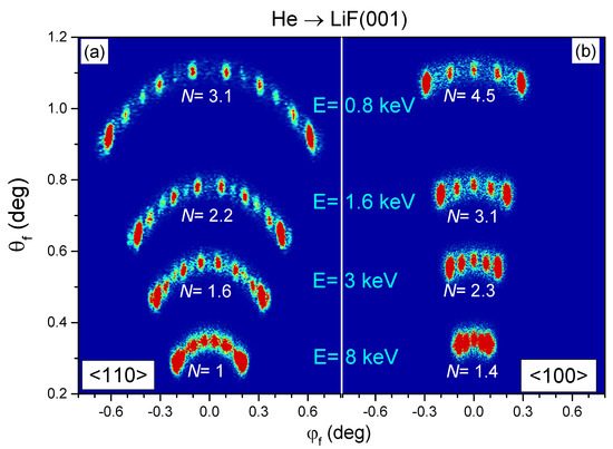
Figure 2.
(Color online) Two-dimensional projectile distributions, as a function of and , for He atoms impinging on LiF(001) along the (a) and (b) directions, with eV. The helium beam is collimated by means of a square aperture with mm. In both panels, angular distributions for different impact energies— , , 3, and 8 keV—are shown, indicating the corresponding N values, as given by Equation (12).
Since for a given collimating setup, N varies not only with the impact energy, but also with the channel width, as given by Equation (12), the different general behavior of the angular distributions of Figure 2a,b will be discussed in terms of the incidence channel in the next Subsection. However, before proceeding further, it is convenient to remember that the structures of GIFAD spectra come from the combination of inter- and intra-channel interferences, each of them being associated with a different factor of the SIVR transition amplitude [32]: The inter-channel factor, produced by interference among parallel channels, which gives rise to periodic Bragg peaks, and the intra-channel factor, due to interference inside a single channel, which acts as an enveloped function that displays supernumerary rainbow maxima [33,44]. Accordingly, for extended coherent illuminations, covering several parallel channels, GIFAD spectra present Bragg peaks modulated by the intra-channel interference. But for the Bragg structures disappear, causing only supernumerary maxima, corresponding to pure intra-channel interference, to be visible in the projectile distribution. Therefore, it is evident that the number N of coherently illuminated channels is a crucial parameter that determines the general shape of GIFAD patterns.
3.2. Influence of the Incidence Channel
In Figure 2a, corresponding to the direction, the application of Equation (12) for the lowest energy— keV—leads to parallel channels coherently illuminated by the He beam. As a result, the projectile distribution displays well separated Bragg peaks, whose intensities are determined by the intra-channel factor which acts as a form factor [29]. However, when E augments, and consequently, N decreases, these Bragg maxima broaden [32], causing the interference structures for keV to become comparatively wider than those for keV. In Figure 2a the Bragg peaks for incidence start to blur out for a total energy about 3 keV, for which , while the limit case corresponding to pure intra-channel interference is reached at keV. At this energy, a single channel is coherently illuminated by the incident beam, producing a projectile distribution with supernumerary maxima only. In contrast with this strong dependence on E of the patterns, in Figure 2b, for the same impact energies as in Figure 2a but along , all the spectra display a constant number of Bragg peaks (i.e., 5 peaks). This is in accord with N values higher than 1, varying from to for the lowest and highest energies, respectively, as indicated in Figure 2b.
To investigate thoroughly the energy dependence of the projectile distributions displayed in Figure 2, in Figure 3 we plot the corresponding SIVR differential probabilities as a function of the deflection angle (see Figure 1). Under ideal scattering conditions, involving the incidence of transversely extended wave packets, these -distributions were expected to be independent of E at the same [29]. Nevertheless, in concordance with Figure 2a, we remarkably found that the spectra of Figure 3a are severely affected by E if the same collimating setup is used for all the energies. In Figure 3a, for incidence with keV [] the projectile distribution as a function of the deflection angle displays well-defined Bragg peaks, placed at the angular positions (indicated with vertical dashed lines) satisfying , where m is an integer number. But these Bragg structures progressively fade out as the energy increases, bringing to light supernumerary rainbows, as observed for keV [] at the top of Figure 3a. Instead, for incidence, the spectra of Figure 3b shows well-resolved Bragg maxima for most of the energies and the structures start to blur out only for the highest impact energy, keV, corresponding to . In addition, all the spectra of Figure 3 show high-intensity rainbow maxima at the outermost angles, which have a classical origin [39,45].
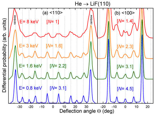
Figure 3.
(Color online) Angular spectra, as a function of the deflection angle , for the cases considered in Figure 2. Dashed vertical lines indicate the angular positions of Bragg peaks.
3.3. Influence of the Projectile Mass
To study the influence of the projectile mass on the coherence of the atomic beam, we consider Ne instead of He projectiles. The angular distributions of neon atoms scattered along the channel, plotted in Figure 4, display a behavior analogous to that shown in Figure 3a for helium. However, for Ne projectiles the dependence of N on the atomic mass, as given by Equation (12), originates a reduction of the number of coherently illuminated channels in comparison with He at the same impact energy. Therefore, under the same collimating conditions, the limit energy for the observation of inter-channel interference in Ne spectra results to be about 5 times lower than in the case of He impact. Hence, in Figure 4 the Ne distribution for keV shows only supernumerary rainbow maxima, which contrasts with the Bragg structures of Figure 3a for the same impact energy of He projectiles. Notice that in Figure 4 well-resolved Bragg peaks are only present in the Ne distribution for keV [], which is comparable to that for keV He projectiles in Figure 3a, indicating the reduced energy window where inter-channel interferences can be observed for Ne impact. These results suggest that the transverse coherence length might be the central parameter that limits the observation of Bragg peaks in experimental Ne spectra, rather than the thermal vibrations of the surface atoms or the spatial resolution of the detector, as it was previously considered [34].
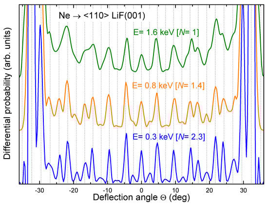
Figure 4.
(Color online) Analogous to Figure 3 for Ne atoms impinging on LiF(001) along the direction, with eV and total energies , , and keV.
4. Dependence on the Shape of the Collimating Slit: Square versus Circular
In this Section we analyze the influence of the geometrical shape of the collimating opening on GIFAD patterns by contrasting results for the He/LiF(001) system derived by using square and circular collimating slits, respectively. In Figure 5 we display two-dimensional projectile distributions, as a function of and , for He incidence along the direction with eV and two different total energies: and 8 keV. As given by Equation (8), the transverse coherence length of the impinging wave packet along the -direction does not depend on the opening shape if it is expressed as a function of d. Thence, the number of parallel channels that become totally (for a square aperture) or partially (for a circular aperture) illuminated in a coherent way is similar for both geometries [Equation (12)]. This behavior is confirmed by the GIFAD patterns of Figure 5a, which display inter-channel interference structures, as well as by the ones of Figure 5b, which present supernumerary rainbows only, both being weakly affected by the collimating shape.

Figure 5.
(Color online) Two-dimensional distribution, as a function of and , for He atoms impinging along with eV and total energy: (a) keV and (b) keV. Square and circular collimating openings, with mm, are considered in the left and right panels, respectively.
Again, the influence of the shape of the collimating slit can be exhaustively examined by comparing differential probabilities, as a function of the deflection angle , as shown in Figure 6. In Figure 6a,b, for and 8 keV, respectively, the spectra corresponding to square and circular collimations look alike. Only the intensities of the peaks are higher for the square collimation than for the circular one, this fact being related to the averaged transverse length of the surface area coherently illuminated by the incident beam, which is longer for the square than for the circular aperture. Moreover, despite the difference between and [Equation (10)], in Figure 6 the widths of the interference maxima corresponding to the distributions for square and circular openings are similar, indicating a slight dependence on the azimuthal width of the initial momentum wave packet.
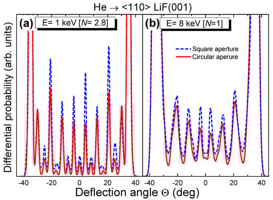
Figure 6.
(Color online) Differential probabilities, as a function of the deflection angle , for the cases of Figure 5. Red solid (blue dashed) line, differential probability for the circular (square) collimating opening.
In addition, it should be noticed that the use of any other collimating scheme, different from the ones considered in this work, might affect present results, requiring the generalization of the Appendix A for the specific experimental collimation condition.
5. Contribution of the Spot-Beam Effect
Finally, we address the spot-beam contribution, which is produced by the different relative positions of the focus point of the projectiles. Regarding focusing effects, it is important to mention that all the results presented in the previous Sections were obtained from coherently illuminated regions with a transverse length longer than or equal to the channel width, that is, with . Under such a constraint, the SIVR transition amplitudes given by Equation (1) are nearly independent of , which makes it possible to approximate
where corresponds to a focus position in the middle of the incidence channel.
However, the spot-beam effect starts to be relevant when E increases, under a fixed collimating condition, causing the coherently lighted area to cover a transverse length smaller than the channel width (i.e., ). In this case, different positions give rise to different amplitudes , which provide information of local zones of the atom-surface potential inside a single channel. In a simplified picture, each atom probes the region of the effective equipotential contour (i.e., averaged along the axial channel) that is around the turning point of its classical trajectory, with being approximately the transverse length of the explored zone [19]. Thence, for values about or lower than the half of the channel width, the partial distributions present interference structures placed at negative or positive deflection angles, depending on the slope of the averaged equipotential contour in the probed zone. Only when these partial contributions are added, as given by Equation (11), the angular spectrum including the spot-beam contribution presents supernumerary peaks symmetrically distributed with respect to the specular direction. However, in this case the spot-beam effect also introduces a non-coherent background, which reduces the visibility of the interference structures, in comparison with that of the spectrum for .
To exemplify the above-mentioned fact, in Figure 7 we analyze the angular distribution of Ne atoms scattered along the direction with eV and the total energy keV (i.e., ). Like in Section 3, a square collimating slit, with mm, is used to collimate the atomic beam. In Figure 7a the differential probability including the spot-beam contribution [Equation (11)] is contrasted with the pure intra-channel spectrum, evaluated from Equation (13) with , as a function of the deflection angle. Figure 7a shows how the spot-beam effect, by means of the addition of different -contributions, helps to recover supernumerary maxima along the whole -range. However, in addition, the spot-beam effect originates a non-coherent background, centered at , which modifies the relative intensities of the interference structures, affecting their visibility.
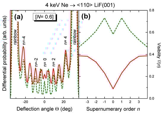
Figure 7.
(Color online) For Ne atoms impinging along with eV and keV : (a) Angular spectra, as a function of the deflection angle ; (b) visibility , as a function of the supernumerary order n. In both panels, red solid line, results including the spot-beam effect [Equation (11)]; dark-green dashed line, pure intra-channel distribution corresponding to [Equation (13)].
The visibility , associated with the supernumerary maximum labelled with n in Figure 7a, with , can be defined as [19,38]
where is the differential probability , derived from Equation (11), at the n-supernumerary maximum [46], and denotes the averaged value of the differential probability at the positions of the two adjacent minima. In Figure 7b we compare , including the spot-beam effect, with the visibility corresponding to the pure intra-channel spectrum, as a function of n, for the case of Figure 7a.
From Figure 7b it is observed that the decreasing of due to the spot-beam contribution is more pronounced for the central maximum than for the outer ones. To understand this behavior, it is necessary to take into account that the intra-channel interference structures are mainly produced by trajectories reflecting at different transverse positions inside the channel, but with the same slope of the averaged equipotential curve. Then, the condition to observe a given supernumerary maximum in the projectile distribution is given by , where is the transverse distance between the turning points of the corresponding interfering trajectories. Since for scattering from LiF(001) the maximum -value, that is, , corresponds to the central peak of the intra-channel spectrum, the visibility of the central maximum, , is more affected as decreases, becoming lower than the channel width.
For higher E (lower N) values, the visibilities of the supernumerary peaks substantially decrease, in comparison with the ones corresponding to the pure intra-channel spectrum, as illustrated in Figure 8b for keV []. Consequently, the interference structures gradually disappear, and the projectile distribution approximates the classical limit, where for all n-values, causing only pronounced rainbow maxima to be visible, as it is shown in Figure 8a. Concerning decoherence, we should mention that there are other effects not included in our model, like inelastic processes [47], which can contribute to deteriorate the coherence, helping to the transition from quantum to classical projectile distributions.
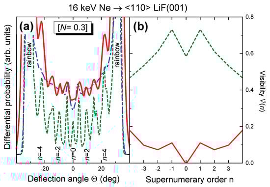
Figure 8.
(Color online) Analogous to Figure 7 for keV . Blue dot-dashed line, classical projectile distribution for .
6. Conclusions
We have analyzed the influence of the total energy, the incidence channel, and the projectile mass on the general characteristics of GIFAD patterns produced by an atomic beam that collides grazingly on a LiF(001) surface, after passing through a fixed collimating setup. We have shown that, even using the same collimating aperture, it is possible to obtain final projectile distributions containing different interference structures by varying the total energy, while keeping the normal energy as a constant. This behavior can be explained in terms of the number N of equivalent parallel channels that are coherently illuminated by the atomic beam.
The N value, derived from the complex degree of coherence of the beam, depends on both the collimating scheme and the incidence conditions. We have shown that when the total energy increases, the decreasing of N modifies the overall features of the GIFAD spectra, which switch gradually from inter-channel patterns to the pure intra-channel distributions. We also investigate the influence of the geometry of the collimating aperture, which was found to play a secondary role.
Additionally, we have studied the spot-beam effect related to the different positions within the crystal lattice of the focus point of the beam. Such a spot-beam contribution becomes relevant when just a portion of a single crystallographic channel is coherently illuminated by the impinging particles. In this case, the spot-beam contribution affects the visibility of the supernumerary maxima, causing for small N values the projectile distributions approximate to the classical ones, with two peaks associated with classical rainbow scattering at the outermost angles.
Finally, notice that the predicted dependence of GIFAD patterns on the transverse coherence length of the projectiles has been successfully contrasted with experimental data in Refs. [16,19]. However, extensive experimental research on the topic should be desirable.
In conclusion, the coherence-length effects are relevant to adequately use GIFAD spectra as a surface analysis tool, as well as to choose the appropriate collimating scheme for the observation of interference effects in a given collision system. Present results might be also a guide for further studies on coherence in other collision systems.
Author Contributions
Investigation, M.S.G., J.E.M., L.F.; Software, M.S.G.; Writing, M.S.G.
Funding
This work was carried out with financial support from CONICET (PIP 2014-2016 GI-386), UBA (UBACYT 20020170100727BA) and ANPCyT (PICT 2014-2363) of Argentina.
Conflicts of Interest
The authors declare no conflict of interest.
Appendix A. Complex Degree of Coherence for an Atomic Beam Passing through a Circular Collimating Aperture
In this Appendix the Van Cittert-Zernike theorem [38] is applied to evaluate the complex degree of coherence between two points— and —placed on a plane parallel to the crystal surface at a distance , which is illuminated by an extended incoherent quasi-monochromatic source, after passing through a circular collimating opening. Let us consider that both, the extended particle emitter and the collimating aperture, present a circular shape, with diameters e and d (areas and ) respectively. By extending the Van Cittert-Zernike theorem [38] for the case under study, the mutual coherence function reads
where is the intensity of the extended source, assumed as uniform, is the wave number of the atomic beam, and the distances and are indicated in Figure A1 for .
To derive the profile of the incident wave packet it is convenient to choose as the center of the wave packet and , with the and versors laying on the upon-surface plane and parallel to the incidence channel. By assuming, as usually, that the distances and between the source and the collimator and between the collimating slit and the upon-surface plane, respectively, are larger than e, d, and , the mutual intensity function (excluding a normalization factor) can be expressed as:
where
for , and for , with being the Bessel function of order n, , and . In Equation (A2) the parameter is defined by Equation (5) and , with .

Figure A1.
Depiction of the collimating scheme considered in the Appendix, together with the involved coordinates.
Figure A1.
Depiction of the collimating scheme considered in the Appendix, together with the involved coordinates.

The calculation of the mutual intensity function from Equation (A2) requires the numerical evaluation of a two-dimensional integral. However, like in the case of a square opening [17], under the condition of extended source [46], for small values the square modulus of the complex degree of coherence can be roughly described as
where is the spherical Bessel function of order zero.
References
- Moix, J.M.; Pollak, E. Heavy atom quantum diffraction by scattering from surfaces. J. Chem. Phys. 2011, 134, 011103. [Google Scholar] [CrossRef] [PubMed]
- Minniti, M.; Díaz, C.; Cuñado, J.L.F.; Politano, A.; Maccariello, D.; Martín, F.; Farías, D.; Miranda, R. Helium, neon and argon diffraction from Ru(0001). J. Phys. Condens. Matter 2012, 24, 354002. [Google Scholar] [CrossRef] [PubMed]
- Seifert, J.; Lienemann, J.; Schüller, A.; Winter, H. Studies on coherence and decoherence in Fast Atom Diffraction. Nucl. Instrum. Methods Phys. Res. B 2015, 350, 99–105. [Google Scholar] [CrossRef]
- Egodapitiya, K.N.; Sharma, S.; Hasan, A.; Laforge, A.C.; Madison, D.H.; Moshammer, R.; Schulz, M. Manipulating Atomic Fragmentation Processes by Controlling the Projectile Coherence. Phys. Rev. Lett. 2011, 106, 153202. [Google Scholar] [CrossRef] [PubMed]
- Wang, X.; Schneider, K.; LaForge, A.; Kelkar, A.; Grieser, M.; Moshammer, R.; Ullrich, J.; Schulz, M.; Fischer, D. Projectile coherence effects in single ionization of helium. J. Phys. B 2012, 45, 211001. [Google Scholar] [CrossRef]
- Arthanayaka, T.; Lamichhane, B.R.; Hasan, A.; Gurung, S.; Remolina, J.; Borbély, S.; Járai-Szabó, F.; Nagy, L.; Schulz, M. Fully differential study of wave packet scattering in ionization of helium by proton impact. J. Phys. B 2016, 49, 13LT02. [Google Scholar] [CrossRef]
- Karlovets, D.V.; Kotkin, G.L.; Serbo, V.G. Scattering of wave packets on atoms in the Born approximation. Phys. Rev. A 2015, 92, 052703. [Google Scholar] [CrossRef]
- Gassert, H.; Chuluunbaatar, O.; Waitz, M.; Trinter, F.; Kim, H.K.; Bauer, T.; Laucke, A.; Müller, C.; Voigtsberger, J.; Weller, M.; et al. Agreement of Experiment and Theory on the Single Ionization of Helium by Fast Proton Impact. Phys. Rev. Lett. 2016, 116, 073201. [Google Scholar] [CrossRef] [PubMed]
- Sarkadi, L.; Fabre, I.; Navarrete, F.; Barrachina, R.O. Loss of wave-packet coherence in ion-atom collisions. Phys. Rev. A 2016, 93, 032702. [Google Scholar] [CrossRef]
- Navarrete, F.; Ciappina, M.; Sarkadi, L.; Barrachina, R. The role of the wave packet coherence on the ionization cross section of He by p+ and C6+ projectiles. Nucl. Instrum. Methods Phys. Res. B 2017, 408, 165–168. [Google Scholar] [CrossRef]
- Nagy, L.; Járai-Szabó, F.; Borbély, S. The effect of projectile wave packet width on the fully differential ionization cross-sections. J. Phys. B 2018, 51, 144005. [Google Scholar] [CrossRef]
- Schüller, A.; Wethekam, S.; Winter, H. Diffraction of Fast Atomic Projectiles during Grazing Scattering from a LiF(001) Surface. Phys. Rev. Lett. 2007, 98, 016103. [Google Scholar] [CrossRef] [PubMed]
- Rousseau, P.; Khemliche, H.; Borisov, A.G.; Roncin, P. Quantum Scattering of Fast Atoms and Molecules on Surfaces. Phys. Rev. Lett. 2007, 98, 016104. [Google Scholar] [CrossRef] [PubMed]
- Lienemann, J.; Schüller, A.; Blauth, D.; Seifert, J.; Wethekam, S.; Busch, M.; Maass, K.; Winter, H. Coherence during Scattering of Fast H Atoms from a LiF(001) Surface. Phys. Rev. Lett. 2011, 106, 067602. [Google Scholar] [CrossRef] [PubMed]
- Busch, M.; Lienemann, J.; Seifert, J.; Schüller, A.; Winter, H. Decoherence in grazing scattering of fast H and He atoms from a LiF(001) surface. Vacuum 2012, 86, 1618–1623. [Google Scholar] [CrossRef]
- Gravielle, M.S.; Miraglia, J.E. Influence of beam collimation on fast-atom diffraction studied via a semiquantum approach. Phys. Rev. A 2015, 92, 062709. [Google Scholar] [CrossRef]
- Gravielle, M.S.; Miraglia, J.E. Single- and double-slit collimating effects on fast-atom diffraction spectra. Nucl. Instrum. Methods Phys. Res. B 2016, 382, 42–48. [Google Scholar] [CrossRef]
- Gravielle, M.S. Fast interaction of atoms with crystal surfaces: coherent lighting. J. Phys. Conf. Ser. 2017, 875, 012006. [Google Scholar] [CrossRef]
- Frisco, L.; Miraglia, J.E.; Gravielle, M.S. Spot-beam effect in grazing atom-surface collisions: From quantum to classical. J. Phys. Condens. Matter 2018, 30, 405001. [Google Scholar] [CrossRef] [PubMed]
- Schüller, A.; Wethekam, S.; Blauth, D.; Winter, H.; Aigner, F.; Simonović, N.; Solleder, B.; Burgdörfer, J.; Wirtz, L. Rumpling of LiF(001) surface from fast atom diffraction. Phys. Rev. A 2010, 82, 062902. [Google Scholar] [CrossRef]
- Atkinson, P.; Eddrief, M.; Etgens, V.; Khemliche, H.; Debiossac, M.; Momeni, A.; Mulier, M.; Lalmi, B.; Roncin, P. Dynamic grazing incidence fast atom diffraction during molecular beam epitaxial growth of GaAs. Appl. Phys. Lett. 2014, 105, 021602. [Google Scholar] [CrossRef]
- Rubiano, C.A.R.; Bocan, G.A.; Gravielle, M.S.; Bundaleski, N.; Khemliche, H.; Roncin, P. Ab initio potential for the He-Ag(110) interaction investigated using grazing-incidence fast-atom diffraction. Phys. Rev. A 2013, 87, 012903. [Google Scholar] [CrossRef]
- Seifert, J.; Winter, H. Quantitative structure determination using grazing scattering of fast atoms: Oxygen-induced missing-row reconstruction of Mo(112). Phys. Rev. B 2016, 93, 205417. [Google Scholar] [CrossRef]
- Debiossac, M.; Zugarramurdi, A.; Mu, Z.; Lunca-Popa, P.; Mayne, A.J.; Roncin, P. Helium diffraction on SiC grown graphene: Qualitative and quantitative descriptions with the hard-corrugated-wall model. Phys. Rev. B 2016, 94, 205403. [Google Scholar] [CrossRef]
- Seifert, J.; Busch, M.; Meyer, E.; Winter, H. Surface structure of alanine on Cu(110) via grazing scattering of fast atoms and molecules. Phys. Rev. B 2014, 89, 075404. [Google Scholar] [CrossRef]
- Momeni, A.; Casagrande, E.M.S.; Dechaux, A.; Khemliche, H. Ultrafast Crystallization Dynamics at an Organic-Inorganic Interface Revealed in Real Time by Grazing Incidence Fast Atom Diffraction. J. Phys. Chem. Lett. 2018, 9, 908–913. [Google Scholar] [CrossRef] [PubMed]
- Schüller, A.; Blauth, D.; Seifert, J.; Busch, M.; Winter, H.; Gärtner, K.; Włodarczyk, R.; Sauer, J.; Sierka, M. Fast atom diffraction during grazing scattering from a MgO(001) surface. Surf. Sci. 2012, 606, 161–173. [Google Scholar] [CrossRef]
- Schüller, A.; Busch, M.; Seifert, J.; Wethekam, S.; Winter, H.; Gärtner, K. Superstructures of oxygen and sulphur on a Fe(110) surface via fast atom diffraction. Phys. Rev. B 2009, 79, 235425. [Google Scholar] [CrossRef]
- Schüller, A.; Winter, H.; Gravielle, M.S.; Pruneda, J.M.; Miraglia, J.E. He-LiF surface interaction potential from fast atom diffraction. Phys. Rev. A 2009, 80, 062903. [Google Scholar] [CrossRef]
- Zugarramurdi, A.; Debiossac, M.; Lunca-Popa, P.; Mayne, A.J.; Momeni, A.; Borisov, A.G.; Mu, Z.; Roncin, P.; Khemliche, H. Determination of the geometric corrugation of graphene on SiC(0001) by grazing incidence fast atom diffraction. Appl. Phys. Lett. 2015, 106, 101902. [Google Scholar] [CrossRef]
- Debiossac, M.; Roncin, P. Image processing for grazing incidence fast atom diffraction. Nucl. Instrum. Methods Phys. Res. B 2016, 382, 36–41. [Google Scholar] [CrossRef]
- Gravielle, M.S.; Miraglia, J.E. Semiquantum approach for fast atom diffraction: Solving the rainbow divergence. Phys. Rev. A 2014, 90, 052718. [Google Scholar] [CrossRef]
- Winter, H.; Schüller, A. Fast atom diffraction during grazing scattering from surfaces. Prog. Surf. Sci. 2011, 86, 169–221. [Google Scholar] [CrossRef]
- Gravielle, M.S.; Schüller, A.; Winter, H.; Miraglia, J. Fast atom diffraction for grazing scattering of Ne atoms from a LiF(001) surface. Nucl. Instrum. Methods Phys. Res. B 2011, 269, 1208–1211. [Google Scholar] [CrossRef]
- Bocan, G.A.; Fuhr, J.D.; Gravielle, M.S. van der Waals effects on grazing-incidence fast-atom diffraction for H on LiF(001). Phys. Rev. A 2016, 94, 022711. [Google Scholar] [CrossRef]
- Miraglia, J.E.; Gravielle, M.S. Reexamination of the interaction of atoms with a LiF(001) surface. Phys. Rev. A 2017, 95, 022710. [Google Scholar] [CrossRef]
- Bocan, G.A.; Gravielle, M.S. GIFAD for He/KCl(001). Structure in the pattern for ⟨110⟩ incidence as a measure of the projectile-cation interaction. Nucl. Instrum. Methods Phys. Res. B 2018, 421, 1–6. [Google Scholar] [CrossRef]
- Born, M.; Wolf, E. Principles of Optics; Pergamon Press: Oxford, UK, 1986; Chapter 10. [Google Scholar]
- Guantes, R.; Sanz, A.S.; Margalef-Roig, J.; Miret-Artés, S. Atom-surface diffraction: A trajectory description. Surf. Sci. Rep. 2004, 53, 199–330. [Google Scholar] [CrossRef]
- Schaff, J.F.; Langen, T.; Schmiedmayer, J. Interferometry with atoms. Riv. Nuovo Cimento 2014, 7, 509–589. [Google Scholar]
- Tonomura, A. Electron Holography. Prog. Opt. 1986, 23, 183–220. [Google Scholar]
- Cohen-Tannoudji, C.; Diu, B.; Laloë, F. Quantum Mechanics; Willey-VCH: Paris, France, 2011; Chapter I. [Google Scholar]
- Meyer, F.; Folkerts, L.; Schippers, S. Angular and charge state distributions of highly charged ions scattered during low energy surface-channeling interactions with Au(l10). Nucl. Instrum. Methods Phys. Res. B 1995, 100, 366–372. [Google Scholar] [CrossRef]
- Schüller, A.; Winter, H. Supernumerary Rainbows in the Angular Distribution of Scattered Projectiles for Grazing Collisions of Fast Atoms with a LiF(001) Surface. Phys. Rev. Lett. 2008, 100, 097602. [Google Scholar] [CrossRef] [PubMed]
- Farias, D.; Rieder, K.H. Atomic beam diffraction from solid surfaces. Rep. Prog. Phys. 1998, 61, 1575–1664. [Google Scholar] [CrossRef]
- Notice that the parameter n used to label the different supernumerary maxima does not coincide with the supernumerary rainbow order as defined in Ref. [33].
- Roncin, P.; Debiossac, M. Elastic and inelastic diffraction of fast atoms, Debye-Waller factor, and Mössbauer-Lamb-Dicke regime. Phys. Rev. B 2017, 96, 035415. [Google Scholar] [CrossRef]


© 2018 by the authors. Licensee MDPI, Basel, Switzerland. This article is an open access article distributed under the terms and conditions of the Creative Commons Attribution (CC BY) license (http://creativecommons.org/licenses/by/4.0/).