Induction Motor Drives Fed by an NPC Inverter with Unbalanced DC-Link

 , , , and
Abstract
:1. Introduction
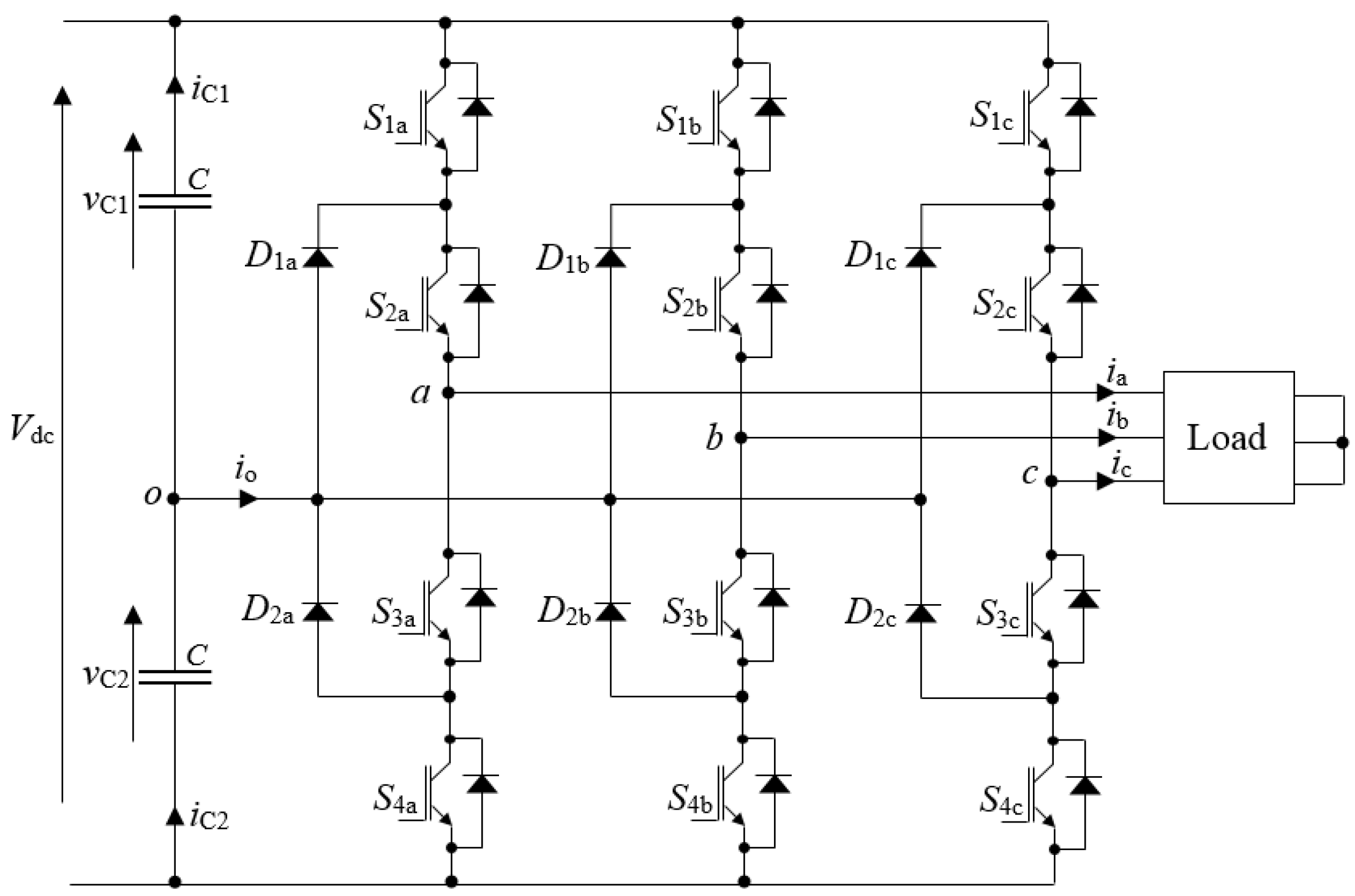
2. Model of the NPC Inverter with Unbalanced DC-Link
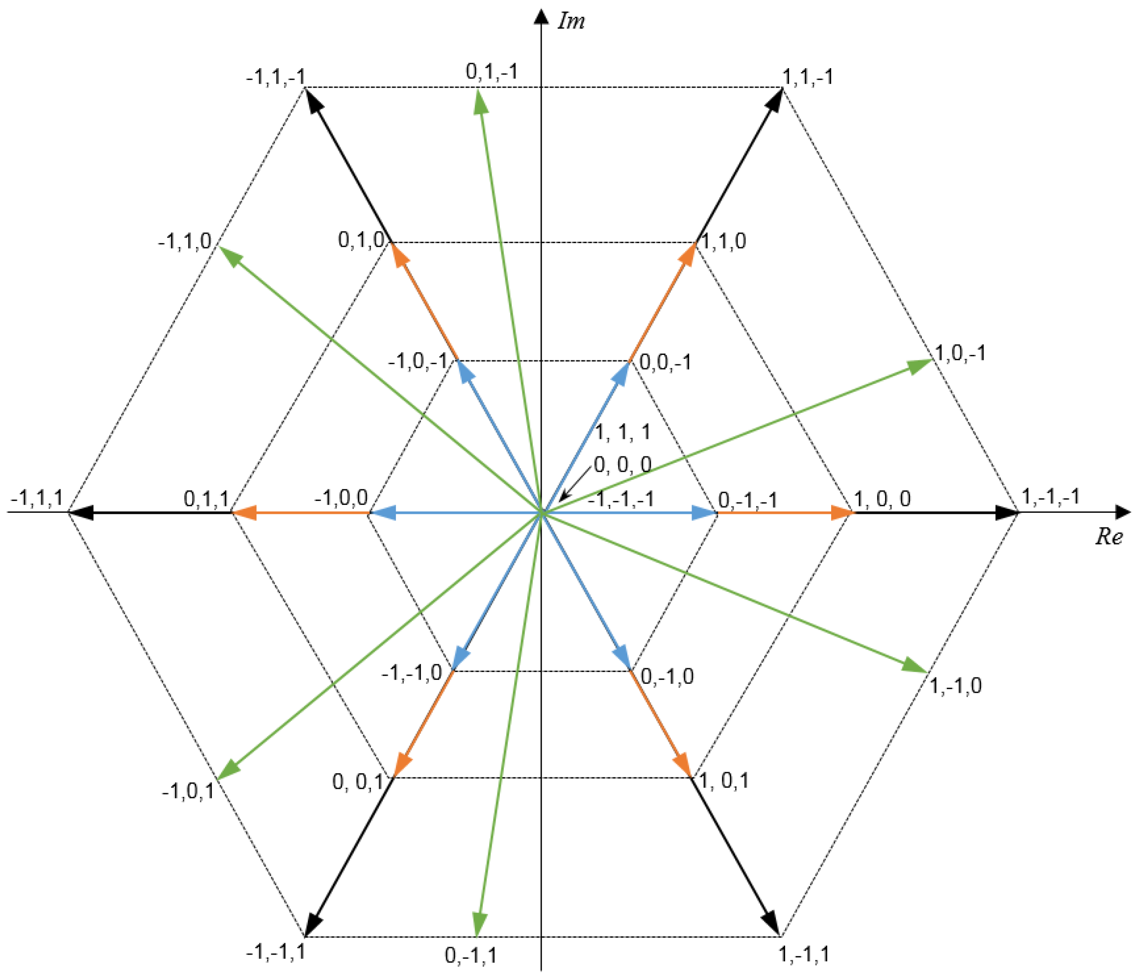
3. SVM with Unbalanced DC-Link
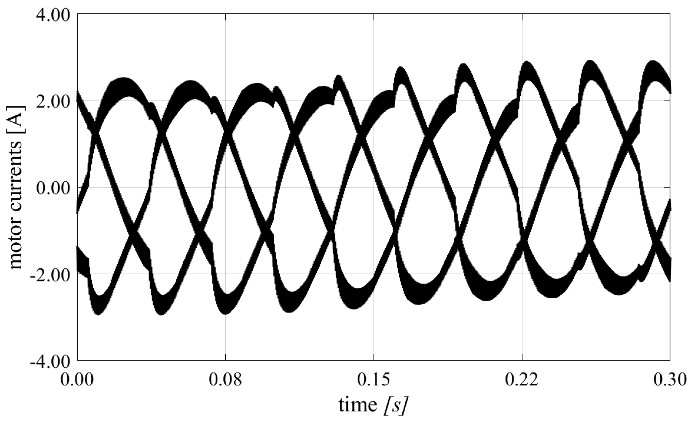
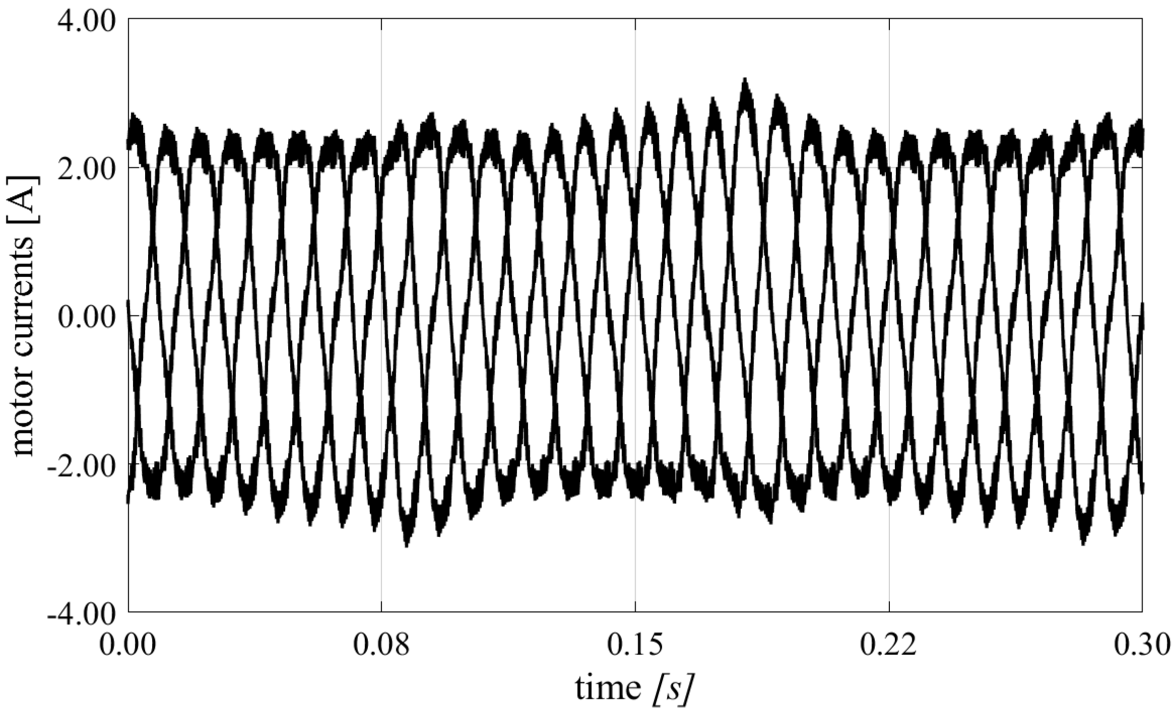
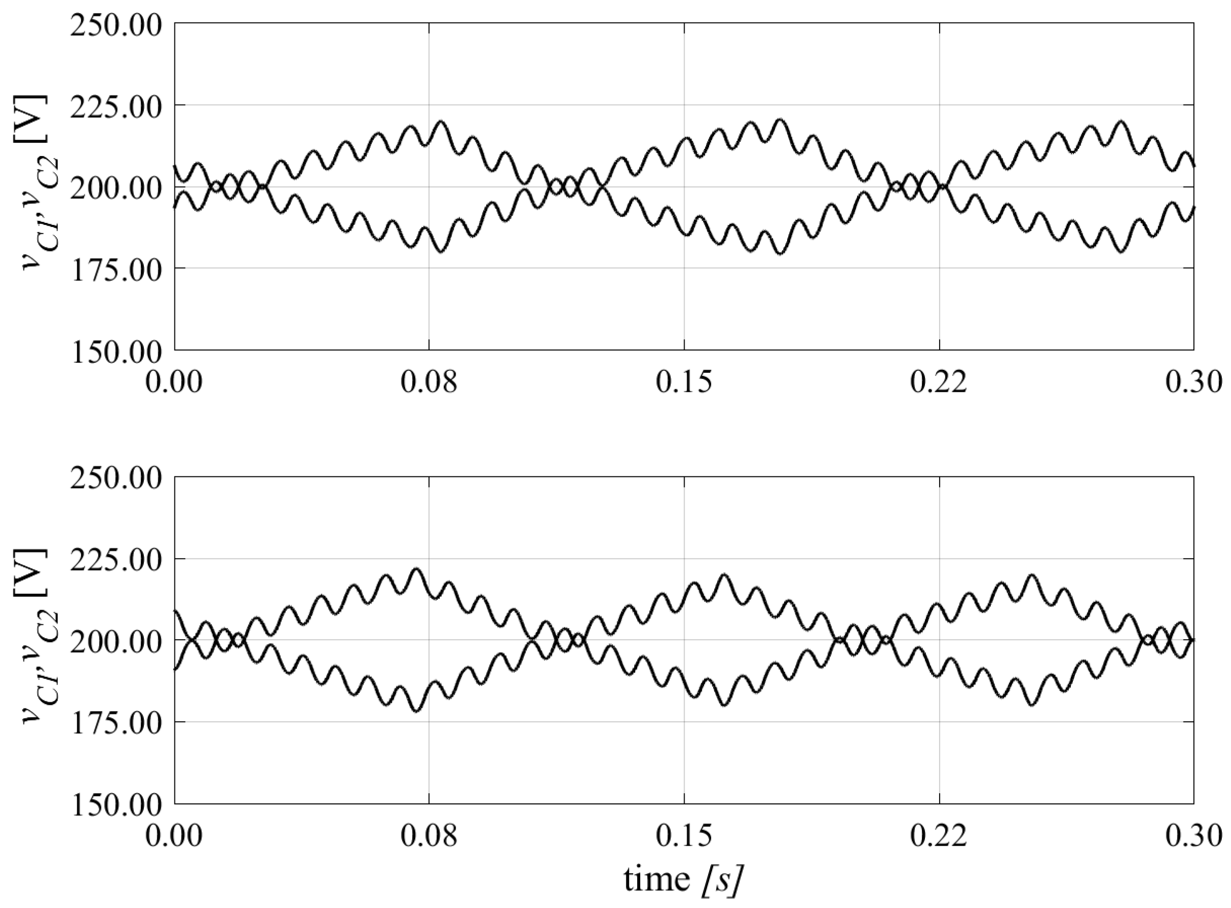
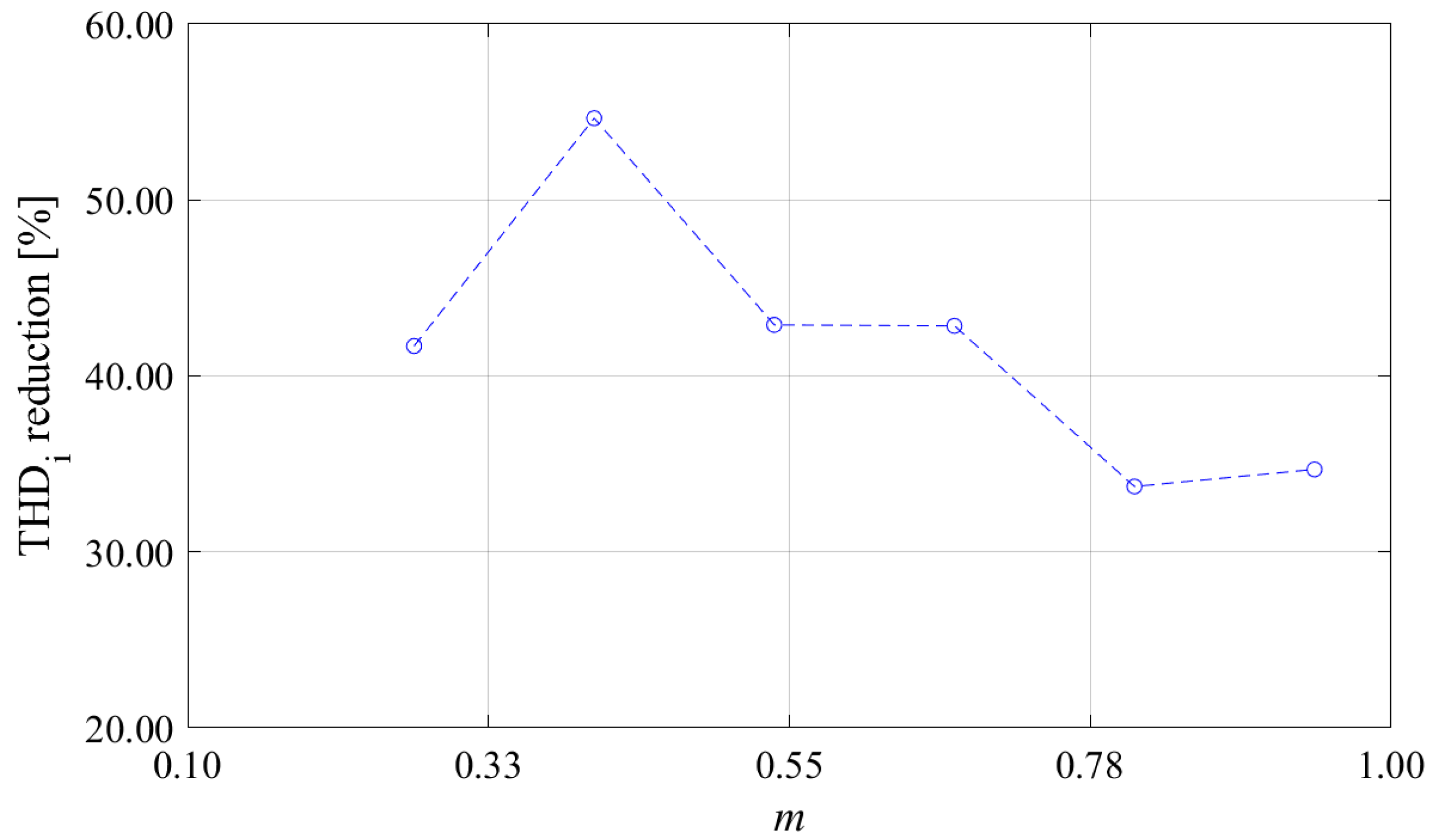
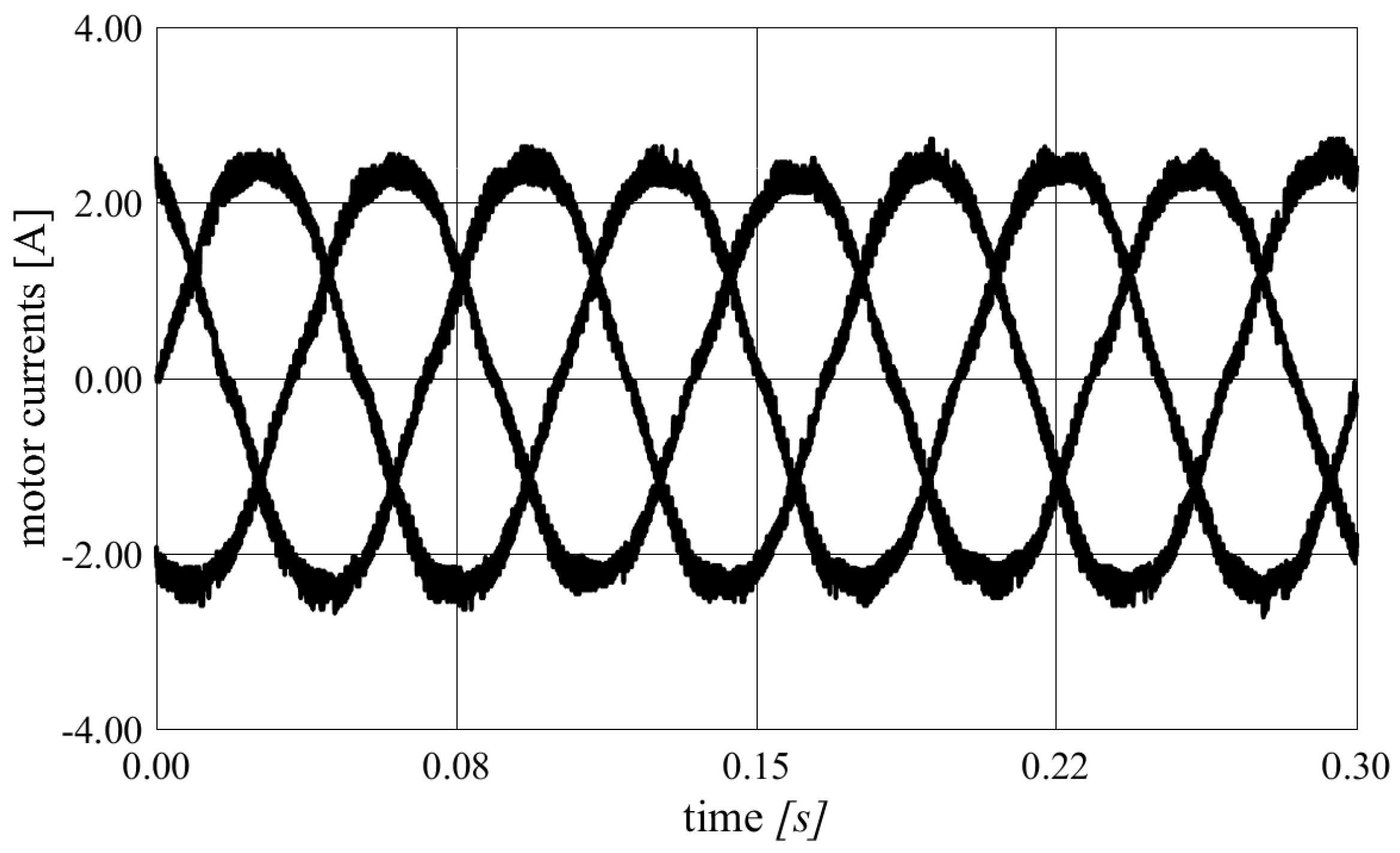
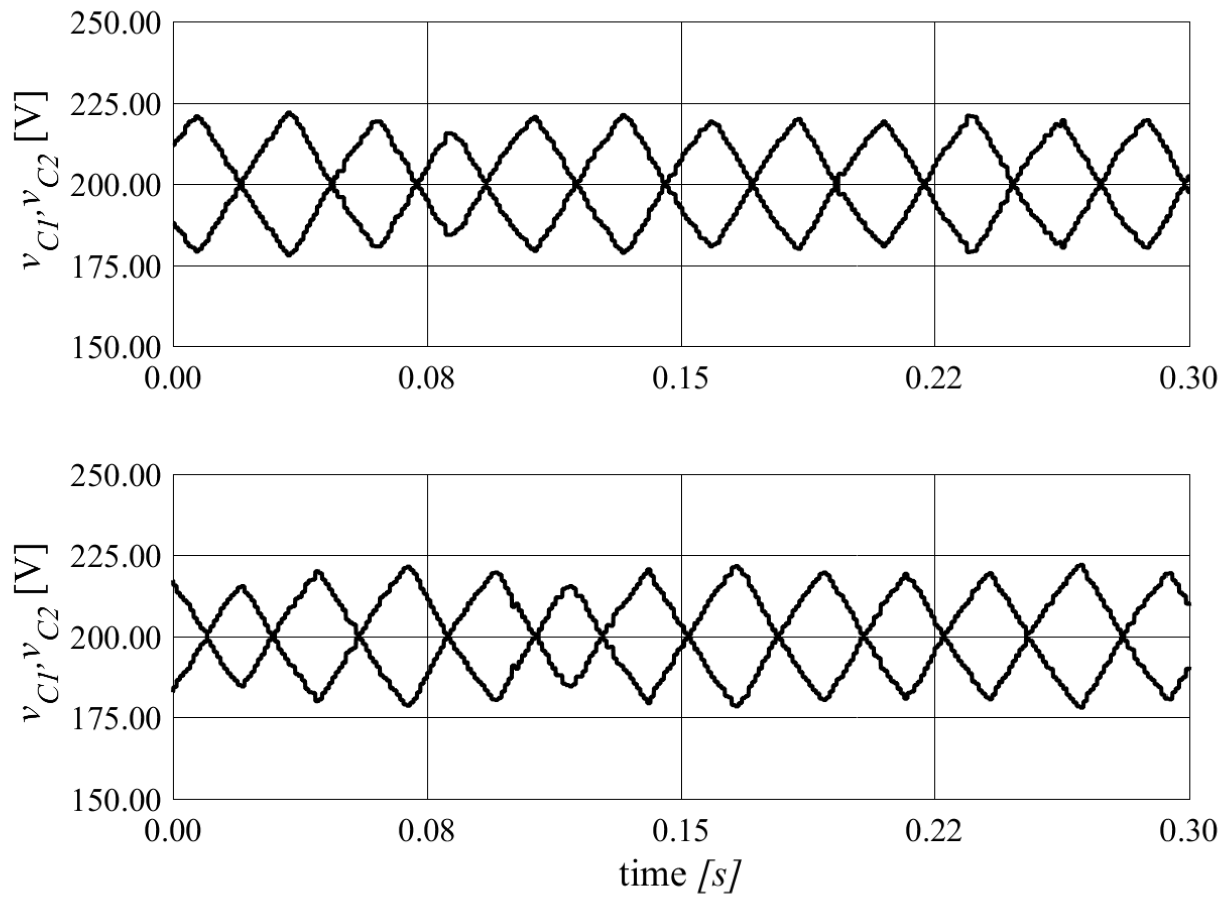
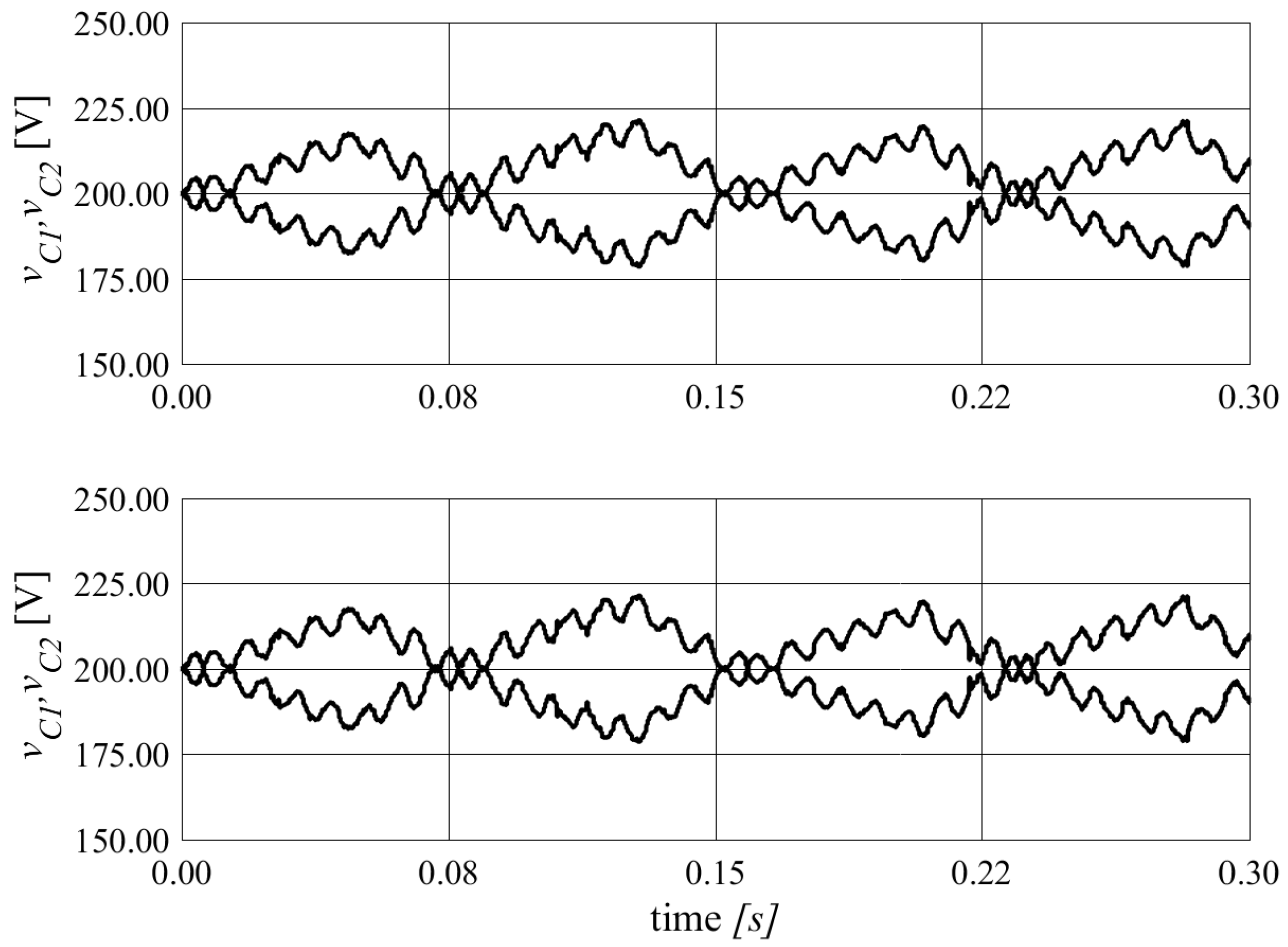
4. Numerical Results
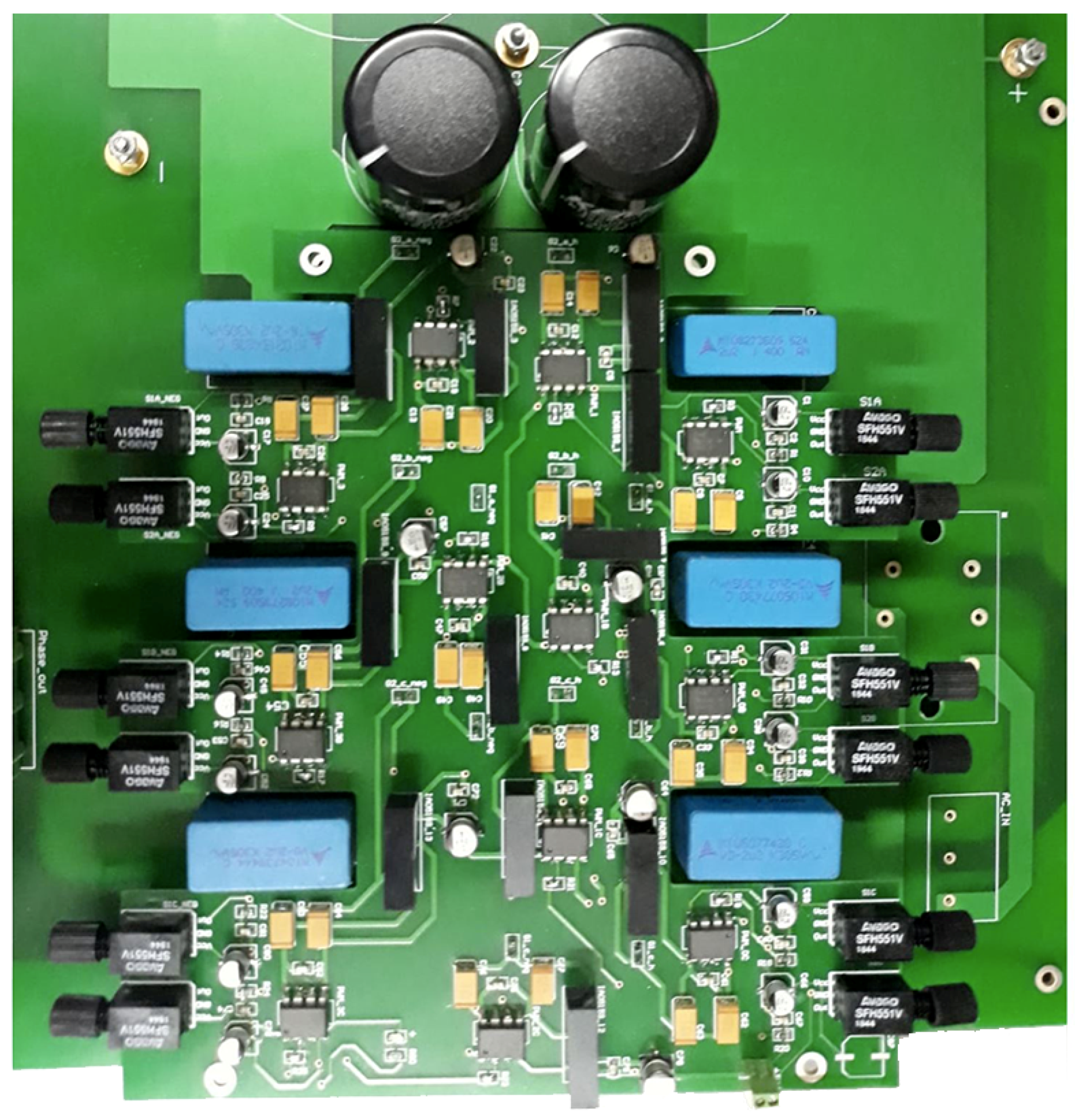
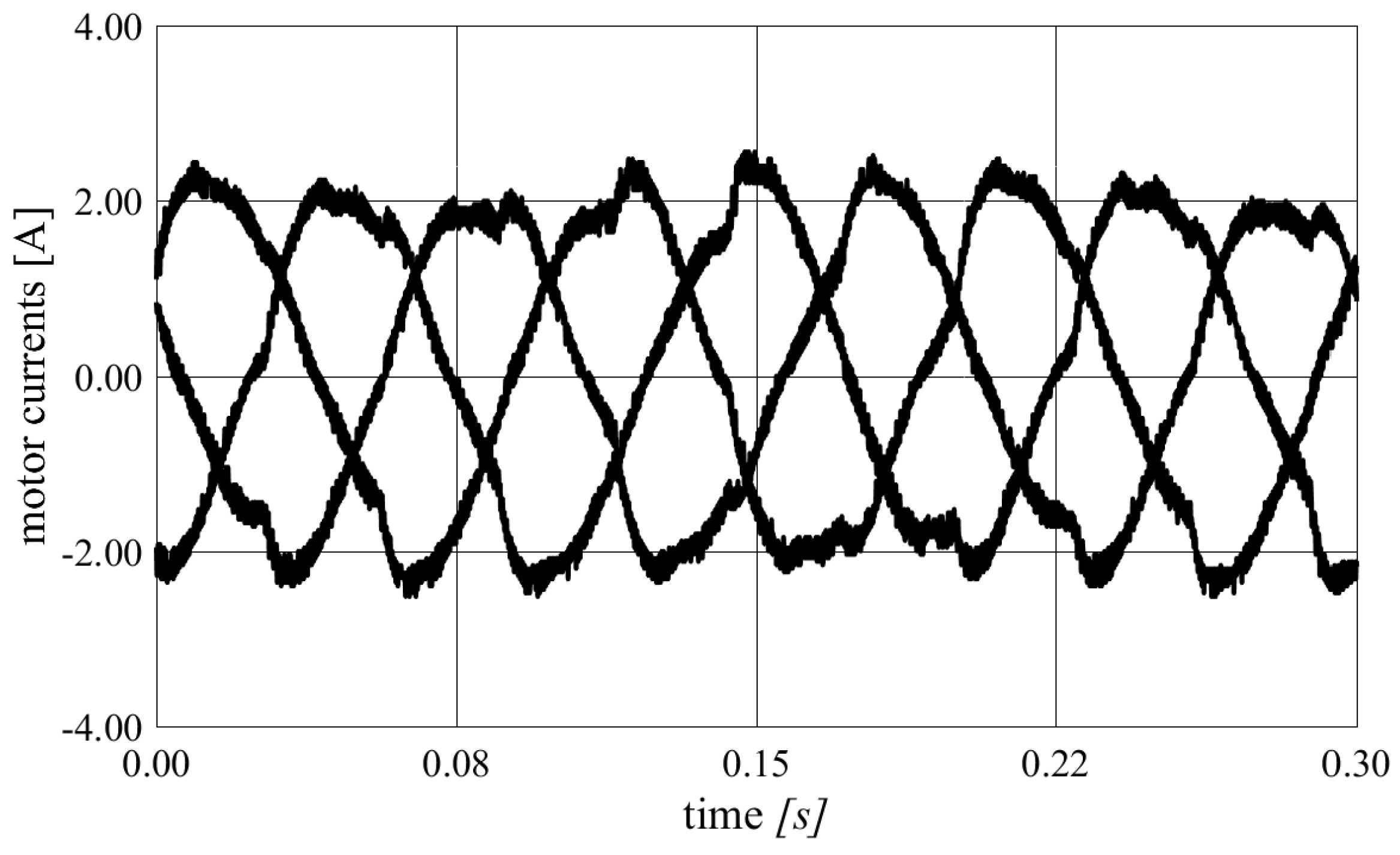
5. Experimental Results
6. Conclusions
Author Contributions
Funding
Conflicts of Interest
References
- Abronzini, U.; Attaianese, C.; D’Arpino, M.; Monaco, M.D.; Tomasso, G. Steady-State Dead-Time Compensation in VSI. IEEE Trans. Ind. Electron. 2016, 63, 5858–5866. [Google Scholar] [CrossRef]
- Attaianese, C.; Monaco, M.D.; Tomasso, G. High Performance Digital Hysteresis Control for Single Source Cascaded Inverters. IEEE Trans. Ind. Inform. 2013, 9, 620–629. [Google Scholar] [CrossRef]
- Attaianese, C.; Monaco, M.D.; Tomasso, G. Power Control for Fuel-Cell-Supercapacitor Traction Drive. IEEE Trans. Veh. Technol. 2012, 61, 1961–1971. [Google Scholar] [CrossRef]
- Nabae, A.; Takahashi, I.; Akagi, H. A new neutral-point-clamped PWM inverter. IEEE Trans. Ind. Appl. 1981, IA-17, 518–523. [Google Scholar] [CrossRef]
- Celanovic, N.; Borojevic, D. A comprehensive study of neutral-point voltage balancing problem in three-level neutral-point-clamped voltage source PWM inverters. In Proceedings of the APEC’99, Fourteenth Annual Applied Power Electronics Conference and Exposition, 1999 Conference Proceedings (Cat. No. 99CH36285), Dallas, TX, USA, 14–18 March 1999; Volume 1, pp. 535–541. [Google Scholar]
- Chen, W.; Sun, H.; Gu, X.; Xia, C. Synchronized space-vector PWM for three-level VSI with lower harmonic distortion and switching frequency. IEEE Trans. Power Electron. 2015, 31, 6428–6441. [Google Scholar] [CrossRef]
- Lyu, J.; Hu, W.; Wu, F.; Yao, K.; Wu, J. Three-level saddle space vector pulse width modulation strategy based on two-level space vector pulse width modulation for neutral-point-clamped three-level inverters. IET Power Electron. 2016, 9, 874–882. [Google Scholar] [CrossRef]
- Jiao, Y.; Lee, F.C.; Lu, S. Space vector modulation for three-level NPC converter with neutral point voltage balance and switching loss reduction. IEEE Trans. Power Electron. 2013, 29, 5579–5591. [Google Scholar] [CrossRef]
- Choudhury, A.; Pillay, P.; Williamson, S.S. Modified DC-Bus Voltage-Balancing Algorithm Based Three-Level Neutral-Point-Clamped IPMSM Drive for Electric Vehicle Applications. IEEE Trans. Ind. Electron. 2016, 63, 761–772. [Google Scholar] [CrossRef]
- Pou, J.; Zaragoza, J.; Ceballos, S.; Saeedifard, M.; Boroyevich, D. A carrier-based PWM strategy with zero-sequence voltage injection for a three-level neutral-point-clamped converter. IEEE Trans. Power Electron. 2010, 27, 642–651. [Google Scholar] [CrossRef]
- Zhang, Y.; Li, J.; Li, X.; Cao, Y.; Sumner, M.; Xia, C. A method for the suppression of fluctuations in the neutral-point potential of a three-level NPC inverter with a capacitor-voltage loop. IEEE Trans. Power Electron. 2016, 32, 825–836. [Google Scholar] [CrossRef]
- Busquets-Monge, S.; Bordonau, J.; Boroyevich, D.; Somavilla, S. The nearest three virtual space vector PWM—A modulation for the comprehensive neutral-point balancing in the three-level NPC inverter. IEEE Power Electron. Lett. 2004, 2, 11–15. [Google Scholar] [CrossRef]
- Celanovic, N.; Boroyevich, D. A fast space-vector modulation algorithm for multilevel three-phase converters. IEEE Trans. Ind. Appl. 2001, 37, 637–641. [Google Scholar] [CrossRef]
- Patrao, I.; Garcera, G.; Figueres, E.; Gonzalez-Medina, R. Grid-tie inverter topology with maximum power extraction from two photovoltaic arrays. IET Renew. Power Gener. 2014, 8, 638–648. [Google Scholar] [CrossRef]
- Andrade, A.S.; da Silva, E.R.C. DC-link control of a three-level NPC inverter fed by shaded photovoltaic system. In Proceedings of the IEEE 13th Brazilian Power Electronics Conference and 1st Southern Power Electronics Conference (COBEP/SPEC), Fortaleza, Brazil, 29 November–2 December 2015. [Google Scholar]
- Pou, J.; Boroyevich, D.; Pindado, R. New feedforward space-vector PWM method to obtain balanced AC output voltages in a three-level neutral-point-clamped converter. IEEE Trans. Ind. Electron. 2002, 49, 1026–1034. [Google Scholar] [CrossRef]
- Wu, X.; Xie, L.; Yin, J.; Ton, Y.; Yang, J. A three-level PV inverter with independent MPPT control for two sets of photovoltaic cells in series connection. Trans. China Electrotech. Soc. 2013, 28, 202–208. [Google Scholar]
- Wu, X.; Tan, G.; Ye, Z.; Yao, G.; Liu, Z.; Liu, G. Virtual-Space-Vector PWM for a Three-Level Neutral-Point-Clamped Inverter with Unbalanced DC-Links. IEEE Trans. Power Electron. 2018, 33, 2630–2642. [Google Scholar] [CrossRef]
- Ye, Z.; Xu, Y.; Wu, X.; Tan, G.; Deng, X.; Wang, Z. A Simplified PWM Strategy for a Neutral-Point-Clamped (NPC) Three-Level Converter with Unbalanced DC Links. IEEE Trans. Power Electron. 2016, 31, 3227–3238. [Google Scholar] [CrossRef]
- Abronzini, U.; Attaianese, C.; Di Monaco, M.; Tomasso, G.; D’Arpino, M. SVM of Three-Level NPC Inverter with Unbalanced DC-Link. In Proceedings of the 2018 IEEE Energy Conversion Congress and Exposition (ECCE), Portland, OR, USA, 23–27 September 2018; pp. 2215–2221. [Google Scholar] [CrossRef]
- Bose, B.K. Power Electronics and AC Drives; Prentice-Hall: Englewood Cliffs, NJ, USA, 1986; 416p. [Google Scholar]


| Switching State | Output Voltage | ||||
|---|---|---|---|---|---|
| 1 | 1 | 0 | 0 | 1 | |
| 0 | 1 | 1 | 0 | 0 | 0 |
| 0 | 0 | 1 | 1 | −1 | |
| 1.1-kW Induction Motor | ||
| Rated power | 1.1 | kW |
| Rated torque | 7.48 | Nm |
| Rated voltage (rms) | 380 | V |
| Rated current (rms) | 2.65 | A |
| Pole pairs | 2 | |
| Stator resistance | 7.5 | mΩ |
| Rotor resistance referred to stator | 4.8 | mΩ |
| Stator leakage inductance | 20 | mH |
| Rotor leakage indutance | 20 | mH |
| Air gap inductance | 430 | mH |
| Three-Level NPC Inverter | ||
| DC-link voltage, | 400 | V |
| modulation period, | 500 | μs |
| DC-link capacitor, C | 330 | μF |
© 2019 by the authors. Licensee MDPI, Basel, Switzerland. This article is an open access article distributed under the terms and conditions of the Creative Commons Attribution (CC BY) license (http://creativecommons.org/licenses/by/4.0/).
Share and Cite
Abronzini, U.; Attaianese, C.; D’Arpino, M.; Di Monaco, M.; Tomasso, G. Induction Motor Drives Fed by an NPC Inverter with Unbalanced DC-Link. Electronics 2019, 8, 1379. https://doi.org/10.3390/electronics8121379
Abronzini U, Attaianese C, D’Arpino M, Di Monaco M, Tomasso G. Induction Motor Drives Fed by an NPC Inverter with Unbalanced DC-Link. Electronics. 2019; 8(12):1379. https://doi.org/10.3390/electronics8121379
Chicago/Turabian StyleAbronzini, Umberto, Ciro Attaianese, Matilde D’Arpino, Mauro Di Monaco, and Giuseppe Tomasso. 2019. "Induction Motor Drives Fed by an NPC Inverter with Unbalanced DC-Link" Electronics 8, no. 12: 1379. https://doi.org/10.3390/electronics8121379
APA StyleAbronzini, U., Attaianese, C., D’Arpino, M., Di Monaco, M., & Tomasso, G. (2019). Induction Motor Drives Fed by an NPC Inverter with Unbalanced DC-Link. Electronics, 8(12), 1379. https://doi.org/10.3390/electronics8121379