Abstract
Currently, the industry is using the MODBUS communication method, utilizing RS485 for the distributed equipment and network construction. This method has a rather good transmission and reception distance but has a disadvantage in that it is a half-duplex communication method that cannot simultaneously transmit and receive. Therefore, there is a great need for a full-duplex communication system that can simultaneously transmit and receive two-wire communications. Therefore, in this paper, we propose new communication hardware equipment that can implement a full-duplex communication method by communication signal level in order to overcome the disadvantage of communication speed when using a full-duplex communication method by time division method. The proposed communication hardware is a structure that can transmit and receive at the same time in such a way that two pieces of equipment communicating by two-wire communication can apply the outgoing signal to the same communication line and detect the received signal at the same time. Therefore, the receiving side can analyze the received signal based on the information on the current transmission signal. This signal can only be analyzed by the two communicating devices, indicating that communication security is very good.
1. Introduction
Recently, in the industrial circles, studies of the smart factory that automates and intellectualizes all manufacturing processes based on Information and Communications Technologies (ICT) have been conducted actively [1,2]. For the automation, the communication between individual devices is essential, and to support this, most of the existing equipment is equipped with a communication port of asynchronous serial communication, such as RS232, RS423, RS422, or RS485. The present industrial circles use the MODBUS communication method using RS485 as a communication method used in network construction with dispersed equipment [3,4,5]. This method is good in terms of the distance between transmission and reception; however, it has the disadvantage of being a half-duplex communication method, which cannot transmit and receive simultaneously [6,7]. To overcome this, various methods are being investigated, and the representative method is a four-wire communication; however, this burdens the wire if the communication line is long. Thus, it is urgently necessary to investigate a full-duplex communication method that can transmit and receive in a two-wire communication [8,9,10]. Thus, this study proposes new hardware equipment for communication which can implement a full-duplex communication method in the level of the communication signal to overcome the disadvantage in communication speed in using a full-duplex communication method by a time-sharing system. The proposed communications hardware is a structure that can transmit and receive simultaneously in a way that can detect the received signal, while at the same time, two pieces of equipment (which communicate with the two-wire communication) authorize a transmission signal to the communication line [11,12,13]. The characteristics of this communications hardware involve a 2-level signal for data transmission that is generated in the transmission equipment, while in the receiver, a 3-level electrical signal is generated according to the status of the transmission data generated in it. This signal is characterized by its simultaneous inclusion of the data transmission signal of the transmission equipment and the data transmission signal of the receiver [14,15]. Therefore, the reception equipment can analyze the received signal through information about the present transmission signal. Since the signal can only be analyzed by the two devices that communicate, it is notably very excellent in terms of communication security.
2. The Proposed Communication Hardware
2.1. Comparison of the Characteristics of the Existing Asynchronous Communication Method
In industrial settings, the 1:1 connection for communication to share information between devices, the full-duplex method and the RS232C communication method, which can simultaneously transmit and receive in a 3-wire communication, is employed, as shown in Figure 1a. However, if several devices are connected together, RS485/422 communication is often employed. In this case, several units can be connected to the communication line with a single port due to the cost increases, since the RS232C communication method requires multiple communication ports [16,17].
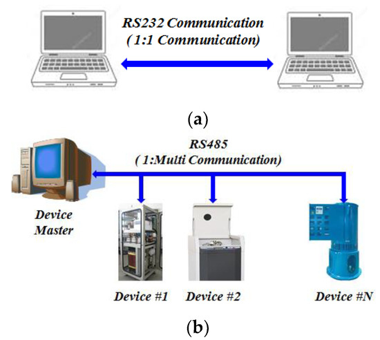
Figure 1.
Representative asynchronous communication method. (a) RS232, (b) RS485.
Table 1 compares the characteristics of the representative asynchronous communication methods of RS232 communication with those of RS485 communication. In the RS485 method, the maximum output voltage is lower than that in the RS232 method, but due to the differential input, the maximum distance range and the highest communication speed are excellent; however, it has the disadvantage of being a half-duplex communication method, which cannot simultaneously transmit and receive in communication [18,19,20,21]. Unlike this, the RS232 method has the advantage of being a full-duplex method, which can transmit and receive at the same time; however, it has the disadvantage of being a three-wire method, in which there is a wire for transmission and a wire for reception.

Table 1.
Comparison of RS232 and RS485 Communication Characteristics.
The RS232 communication method and the RS485 communication method have the disadvantage of being very vulnerable in terms of communication security since it is easy to leak the communications protocol by installing an analyzer of communication data on the communication line.
2.2. The Proposed Asynchronous Communication
Figure 2 shows 3-level communication hardware which can make full-duplex communication with the proposed two-wire communication. The communication transmission signal is determined by the on/off switches: Q1 and Q2. In other words, if both Q1 and Q2 are off, the output is the high impedance status, which cannot make the transmission function in the communication line. If Q1 is on, and Q2 is off, the binary value ‘1’ of serial communication is transmitted, Vs becomes Vdc, and if Q1 is off, and Q2 is on, the binary value ‘2’ of serial communication is transmitted, Vs becomes 0. However, VL voltage appears to be 3-level by the output level of the other party due to the output impedance resistance [22,23,24,25].
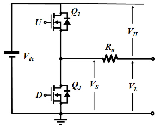
Figure 2.
Proposed 3-level communication hardware.
Figure 3 shows the composition of 3-level communication hardware for bidirectional communication. It is presumed that, since in the proposed topology, the output impedance is larger than that on the communication line, the impedance on the communication line is ignored. VS1 and VS2, reception voltages on Side A and Side B are not determined by the voltage on the transmission side or reception side, but determined by both the voltage on the transmission side and the reception side. In other words, if the voltage on both transmission sides is the same, the transmission voltage is detected, and if it is different, the whole transmission voltage is detected. By this logic structure, the output voltage on the receiving end becomes 3-level according to the transmission information on the transmission side and the reception side. Therefore, the reception information can be obtained by combining the reception information and the transmission information in which the 3-level voltage has been formed according to the transmission status on the transmission side and the reception side.
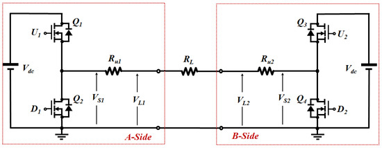
Figure 3.
Hardware configuration for 3-level communication for bidirectional communication.
Figure 4 is a circuit diagram to obtain reception information in the 3-level voltage. As seen in the figure, the level can be judged by constituting a reception signal and a comparator, distributing source voltage so that the level can be differentiated. DH1 consisting of 2/3 of source voltage and a comparator of the reception signal for convenience for 2-level judgment operates by negative logic for 2-level and DL1, consisting of 1/3 of source voltage and a comparator of the reception signal operates by positive logic for 1-level or higher. Thus, it is possible to find a signal relevant to the reception information by constituting it with the exclusive-OR of the logical product of these two signals and the transmission signal, VS1.
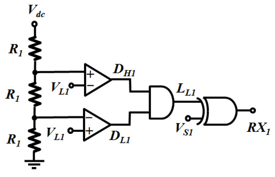
Figure 4.
Reception information extraction circuit.
Figure 5 shows the waveform of operation in the general 485 mode, in which Side B generates transmission information while Side A only receives it. This is a 2-level communication mode in which the voltage on the transmission side and that on the reception side appear to be the same. As seen in Figure 5, the output voltage on Side B, VS2 and the reception voltage on Side A, VL1 become the same form, and the inclusive-OR of the outputs of the two comparators, DH1 and DL1 always become 0. In addition, the exclusive-OR of voltage LL1 and the reception signal, which is always 0 appears as the reception signal.
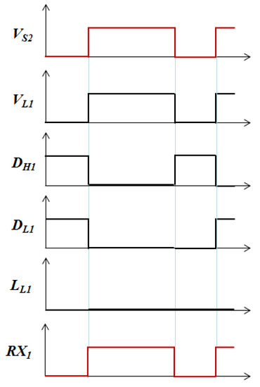
Figure 5.
For one-way communication.
Figure 6 shows the waveform if it is operated in the simultaneous full-duplex communication mode, in which Side B generates transmission data while Side B also generates a transmission signal. To interpret it clearly, the two transmission signals, VS1 and VS2 were defined as those having a 90-degree phase contrast like the figure. In this case, the voltage on the transmission side and that on the reception side appears at different levels with the other party’s information on the transmission side. As seen in Figure 6, the voltage received on Side A, VL1 is formed like the figure by the voltage transmitted on Side A, VS1 and the voltage transmitted on Side B, VS2, and the inclusive-OR of the outputs of two comparators, DH1 and DL1 appears two times in the transmission frequency. Thus, the exclusive-OR of voltage LL1 and reception signal VL1 is the same as the transmission voltage on Side B, VS2. Thus, you can output the desired reception signal from the 3-level reception signals.
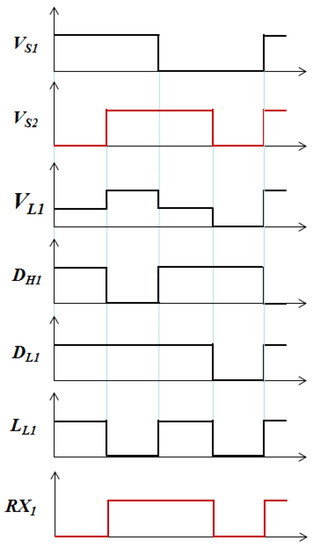
Figure 6.
In simultaneous bidirectional.
3. Simulation and the Result of the Experiment
3.1. Result of Simulation
Figure 7 is a simulation circuit diagram to test the validity of the communication method proposed in this study. The simulation circuit consists broadly of a half-bridge inverter to generate a communication signal, a comparator to detect 3-level, a logical circuit diagram, and the DLL part to generate a series transmission signal by Visual C language.
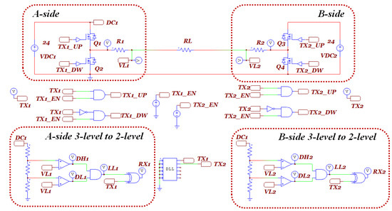
Figure 7.
Simulation circuit diagram.
Figure 8 defined two transmission signals, VS1 and VS2 on Side A and Side B in the same condition as that of Figure 6, that is, the two transmission signals on Side A and Side B have a 90-degree phase contrast. In this case, the voltage on the transmission side and that on the reception side appear at different levels; however, a waveform the same as that in Figure 6 appears, and it was noted that Side A perfectly receives the signal transmitted on Side B.

Figure 8.
Simultaneous bidirectional communication simulation results.
Figure 9 is the result of a simulation to check asynchronous serial communication, in which Side A transmitted the character, ‘U’ by ASCII Code and Side B transmitted the character, ‘U’ by ASCII Code, setting 9600bps, 8-bit data, 1 stop bitter and no-parity.
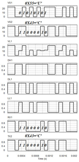
Figure 9.
Simultaneous bidirectional simulation results.
As seen in the figure, as a VS1 series signal on Side A, ASCII Code character ‘U’ is generated, which is 0X55 in a hexadecimal number, while as a VS2 series signal on Side B, ASCII Code character ‘C’ is generated, which is 0X43 in a hexadecimal number. As a signal received by the proposed communication topology by the transmission data of the characters, ‘U’ and ‘C,’ a 3-level reception signal is generated like VL1. At the reception signal, VL1 is determined by two transmission signals VS1 and VS2 in each module. Thus, if you have information about two of the three signals, VL1, VS1, and VS2, you can get the information value of the other signal. Since you can measure the transmission signal and the reception signal you generated in each module, you can get the other party’s transmission signal with information about these two signals. As a characteristic of this method, it is impossible to separate the transmission signals of the two modules from the 3-level signal generated on the communication line.
Especially, even if the same ASCII character is transmitted, the 3-level appearing on the communication line appears in different forms since it is asynchronous communication. Thus, in receiving an important signal, if the receiver operates the transmitter with a secure signal, another device cannot get the accurate transmission data in the middle of the communication line. This is considered a very excellent characteristic in terms of communication security.
3.2. Result of Exiperiment
Figure 10 is a new communication prototype in the 3-level method, which can transmit and receive simultaneously in two-wire communication. This prototype consists broadly of the SMPS part with 9–36 V input range, gate amp part, half-bridge equipment to generate a communication signal, and the comparison equipment and the logic equipment, which receive 3-level input and convert it to 2-level reception information.
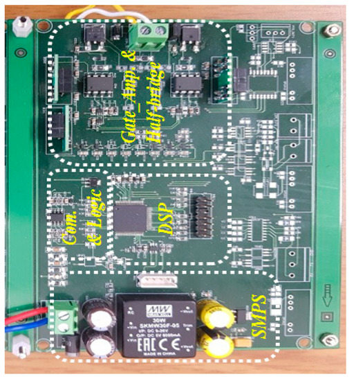
Figure 10.
New three-level communication prototype.
Figure 11 is the result of an experiment in which Side B generates ASCII Code ‘C’ communication data while Side A only receives them, which is the general communication method. As seen in the resulting waveform of Figure 11, this communication method is compatible with the existing communication method.
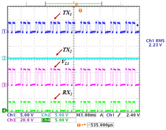
Figure 11.
One-way communication test result.
Figure 12 is the result of an experiment of communication in the same status as the simulation condition of Figure 9. As shown in the resulting waveform of Figure 12, the two transmitters transmit the same data, but the asynchronous communication method is different, so the three-level voltage appearing on the communication line is different. However, it was found that the received data correctly received the transmitted data.
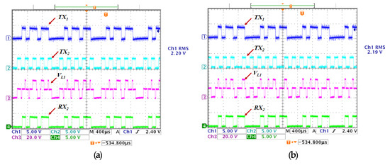
Figure 12.
Simultaneous bidirectional experimental results.
4. Conclusions
In this paper, we propose new communication hardware equipment capable of implementing a full-duplex communication method at the same time, apart from the full-duplex communication method by the time division method.
- At the communication transmitter, two-level signals are generated for data transmission, but due to the characteristics of the proposed communication hardware, three-level electrical signals are generated in the communication line depending on the status of transmission data generated at two transmission data. At the same time, full-duplex communication was achieved.
- Since the voltage of the communication line is indicated by the transmitter transmission data and the receiver transmission data signal, it is considered to be very good in terms of security of communication because only the two devices can analyze the signal information of the communication line.
- It is considered that long-distance communication is possible by increasing the voltage of the transmission line by constructing the transmission circuit with a half-bridge structure.
- It is considered that this data transfer algorithm can be simplified more than the full-duplex communication method by the time division method by implementing a full-duplex communication method at the same time by this topology.
Therefore, this topology is expected to be utilized mainly on the lines requiring communication security and those requiring long distance communication.
Author Contributions
Conceptualization, S.-M.P., S.-J.P. and S.-K.L.; Data curation, S.-M.P. and S.-J.P.; Formal analysis, S.-M.P. and S.-J.P.; Funding acquisition, S.-J.P. and S.-K.L.; Investigation, S.-M.P. and S.-K.L.; Project administration, S.-K.L.; Writing—original draft, S.-J.P.; Writing—review & editing, S.-J.P. and S.-K.L.
Funding
This research was funded by the support of the Korea Institute of Industrials Technology as “Development of Chassis Platform for Semi-autonomous Electric Vehicle with EMS Function” (KITECH NW-19-0050).
Conflicts of Interest
The authors declare no conflicts of interest.
References
- Yan, L.; Frank, R.; Nenad, I. The Paradigm Shift in Smart Manufacturing System Architecture. IFIP Adv. Inf. Commun. Technol. 2017, 488, 767–776. [Google Scholar]
- Mohsen, M.; Marissa, N.; Cadavid, C.; Robert, K. Reference architectures for smart manufacturing: A critical review. J. Manuf. Syst. 2018, 49, 215–225. [Google Scholar]
- Mehmet, H.C.; Tarek, Y.; Osama, A.M. Development and Application of a Real-Time Testbed for Multiagent System Interoperability: A Case Study on Hierarchical Microgrid Control. IEEE Trans. Smart Grid 2018, 9, 1759–1768. [Google Scholar]
- Tarek, K.; Kshirasagar, N.; Amiya, N. A Survey of Communication Protocols for Automatic Meter Reading Applications. IEEE Commun. Surv. Tutor. 2011, 13, 168–182. [Google Scholar]
- Bilal, E.B.; Selcuk, B.; Vehbi, C.G. Collecting smart meter data via public transportation buses. IET Intell. Transp. Syst. 2016, 10, 515–523. [Google Scholar]
- Seong-Ho, P.; Ki-Hong, P.; Young-Chai, K.; Mohamed-Slim, A. Alternate Transmission Relaying Based on Interference Alignment in 3-Relay Half-Duplex MIMO Systems. IEEE J. Sel. Areas Commun. 2012, 30, 1383–1389. [Google Scholar]
- Wei, L.; Chuan, L.; Jian-Dong, L. Achieving Maximum Degrees of Freedom of Two-Hop MIMO Alternate Half-Duplex Relaying System for Linear Transceivers: A Unified Transmission Framework for DF and AF Protocols. IEEE Trans. Veh. Technol. 2015, 64, 2144–2148. [Google Scholar]
- Ashutosh, S.; Philip, S.; Dongning, G.; Daniel, W.B.; Sampath, R.; Risto, W.; Lee, R.E. In-Band Full-Duplex Wireless: Challenges and Opportunities. IEEE J. Sel. Areas Commun. 2014, 32, 1637–1652. [Google Scholar]
- Dingzhu, W.; Guanding, Y. Full-duplex and half-duplex: Power efficiency comparison. Electron. Lett. 2016, 52, 483–485. [Google Scholar]
- Chung, M.; Sim, M.S.; Kim, D.K.; Chae, C.B. Compact Full Duplex MIMO Radios in D2D Underlaid Cellular Networks: From System Design to Prototype Results. IEEE Access 2017, 5, 16601–16617. [Google Scholar] [CrossRef]
- Levy, B.C. A Study of Subtractive Digital Dither in Single-Stage and Multi-Stage Quantizers. IEEE Trans. Circuits Syst. I Regul. Pap. 2013, 60, 2888–2901. [Google Scholar] [CrossRef]
- Briassouli, A.; Strintzis, M.G. Optimal watermark detection under quantization in the transform domain. IEEE Trans. Circuits Syst. Video Technol. 2004, 14, 1308–1319. [Google Scholar] [CrossRef]
- Soummya, K.; José, M.F.M.; Kavita, R. Distributed Parameter Estimation in Sensor Networks: Nonlinear Observation Models and Imperfect Communication. IEEE Trans. Inf. Theory 2012, 58, 3575–3605. [Google Scholar]
- Jiao, Z.; Richard, Y.F.; Shuo, W.; Tao, H.; Zengyi, L.; Yunjie, L. Load Balancing in Data Center Networks: A Survey. IEEE Commun. Surv. Tutor. 2018, 20, 2324–2352. [Google Scholar]
- Ting, W.; Yu, X.; Jogesh, M.; Mounir, H. Achieving Energy Efficiency in Data Centers Using an Artificial Intelligence Abstraction Model. IEEE Trans. Cloud Comput. 2018, 6, 612–624. [Google Scholar]
- Rakesh, R.; Srinivas, A.; Gokhan, G. Power line carrier (PLC) signal analysis of smart meters for outlier detection. In Proceedings of the 2011 IEEE International Conference on Smart Grid Communications (SmartGridComm), Brussels, Belgium, 17–20 October 2011; pp. 291–296. [Google Scholar]
- Yingkayun, K.; Premrudeepreechacharn, S. A power quality monitoring system for real-time detection of power fluctuations. In Proceedings of the 2008 40th North American Power Symposium (NAPS ’08), Calgary, AB, Canada, 28–30 September 2008; pp. 1–5. [Google Scholar]
- Al-Madani, B.; Al-Roubaiey, A.; Al-Shehari, T. Wireless video streaming over Data Distribution Service middleware. In Proceedings of the 2012 IEEE 3rd International Conference on Software Engineering and Service Science (ICSESS), Beijing, China, 22–24 June 2012; pp. 263–266. [Google Scholar]
- Marisol, G.-V.; Pablo, B.V.; Iria, E.A. Adaptive real-time video transmission over DDS. In Proceedings of the 2010 8th IEEE International Conference on Industrial Informatics (INDIN), Osaka, Japan, 13–16 July 2010; pp. 130–135. [Google Scholar]
- Pj, R.; Xinghuo, Y. A Novel Time Independent Asynchronous Communication Protocol & Its Applications. In Proceedings of the IECON 2006—32nd Annual Conference on IEEE Industrial Electronics, Paris, France, 6–10 November 2006; pp. 3574–3579. [Google Scholar]
- Dariusz, K.; Filip, N. Practical Performance Aspects of Using Real-Time Multi-agent Platform in Complex Systems. In Proceedings of the 2013 IEEE International Conference on Systems Man and Cybernetics (SMC), Manchester, UK, 13–16 October 2013; pp. 1121–1126. [Google Scholar]
- RamaKoteswara, R.A.; Pahuja, G.L.; Lather, J.S. Importance measures based risk and reliability analysis of substation automation systems. In Proceedings of the 2014 Annual IEEE India Conference (INDICON), Pune, India, 11–13 December 2004; pp. 1–5. [Google Scholar]
- RamaKoteswara, R.A.; Pahuja, G.L.; Lather, J.S. Risk and reliability analysis of substation automation systems using importance measures. In Proceedings of the 2014 Eighteenth National Power Systems Conference (NPSC), Guwahati, India, 18–20 December 2014; pp. 1–5. [Google Scholar]
- Hamze, H.H.; Meysam, H.; Mohamad, E.H.G. Quantitative Reliability Assessment of Various Automated Industrial Substations and Their Impacts on Distribution Reliability. IEEE Trans. Power Deliv. 2012, 27, 1223–1233. [Google Scholar]
- Amit, S.; Mahesh, B.; Nimish, P.; Himanshu, B.S. Zigbee Based Wireless Data Acquisition System for Underground Mines—A Feasibility Study. In Proceedings of the 2018 IEEE 21st International Symposium on Real-Time Distributed Computing (ISORC), Singapore, 29–31 May 2018; pp. 152–155. [Google Scholar]
© 2019 by the authors. Licensee MDPI, Basel, Switzerland. This article is an open access article distributed under the terms and conditions of the Creative Commons Attribution (CC BY) license (http://creativecommons.org/licenses/by/4.0/).