Abstract
Unmanned aerial vehicles, which are widely used today, require human assistance to meet their energy needs. This dependency disrupts autonomous operation. At this point, wireless power transfer technology offers a promising solution for full autonomy. These vehicles can be easily charged by contactless power transfer between magnetic couplers in seemingly impossible locations. Coupler configurations are critical due to the size constraints of these vehicles. In current studies, analyses of transfer efficiency are conducted using one or two parameters. In this study, in addition to the coupler configuration, the effects of air gap, duty cycle, and magnetic core on efficiency were analyzed together. The performance of couplers with rectangular, circular, and double-D configurations was investigated through comprehensive simulations and experiments. The AC and DC efficiencies of the wireless power transfer system were analyzed by performing 46 experiments, while the operating frequency of the system was between 95 and 105 kHz, the input power was around 250 W. Simulations of the system and couplers were performed in MATLAB and Ansys. In the experiments, the highest AC efficiency was 98.9%, and the DC efficiency was 86.7%. The error margins in MATLAB and Ansys models are less than 1% and 4%, respectively.
1. Introduction
Unmanned aerial vehicles (UAVs) have a wide range of applications, including military, logistics, agriculture, natural disaster response, industry, archaeology, cartography, and mining [1]. The increasing demand for UAVs that can be remotely controlled or operate autonomously results in higher energy requirements for these vehicles. Although significant developments in energy storage techniques have occurred in recent years, battery capacities still limit the flight times of UAVs [2]. This situation reduces operational efficiency and disrupts mission continuity during long-term missions. Additionally, traditional charging methods necessitate post-landing battery replacement and a wired connection, thereby reducing operational times and precluding fully autonomous operation. In this context, wireless power transfer (WPT) emerges as a promising solution that enables UAVs to be charged in a contactless, safe, and automatic way [3].
Wireless power transfer systems used in UAVs generally perform with inductive coupling and magnetic resonance principles [4]. In these methods, the electromagnetic field is matched between the primary and secondary windings, enabling wireless power transfer. However, parameters such as air gap, coupler geometry, alignment error, and coupling coefficient (k) significantly affect wireless power transfer performance [5]. Also, duty cycle (d), changes in operating frequency, switching losses, and conduction losses are other factors that affect system performance in inverters. In this context, researchers have experimentally tested various coupler structures to enhance transfer efficiency, particularly over the recent decade [6]. As a result of these analyses, different transmitter–receiver coupler geometries have emerged. Examples of these are circular, rectangular (rect), double-D (DD), triple-D (DDD), and helical configurations. The primary goal of coupler designs is to achieve high-efficiency power transfer within a light and compact system.
This study aims to comprehensively compare different wireless power transfer couplers used in UAV applications and evaluate the system performance in terms of power transfer capacity, efficiency, operating frequency, air gap, duty cycle, interoperability, and magnetic core presence. In this manner, various coupler topologies were compared by examining experimental studies from the literature over the recent decade. The effects of different coupler configurations on WPT systems for UAVs were examined through experimental and simulation-based studies. Experiments were conducted across different air gaps and duty cycles in the 95–105 kHz frequency band, both with and without a magnetic core. The WPT system and coupler models, designed in MATLAB/Simulink R2021b and Ansys/Maxwell 3D Design 2022R1 software, were verified against experimental results. As a result of the studies, the coupler efficiency (AC-AC) and the overall system efficiency (DC-DC) were obtained separately.
In conclusion, this study provides a technical comparison of existing coupler architectures for UAV-specific wireless charging systems. It systematically evaluates the performance of a series of parameters, along with coupler geometry, in WPT systems. The results of the study serve as a comprehensive reference for both academic researchers and design engineers useful for analyzing the efficiency of the UAV wireless charging systems.
In the second section of this study, related work in the literature is included. In the third section, the designed WPT system is presented, and in the fourth section, its loss and circuit analysis are presented. Section five includes experiments and simulation studies. In the sixth section, the detailed analysis of the results and model verification steps is shared. In the seventh and last section, critical facts of this comprehensive study are emphasized.
2. Related Work
Coupler configurations play a crucial role in wireless power transfer. Especially in UAV applications, there are certain restrictions, such as coupler dimensions, weight, and power density. Due to these limitations, researchers have tailored their designs to accommodate various coupler configurations and dimensions, power levels, frequencies, air gaps, and magnetic core parameters. In this context, experimental studies from the literature over the recent 10 years have been comprehensively evaluated and summarized in Table 1.

Table 1.
Comprehensive Comparison of Coupler Configurations used in UAV WPT Systems (Freq: Frequency, Eff DC: DC-DC Efficiency, Eff AC: AC-AC Efficiency, Config: Configuration, Tx Dim: Transmitter Dimension, Rx Dim: Receiver Dimension, Ref: Reference).
The output power of the WPT system varies between 6.6 and 625 W in the conducted studies. Depending on the UAV’s dimensions, power transfer was carried out between 12 and 500 kHz. The air gap was also 0 mm when rotational acceleration was used, and it ranged from 0 to 500 mm in other cases, depending on the coupler configurations. While coupler pairs with the same configuration were used in the studies, different Tx/Rx configurations are also available, depending on the couplers’ interoperability. The main types of couplers used are circular, rectangular, DD, DDD, and helical. While some studies employed nested circular and rectangular couplers, others utilized multi-channel couplers to transfer power contactlessly. In fact, in some studies, the receiver coupler is specifically designed to accommodate the shapes of UAV landing gear or propeller protection. In some studies, the magnetic core was not used at all; in others, it was used only on the primary or secondary sides. It is an expected result that the coupler efficiency increases when magnetic cores are used on both sides of the coupler. In studies, coupler sizes also vary, depending on the UAV capacity. Dimensions increase to 800 mm in transmitter coupler designs. Receiver coupler sizes vary between 43 and 475 mm in diameter in circular configurations, and between 30 × 22 mm and 280 × 280 mm in rectangular configurations. When the studies are evaluated as a whole, the AC-AC efficiency ranges from 82.1% to 97.7%. DC-DC efficiency varies between 52% and 91.9%. In a limited number of studies, DC-DC and AC-AC efficiencies have been analyzed together.
Table 1 presents the above results and allows for the following inferences:
- Circular and rectangular configurations were used in almost all of the studies.
- Interoperability analysis was performed in 28% of the studies.
- Magnetic cores were used on both sides in 26% of the studies.
- Both system and coupler efficiencies were examined in 15% of the studies.
- The air gap is between 100 and 200 mm in 15% of the studies.
- The input power is between 200 and 300W in 13% of the studies.
- The operating frequency is around 100 kHz in 7% of the studies.
- Any analysis of the duty cycle was found.
Circular and rectangular coupler configurations are adopted based on the analyses mentioned above. To perform interoperability analysis, the DD configuration was chosen for rectangular couplers, and a circular configuration was chosen for circular couplers. For all these configurations, the frequency range of 95–105 kHz, the air gap of 100–200 mm, the duty cycles of 100% and 75%, and the magnetic core parameters were determined.
3. System Overview
The WPT system designed for UAVs consists of a full-bridge inverter, a series–series compensation system, a full-wave rectifier, and a load. In traditional WPT systems, a power factor correction (PFC) converter is used in addition to the AC source at the input. In this system, the DC source powers the full-bridge inverter. The control card in the inverter determines the operating frequency, deadtime, and pulse-width modulation (duty cycle) of the system. Code Composer Studio software was used to program all these parameters. The compensation system has a series configuration. Transmitter and receiver couplers with circular, rectangular, and DD geometries were used in the compensation system. A full-wave rectifier and filter capacitor follow the compensation system. A resistive load is used at the output to avoid long charging times. There are separate fans to cool the inverter and the full-wave rectifier. Differential current and voltage probes measure the compensation system input and output, as well as the full-wave rectifier output. Voltage, current, and power values of these subcircuits were recorded with an oscilloscope. A thermal camera observed the temperature values of the WPT system during the experiments. The block diagram of the WPT system is shown in Figure 1.
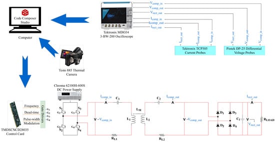
Figure 1.
Block Diagram of the WPT System.
The primary objective of this study is to examine and compare the coil performances with different geometries used in UAV wireless power transfer applications, both experimentally and through simulation. In this context, coils with circular, rectangular, and DD configurations were used. The geometries of the couplers designed with Litz wire are given in Table 2. In the experiments, the performance of couplers with the same geometry as the transmitter (Tx) and receiver (Rx) was examined, and DD-rectangular or circular coils with different diameters were tested for interoperability. The coupler types used in the experiments are given in Figure 2.
Table 2.
Magnetic coils used in experiments.
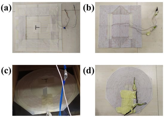
Figure 2.
Coupler Configurations. (a) Rect, (b) DD, (c) Circ1, (d) Circ2.
In addition to coil geometries, the effects of different parameters on system efficiency were also examined. The first of these parameters is the duty cycle. The square-wave voltage supplied by the inverter to the compensation system contains harmonics that vary with the duty cycle, causing noise. These harmonics reduce efficiency by distorting power. Studies have shown that the efficiency is maximum at a 75% duty cycle, and the transferred power is maximum at 100% [46]. System efficiency was examined at 75% and 100% duty cycles for all coupler configurations. Another parameter whose effect on efficiency is examined is the magnetic core. I-shaped soft ferrites made of manganese–zinc (Mn-Zn) with dimensions of 102 × 35.7 × 7 mm were used to form 300 × 300 × 7 mm magnetic cores. In the presence of a magnetic core, experiments were carried out at 150 and 200 mm air gaps, and in its absence, at 100 and 150 mm air gaps. In the experiments, the operating frequency ranges from 95 to 105 kHz. The input power of the system is approximately 250 Watts. As a result, a total of 46 experiments were conducted, varying the above-mentioned transmitter and receiver coil geometries, duty cycle, air gap, and magnetic core presence.
4. WPT System Circuit and Loss Analysis
The primary purpose of WPT systems is to maximize system efficiency while maintaining a compact design. For this, it is necessary to analyze the losses that may occur in the system and the mathematical model of the system. In this section, the power losses of the inverter and full-wave rectifier that comprise the system, as well as the mathematical model of the compensation system, will be analyzed.
The common power losses in the inverter are due to duty cycle, switching, conduction, and gate losses. In the inverter, the pulse-width modulation (PWM) signal, which determines the operating frequency of the system, is a symmetrical square wave and contains harmonics depending on the duty cycle. The Fourier expansion and total harmonic distortion (THD) analysis of the symmetric square wave are given in Equation (1) [46].
where , , a, , d and h are bus and peak-to-peak bus voltage of the inverter, harmonic of the symmetric square wave, fundamental radial frequency of the signal, duty cycle and harmonic index, respectively. The zeroth harmonic () is equal to zero due to the symmetry property. Harmonic amplitudes with even indices are zero due to the sine function. When calculating harmonic indices, the leading indices are more dominant since there is an index value in the denominator. As the index increases, the value of the harmonic decreases. THD, which varies depending on the harmonic index and therefore the duty cycle, is minimum when the duty cycle is 75%. THD adds the distortion power term to the apparent power (S), which has typically real (P) and reactive (Q) power components, as in Equation (2) [47]. The introduction of the distortion power (D) causes the efficiency to decrease. Therefore, the experiments were carried out at 100% and 75% duty cycles for power and efficiency maximization scenarios, respectively.
Other losses in the inverter arise from the switching elements and the body diodes in their structure [48]. Conduction losses are given in Equation (3). Although the inverter output current () is squared in field-effect transistor (FET) conduction losses (), these losses are low since the on-state resistance of the inverter FETs (RDSon) is in the order of mΩ. Also, the ratio of the inverter output voltage () to the input voltage () is also less than one. On the other hand, in diode conduction losses , since the diode forward voltage () is multiplied by the average current (), the dominant loss occurs in this case.
Although not as significant as conduction losses, switching losses () also have a substantial impact on efficiency. These losses, which occur when the switching elements are on () and off (), are given in Equation (4). Since the WPT operation frequency () is 100 kHz and the switching element fall () and rise () times are in the order of ns, switching losses remain low compared to conduction losses.
Gate losses (), which are negligible compared to conduction and switching losses, are given in Equation (5). Since the total gate charge () is in the order of nC, gate losses are often not considered.
As with inverter losses, there are also diode conduction losses in the full-wave rectifier. Two diodes are conducting in the positive and negative cycles of the AC voltage. Therefore, full-wave rectifier losses are calculated by multiplying the diode conduction losses in Equation (3) by two.
In WPT systems, compensation systems basically have series–series, series–parallel, parallel–series, and parallel–parallel configurations. Since series–series compensation is adopted in this study, the mathematical analysis of this topology will be made according to the compensation circuit in Figure 1. Primary and secondary impedance are defined as in Equation (6).
Equation (8) is rearranged, and the compensation system output current is written in terms of input current as in Equation (9).
According to all these analyses, the efficiency () of the series–series compensation system, the ratio of the output () and input () power are obtained as in Equation (12).
5. Simulation Modeling and Experimental Methodology
Modeling the WPT system according to the design criteria will be a guide for this study and future studies. In this manner, simulation studies were conducted using MATLAB/Simulink and Ansys/Maxwell 3D Design software for the WPT system, which comprises an inverter, a series–series compensation system, a full-wave rectifier, and a load. The developed models via Simulink and Ansys are as shown in Figure 3 and Figure 4.
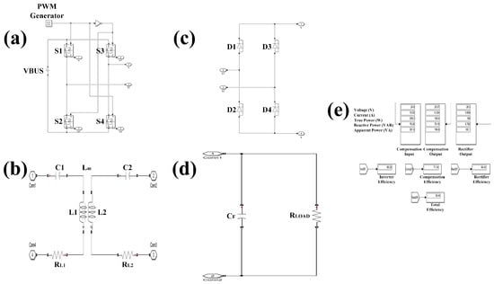
Figure 3.
WPT Simulink Model. (a) Inverter, (b) Compensation, (c) Rectifier, (d) Filter&Load, (e) Efficiency Display.
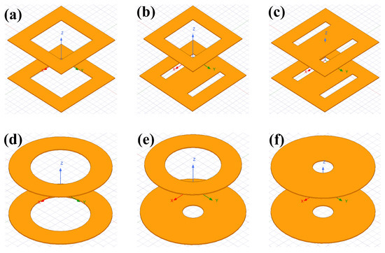
Figure 4.
WPT Coupler Ansys Model. (a) Rect-Rect, (b) DD-Rect, (c) DD-DD, (d) Circ1-Circ1, (e) Circ2-Circ1, (f) Circ2-Circ2.
In the Ansys Maxwell 3D Design interface, coils with circular, rectangular, and DD geometry given in Table 2 are modeled according to their inner and outer diameters and number of turns. Coil trays, used in experiments to prevent misalignments and ensure an identical design, are also included in each model. The simulation input parameters for the transmitter and receiver coils include frequency, air gap, and the presence of a magnetic core. The self-inductances of the coils and the mutual inductance between the coils, as well as the coupling coefficient, are the output parameters. At the beginning of the experiments, the aim was to verify the models by comparing the simulation output parameters with measurement results obtained at a 100 kHz frequency using an LCR meter.
In the MATLAB/Simulink software, the whole WPT system was modeled. Efficiency analysis was performed by simulating the voltage, current, and power ratings of each subsystem. Initially, the circuit of the series–series compensation system was analyzed using the MATLAB script, and the efficiency and input impedance characteristics of the system were obtained between 50 kHz and 150 kHz. For each scenario, the operating frequency of the system was determined based on the efficiency and input impedance graphs. This (resonance) frequency is also the operating frequency of the WPT system developed in Simulink. In addition to frequency, other input parameters of the Simulink model are input voltage, duty cycle, and electrical ratings of the circuit elements. The aim is to verify the model by analyzing the input and output voltages, currents, and power ratings of the subsystems, considering all these parameters. The “ode45 (Dormand-Price)” solver was used in all analyses, with 1 ns steps. The same procedure was applied in all simulation studies.
Forty-six experiments were conducted to investigate the effects of different coil geometries on efficiency within the scope of this study. The primary purpose is to compare the geometries of the couplers. In addition to this comparison, the effects of parameters, such as air gap, duty cycle, and magnetic core presence, were also observed in experiments, and comprehensive research was conducted. The test scenarios are summarized in Table 3. For example, in tests 1–4, rectangular coils were used as transmitting and receiving coils. These tests were performed without using a magnetic core at air gaps of 100 and 150 mm. The effects of 75% and 100% duty cycles were tested in each air gap. In tests numbered 5–8, the same processes were performed in the presence of a magnetic core. Although it was intended to carry out experiments in two different air gaps for all coil pairs given in Table 3, experiments were carried out in coil pair number 7 with only a 150 mm air gap. To obtain stable results, all measurements for each experiment were taken after 5 min. In this way, both efficiency fluctuations and errors caused by cooling elements are eliminated.
Table 3.
Magnetic coil configurations in the experiments.
The experimental setup is shown in Figure 5. The TDINV3500P100-KIT model, a single-phase, high-frequency full-bridge inverter with 3.5 kW power and a 150 kHz frequency range, was used at the beginning of the WPT system. Frequency, duty cycle, and dead time parameters were set using the F28035 Piccolo control card within the inverter. TP65H070G4PS gallium nitride (GaN) FETs are used as switching elements in the inverter. These switching elements have lower resistance than their silicon carbide (SiC) counterparts, offering more efficient switching and wider frequency operation. Energy to the inverter was provided by the Chroma 62100H-600S programmable DC power supply, which has a 600 V, 17 A, 10 kW rating. The compensation system consists of capacitor banks and coils with circular, rectangular, and DD geometries. In this study, since WPT via magnetic resonance was adopted, capacitor banks were designed in accordance with the coupler pairs. Thus, the voltage stress on the capacitors decreased. In all coil designs, 2.4 mm diameter, 38 AWG Litz wire consisting of 300 twisted wires was used. In the full-wave rectifier stage, APT30S20B(G) model high-voltage Schottky diodes with 200 V, 45 A ratings were used. In the last stage, a 5 Ω load consisting of a series of resistors was used. Tektronix TCP305 differential current and Pintek DP-25 differential voltage probes were used to measure voltage, current, and power ratings of the subsystems. Ratings regarding wireless power transfer were recorded by observing current, voltage and power signals with a Tektronix MDO34 oscilloscope. In this way, the total efficiency (DC-DC) of the WPT system was obtained by measuring the input power of the system and the output power on the load in terms of real power (W). AC-AC efficiency is the compensation system efficiency and was determined from apparent power (VA) measurements at the input and output of the compensation system. The inverter and full-wave rectifier are cooled by fans for improved efficiency. The WPT system temperatures were monitored and recorded by a Testo 885 thermal camera, and the effects of subsystem temperatures on efficiency were investigated.
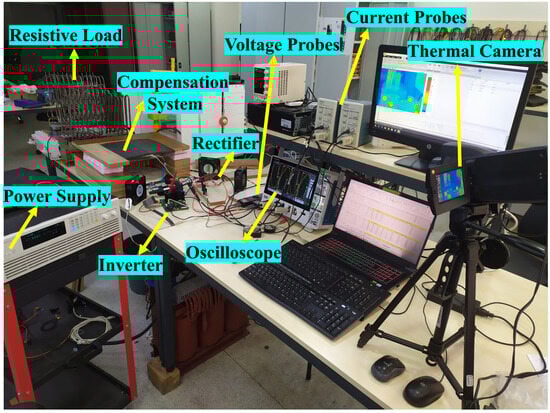
Figure 5.
WPT System Test Setup.
6. Results and Discussion
In this study, a total of 46 experiments were conducted to compare coupler geometries and see the effects of different parameters on the WPT system. In this section, measurement and test results of the WPT system, a comprehensive analysis of these results, verification of the models developed in MATLAB/Simulink and Ansys/Maxwell 3D Design software, and model error rates are presented.
In the experiments, the operating frequency varies between 95 and 105 kHz. For this reason, measurements of the compensation system components were made with an LCR meter at a frequency of 100 kHz for every experiment. To obtain stable results, it was confirmed using a thermal camera that the component temperatures were below 30 °C before each experiment. Table 4 shows the compensation system measurements.
Table 4.
Compensation System Measurements.
The experimental procedure is given in Table 3. The large number of experiments enables a detailed and comparative analysis. For example, in tests 1–4, the effects of duty cycle and air gap on a rectangular coil pair were investigated. In tests 5–8, the same effects were examined in the presence of a magnetic core. In tests 9–16, the interoperability of the DD-Rect coil pair was evaluated for duty cycle, air gap, and magnetic core parameters.
Figure 6 contains all the experimental results. In the figure, parts (b–e) show the test results without a magnetic core, and parts (f–i) show the test results with a magnetic core. Since there are no 100 mm test results for the Circ2-Circ2 configuration, data for this configuration cannot be included in parts (c) and (e).
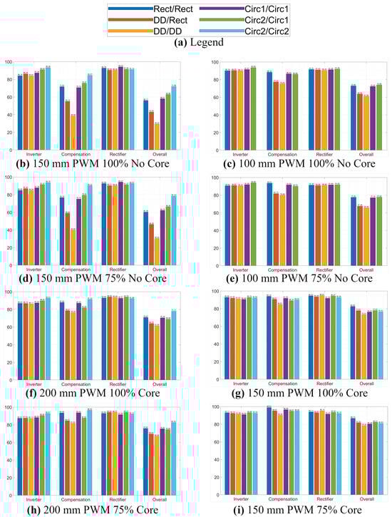
Figure 6.
Experimental Test Results of WPT System Components.
The main purpose of the study is to comprehensively investigate the effects of various parameters and coupler configurations on efficiency. It is necessary to analyze the efficiency of the compensation system for coupler pair performance. Experiments indicate the following conclusions about coupler configurations.
- As the air gap increases, the highest efficiency is achieved with the Circ2-Circ2 coil pair, regardless of the magnetic core or duty cycle.
- As the air gap decreases, the Rect-Rect coil pair achieves the highest efficiency, regardless of the magnetic core or duty cycle.
- In all scenarios, the DD-DD pair has the lowest efficiency.
- At the same air gap (150 mm), the Circ2-Circ2 pair is most efficient when there is no magnetic core, and the Rect-Rect pair is most efficient when the magnetic core is present.
- In the same air gap, the interoperability of the Circ2-Circ1 pair in the absence of a magnetic core and the DD-Rect pair in the presence of a magnetic core is high.
- Among the coupler pairs of the same size in the same air gap, Rect-Rect is slightly superior to Circ1-Circ1 without a magnetic core, but it is clearly superior with a magnetic core.
- When a magnetic core is added to the system in the same air gap, the efficiency differences between coupler pairs decrease.
- The maximum AC-AC efficiency achieved was 98.94% in the scenario with a 150 mm air gap, a 75% duty cycle, and a magnetic core.
A performance comparison of coupler pairs across duty cycle and magnetic core changes for the same air gap (150 mm) is presented in Table 5. While the average efficiency rating weighs half of the total performance, the remaining half is divided equally among the rankings obtained in the experiments. Accordingly, the Circ2-Circ2 pair obtained the highest score, followed by the Rect-Rect pair. While the Circ1-Circ1 and Circ2-Circ1 pairs shared the same score, the DD-Rect pair was far behind them. The DD-DD pair performed the worst.
Table 5.
Performance Comparison of the Coupler Configurations at a 150 mm Air Gap.
To illustrate the efficiency analysis of the components of the WPT system, the average changes in the inverter, compensation, rectifier, and total efficiencies across the air gap, duty cycle, and magnetic core triangle are presented in an infographic in Figure 7. The results are summarized below.
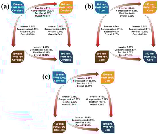
Figure 7.
Efficiency Changes of the WPT System Components for All Tests. (a) Coreless Comparison, (b) Core Comparison, (c) Air Gap Comparison.
- Inverter efficiencies increase as the air gap decreases, independent of the magnetic core and duty cycle. When the magnetic core is added to the system at the same air gap and duty cycle, the inverter efficiency increases again. On the other hand, when the duty cycle is reduced from 100% to 75% under the same air gap and magnetic core conditions, the increase in efficiency remains below 1%. The reason for the increase in inverter efficiency in all these cases is the higher input impedance resulting from increased mutual inductance, and the decrease in conduction and switching losses due to lower current.
- The efficiencies of the compensation system were analyzed in detail above for each coupler pair. Regardless of the coupler pairs, the highest sensitivity to the presence of an air gap or a magnetic core is observed in the compensation system due to mutual inductance. In the same air gap, the efficiency of the compensation system increases when the duty cycle is reduced from 100% to 75% because harmonics in the inverter output voltage (compensation system input voltage) depend on the duty cycle, independent of the magnetic core.
- The differences in rectifier efficiency compared to other components of the system are very small.
- The dominant factor in the overall efficiency of the WPT system is the compensation system.
- The maximum DC-DC efficiency achieved was 86.70% in the scenario with a 150 mm air gap, a 75% duty cycle, and a magnetic core.
Table 6 presents the results from the experiments, based on Table 1, which compares UAV WPT systems in the literature. In addition to the literature, this table also includes a duty cycle section. In terms of coupler performance, AC-AC efficiencies are generally above 90%. In five scenarios, the efficiency exceeded 94%. In DC-DC efficiency, the 80% level was exceeded in the same scenarios.
Table 6.
Experimental Results of Coupler Configurations to be used in UAV WPT Systems (Tx Dim: Transmitter Dimension, Rx Dim: Receiver Dimension).
In the MATLAB/Simulink interface, all subcircuits of the WPT system are designed as shown in Figure 3. The input impedance and efficiency characteristics of the compensation system were obtained by analytical modeling in MATLAB, according to frequency. In this manner, the operating frequency of the simulation model was determined, and simulations were conducted with the input voltage held constant. Efficiencies were calculated by simulating the voltage, current, apparent, real, and reactive power ratings of each subsystem. In order to perform comprehensive analyses, the “ode45 (Dormand-Prince)” solver was used in each experiment with 1 ns steps. All simulation results are shared in Table A1 and Table A2 in Appendix A.
Transmitter and receiver coils were designed in Ansys/Maxwell 3D Design according to the coil dimensions given in Table 2. Due to long simulation times and high computational costs, designs focused on geometry rather than the number of windings. In other words, the suitable geometry was selected, which includes all windings instead of each winding, as seen in Figure 4. In simulation studies, the self-inductance of each coil, the mutual inductances of the coils, and the coupling coefficient were calculated. The results of simulation studies conducted in Ansys for various coil geometries and configurations are presented in Table A3 of Appendix A.
Simulation results of the coupler and WPT system designed in Ansys and Simulink are given in comparison with the experimental results in Table A1 through Table A3. In order to verify both the coupler designs in Ansys software and the WPT system efficiencies in Simulink software, the root mean squared error (RMSE) analysis given in Equation (13) must be performed. Ei, Si and n are ith experimental and simulation results and sample size, respectively.
Since the inverter, compensation system, rectifier, and total efficiency are considered in the Simulink RMSE analysis, the sample size (n) is four. In the Ansys RMSE analysis, the sample size is three because calculations are made based on self and mutual inductances. Since the coupling coefficient is independent of the inductance values, the difference between the experimental and simulation results is valid in the RMSE analysis. RMSE analyses for Simulink and Ansys simulations are given in Table A4 and Table A5 in Appendix B, respectively. In Simulink, the margin of error for individual efficiency values varies between 0.02% and 1.22%. For all efficiency values, the margin of error is calculated to be a minimum of 0.1201% and a maximum of 0.8137%. In Ansys, the margin of error for individual inductance values varies between 0.0001% and 5.6878%. In total, these values are calculated as a minimum of 0.4362% and a maximum of 4.0077%. Coupling coefficient error rates vary between 0.0008% and 0.0145%. Thus, it has been revealed that the developed models will guide future studies.
7. Conclusions
In this study, coupler configurations used in wireless power transfer systems for unmanned aerial vehicles were comprehensively examined. In addition to coupler configurations, the effects of air gap, duty cycle, and magnetic core presence on the transfer efficiency in power transfer using the resonant inductive method were analyzed. While the input power of the system is approximately 250 W, the operating frequency ranges from 95 to 105 kHz. Experiments were conducted with and without a magnetic core at 100% and 75% duty cycles.
According to the results of the comprehensive analysis, the highest AC-AC and DC-DC efficiencies were 98.9% and 86.7%, respectively, at a 150 mm air gap, a 75% duty cycle, and with a magnetic core presence. Considering all experiments, as the air gap increases, the Circ2-Circ2 coupler pair has the highest efficiency; as the air gap decreases, the Rect-Rect coupler pair has the highest efficiency. Although the highest AC-AC and DC-DC efficiencies were achieved in the Rect-Rect configuration in the experiments, the Circ2-Circ2 configuration is the winner in terms of overall performance. The DD-DD configuration showed the lowest performance in all stages. According to the interoperability analysis, the performance of the Circ2-Circ1 configuration is significantly higher than the performance of the DD-Rect configuration.
Models were developed using Ansys/Maxwell 3D Design and MATLAB/Simulink software, based on the transmitter–receiver coupler configurations and WPT system designs. The models were validated by comparing the simulation results with the experimental results. Accordingly, the total error rates of the models designed in Ansys vary between 0.4362% and 4.0077%, while the total error rates of the models developed in MATLAB vary between 0.1201% and 0.8137%.
In conclusion, the findings show the significant effects of parameters such as coupler configuration, air gap, duty cycle, and magnetic core on the efficiencies of wireless power systems used in UAVs. This study will support designers and researchers in efficiency analysis. In UAV WPT designs, parameters such as weight, size, and misalignment are of great importance, as well as efficiency. According to the results, we plan to perform coupler geometry optimization, including weight and misalignment analyses, in future studies.
Author Contributions
Conceptualization, M.Y. and E.Ç.; methodology, M.Y.; software, M.Y.; validation, M.Y.; formal analysis, M.Y.; investigation, M.Y.; resources, M.Y. and H.A.; data curation, M.Y. and H.A.; writing—original draft preparation, M.Y.; writing—review and editing, E.Ç. and H.A.; visualization, M.Y.; supervision, E.Ç. and H.A.; project administration, M.Y. All authors have read and agreed to the published version of the manuscript.
Funding
This research received no external funding.
Institutional Review Board Statement
Not applicable.
Informed Consent Statement
Not applicable.
Data Availability Statement
The original contributions presented in this study are included in the article. Further inquiries can be directed to the corresponding author.
Conflicts of Interest
The authors declare no conflicts of interest.
Appendix A
The results of simulation studies conducted in Ansys and Simulink are given in this section.
Table A1.
MATLAB Simulation Results for Rectangular and DD Coupler Configurations.
Table A2.
MATLAB Simulation Results for Circular Coupler Configurations.
Table A3.
Ansys Simulation Results for Coupler Configurations.
Appendix B
RMSE results, which indicate the error rate of simulation studies made using Ansys and Simulink software, are presented in this section.
Table A4.
RMSE Analysis of MATLAB/Simulink Models (Exp No: Experiment Number, Inv: Inverter, Comp: Compensation System, Rect: Rectifier, Tot: Total, Ave: Average).
Table A5.
RMSE Analysis of Ansys/Maxwell 3D Design Models (Ave: Average).
References
- Mou, X.; Gladwin, D.; Jiang, J.; Li, K.; Yang, Z. Near-Field Wireless Power Transfer Technology for Unmanned Aerial Vehicles: A Systematical Review. IEEE J. Emerg. Sel. Top. Ind. Electron. 2023, 4, 147–158. [Google Scholar] [CrossRef]
- Rong, C.; Duan, X.; Chen, M.; Wang, Q.; Yan, L.; Wang, H.; Xia, C.; He, X.; Zeng, Y.; Liao, Z. Critical Review of Recent Development of WPT Technology for UAVs. IEEE Access 2023, 11, 132982–133003. [Google Scholar]
- Chen, K.; Zhang, Z. In-Flight Wireless Charging: A Promising Application-Oriented Charging Technique for Drones. IEEE Ind. Electron. Mag. 2024, 18, 6–16. [Google Scholar]
- Gliga, M.-R.; Munteanu, C.; Giurgiuman, A.; Constantinescu, C.; Andreica, S.; Pacurar, C. Design, Simulation, Construction and Experimental Validation of a Dual-Frequency Wireless Power Transfer System Based on Resonant Magnetic Coupling. Technologies 2025, 13, 442. [Google Scholar] [CrossRef]
- Bae, H.; Park, S. Design of an Integrated Near-Field Communication and Wireless Power Transfer Coupler for Mobile Device Applications. Technologies 2025, 13, 207. [Google Scholar] [CrossRef]
- Chittoor, P.K.; Chokkalingam, B.; Mihet-Popa, L. A Review on UAV Wireless Charging: Fundamentals, Applications, Charging Techniques and Standards. IEEE Access 2021, 9, 69235–69266. [Google Scholar] [CrossRef]
- Junaid, A.B.; Lee, Y.; Kim, Y. Design and implementation of autonomous wireless charging station for rotary-wing UAVs. Aerosp. Sci. Technol. 2016, 54, 253–266. [Google Scholar] [CrossRef]
- Campi, T.; Dionisi, F.; Cruciani, S.; De Santis, V.; Feliziani, M.; Maradei, F. Magnetic field levels in drones equipped with Wireless Power Transfer technology. In Proceedings of the Asia-Pacific International Symposium on Electromagnetic Compatibility (APEMC), Shenzhen, China, 18–21 May 2016; pp. 544–547. [Google Scholar]
- Wang, C.; Ma, Z. Design of wireless power transfer device for UAV. In Proceedings of the IEEE International Conference on Mechatronics and Automation, Harbin, China, 7–10 August 2016; pp. 2449–2454. [Google Scholar]
- Ke, D.; Liu, C.; Jiang, C.; Zhao, F. Design of an effective wireless air charging system for electric unmanned aerial vehicles. In Proceedings of the IECON 2017—43rd Annual Conference of the IEEE Industrial Electronics Society, Beijing, China, 29 October–1 November 2017; pp. 6949–6954. [Google Scholar]
- Campi, T.; Cruciani, S.; Feliziani, M. Wireless Power Transfer Technology Applied to an Autonomous Electric UAV with a Small Secondary Coil. Energies 2017, 11, 352. [Google Scholar] [CrossRef]
- Song, C.; Kim, H.; Kim, Y.; Kim, D.; Jeong, S.; Cho, Y.; Lee, S.; Ahn, S.; Kim, J. EMI Reduction Methods in Wireless Power Transfer System for Drone Electrical Charger Using Tightly Coupled Three-Phase Resonant Magnetic Field. IEEE Trans. Ind. Electron. 2018, 65, 6839–6849. [Google Scholar] [CrossRef]
- Jawad, A.M.; Jawad, H.M.; Nordin, R.; Gharghan, S.K.; Abdullah, N.F.; Abu-Alshaeer, M.J. Wireless Power Transfer with Magnetic Resonator Coupling and Sleep/Active Strategy for a Drone Charging Station in Smart Agriculture. IEEE Access 2019, 7, 139839–139851. [Google Scholar] [CrossRef]
- Campi, T.; Cruciani, S.; Maradei, F.; Feliziani, M. Wireless Charging System Integrated in a Small Unmanned Aerial Vehicle (UAV) with High Tolerance to Planar Coil Misalignment. In Proceedings of the 2019 Joint International Symposium on Electromagnetic Compatibility, Sapporo and Asia-Pacific International Symposium on Electromagnetic Compatibility (EMC Sapporo/APEMC), Tokyo, Japan, 3–7 June 2019; pp. 601–604. [Google Scholar]
- Han, W.; Chau, K.T.; Jiang, C.; Liu, W.; Lam, W.H. Design and Analysis of Quasi-Omnidirectional Dynamic Wireless Power Transfer for Fly-and-Charge. IEEE Trans. Magn. 2019, 55, 8001709. [Google Scholar] [CrossRef]
- Yang, C.; He, Y.; Qu, H.; Wu, J.; Hou, Z.; Lin, Z.; Cai, C. Analysis, design and implement of asymmetric coupled wireless power transfer systems for unmanned aerial vehicles. AIP Adv. 2019, 9, 025206. [Google Scholar] [CrossRef]
- Cheng, C.; Li, W.; Zhou, Z.; Deng, Z.; Mi, C. A Load-Independent Wireless Power Transfer System with Multiple Constant Voltage Outputs. IEEE Trans. Power Electron. 2020, 35, 3328–3331. [Google Scholar]
- Zhang, H.; Chen, Y.; Jo, C.-H.; Park, S.-J.; Kim, D.-H. DC-Link and Switched Capacitor Control for Varying Coupling Conditions in Inductive Power Transfer System for Unmanned Aerial Vehicles. IEEE Trans. Power Electron. 2021, 36, 5108–5120. [Google Scholar] [CrossRef]
- Yan, Y.; Shi, W.; Zhang, X. Design of UAV wireless power transmission system based on coupling coil structure optimization. Eurasip J. Wirel. Commun. Netw. 2020, 67, 2020. [Google Scholar]
- Cai, C.; Wang, J.; Nie, H.; Zhang, P.; Lin, Z.; Zhou, Y.-G. Effective-Configuration WPT Systems for Drones Charging Area Extension Featuring Quasi-Uniform Magnetic Coupling. IEEE Trans. Transp. Electrif. 2020, 6, 920–934. [Google Scholar]
- Gordhan, U.; Jayalath, S. Wireless Power Transfer System for an Unmanned Aerial Vehicle. In Proceedings of the 2021 12th Power Electronics, Drive Systems, and Technologies Conference (PEDSTC), Tabriz, Iran, 2–4 February 2021; pp. 1–5. [Google Scholar]
- Wu, S.; Cai, C.; Jiang, L.; Li, J.; Yang, S. Unmanned Aerial Vehicle Wireless Charging System with Orthogonal Magnetic Structure and Position Correction Aid Device. IEEE Trans. Power Electron. 2021, 36, 7564–7575. [Google Scholar]
- Zhai, X.; Wang, H.; Li, J. A wireless charging method with lightweight pick-up structure for UAVs. Electr. Eng. 2021, 103, 2847–2854. [Google Scholar] [CrossRef]
- Rosu, F.; Badescu, A. Electric and Magnetic Design of a Deployable WPT System for Industrial and Defense UAV Applications. Electronics 2021, 10, 2252. [Google Scholar] [CrossRef]
- Gu, Y.; Wang, J.; Liang, Z.; Zhang, Z. Mutual-Inductance-Dynamic-Predicted Constant Current Control of LCC-P Compensation Network for Drone Wireless In-Flight Charging. IEEE Trans. Ind. Electron. 2022, 69, 12710–12719. [Google Scholar]
- Cao, P.; Lu, Y.; Lu, C.; Wu, S.; Cai, C. A novel lightweight tubular receiver for drone wireless charging system. Microw. Opt. Technol. Lett. 2023, 65, 988–993. [Google Scholar] [CrossRef]
- Chittoor, P.K.; Bharatiraja, C. Wireless-Sensor Communication Based Wireless-Charging Coil Positioning System for UAVs with Maximum Power Point Tracking. IEEE Sens. J. 2022, 22, 8175–8182. [Google Scholar] [CrossRef]
- Wang, J.; Chen, R.; Cai, C.; Zhang, J.; Wang, C. An Onboard Magnetic Integration-Based WPT System for UAV Misalignment-Tolerant Charging with Constant Current Output. IEEE Trans. Transp. Electrif. 2022, 9, 1973–1984. [Google Scholar] [CrossRef]
- Li, Y.; Sun, W.; Liu, J.; Liu, Y.; Yang, X.; Li, Y.; Hu, J.; He, Z. A New Magnetic Coupler with High Rotational Misalignment Tolerance for Unmanned Aerial Vehicles Wireless Charging. IEEE Trans. Power Electron. 2022, 37, 12986–12991. [Google Scholar] [CrossRef]
- Bie, Z.; Zhang, J.; Song, K.; Wang, D.; Zhu, C. A Free-Rotation Asymmetric Magnetic Coupling Structure of UAV Wireless Charging Platform with Conformal Pickup. IEEE Trans. Ind. Electron. 2022, 69, 10154–10161. [Google Scholar] [CrossRef]
- Cai, C.; Wang, J.; Zhang, F.; Liu, X.; Zhang, P.; Zhou, Y.-G. A Multichannel Wireless UAV Charging System with Compact Receivers for Improving Transmission Stability and Capacity. IEEE Syst. J. 2022, 16, 997–1008. [Google Scholar] [CrossRef]
- Wu, S.; Cai, C.; Liu, X.; Chai, W.; Yang, S. Compact and Free-Positioning Omnidirectional Wireless Power Transfer System for Unmanned Aerial Vehicle Charging Applications. IEEE Trans. Power Electron. 2022, 37, 8790–8794. [Google Scholar] [CrossRef]
- Chittoor, P.K.; Bharatiraja, C. Building integrated photovoltaic powered wireless drone charging system. Sol. Energy 2023, 252, 163–175. [Google Scholar] [CrossRef]
- Li, Z.; He, J.; Huo, Y.; Ban, M.; Liu, Y.; Liu, J. High-Misalignment Tolerance and Output Adjustable Wireless Charging System via Detuned Series–Series Compensated Reconfigurable Transmission Channels. IEEE Trans. Power Electron. 2023, 38, 11786–11801. [Google Scholar] [CrossRef]
- Wang, J.; Wang, C.; Cai, C.; Chen, R. A combinable wireless power transfer design for extensible-capacity and adaptive charging of route UAVs with active ripple mitigation. AEU-Int. J. Electron. Commun. 2023, 162, 154579. [Google Scholar] [CrossRef]
- Abdelraziq, M.; Paul, S.; Bartels, F.; Pantic, Z. Optimization of Efficiency and Receiver-Coil Mass in an Autonomous 700-W S-S IPT System for UAV Applications. In Proceedings of the 2023 IEEE Applied Power Electronics Conference and Exposition (APEC), 19–23 March 2023; pp. 803–810. [Google Scholar]
- Shunyu, L.; Yuehao, G.; Ting, S.; Haotian, W.; Genghao, X.; Yongqin, Y. An improved wireless power transmission system for micro unmanned aerial vehicles. IET Power Electron. 2024, 17, 1911-–1924. [Google Scholar] [CrossRef]
- Terrah, M.; Smail, M.-K.; Pichon, L.; Bensetti, M. Parametric Design Approach for Wireless Power Transfer System: UAV Applications. Drones 2024, 8, 735. [Google Scholar] [CrossRef]
- Gu, Y.; Wang, J.; Liang, Z.; Zhang, Z. Flexible Constant-Power Range Extension of Self-Oscillating System for Wireless In-Flight Charging of Drones. IEEE Trans. Power Electron. 2024, 39, 15342–15355. [Google Scholar] [CrossRef]
- Lan, Z.; Wang, J.; Li, C.; Li, J.; Guo, B. Research on Lightweight Wireless Charging System with Concentrated Winding Coils for Quadcopter Drones. In Proceedings of the 2024 International Conference on Energy and Electrical Engineering (ICEEE), Marmaris, Türkiye, 22–24 April 2024; pp. 1–5. [Google Scholar]
- Ağçal, A.; Doğan, T.H. A Novel Folding Wireless Charging Station Design for Drones. Drones 2024, 8, 289. [Google Scholar] [CrossRef]
- Chai, W.; Liu, X.; Wu, S. Compact inductive and capacitive combined wireless power transfer system for unmanned aerial vehicle applications. J. Power Electron. 2024, 24, 662–671. [Google Scholar] [CrossRef]
- Zhao, Y.; Shen, S.; Yin, F.; Wang, L. A High Misalignment-Tolerant Hybrid Coupler for Unmanned Aerial Vehicle WPT Charging Systems. IEEE Trans. Transp. Electrif. 2025, 11, 1570–1581. [Google Scholar] [CrossRef]
- Liu, Y.; Zhang, B.; Zeng, Y. High-Efficiency Wireless Charging System for UAVs Based on PT-Symmetric Principle. Drones Auton. Veh. 2025, 2, 10008. [Google Scholar] [CrossRef]
- Sukvanachaikul, K.; Hatchavanich, N.; Nutwong, S.; Naetiladdanon, S.; Mujjalinvimut, E.; Sangswang, A. Extended-Range Constant Current WPT for Dual-Drone Charging Using a Bifurcation Approach. IEEE Access 2025, 13, 148145–148158. [Google Scholar] [CrossRef]
- Sis, S.A.; Akca, H. A Maximizing the efficiency of wireless power transfer systems with an optimal duty cycle operation. AEU-Int. J. Electron. Commun. 2020, 116, 153081. [Google Scholar] [CrossRef]
- Wakileh, G.J. Power Systems Harmonics Fundamentals, Analysis and Filter Design, 1st ed.; Springer: Berlin, Germany, 2001; p. 20. [Google Scholar]
- Panneerselvam, S.; Srinivasan, B. Switching loss analysis of IGBT and MOSFET in single phase PWM inverter fed from photovoltaic energy sources for smart cities. Int. J. Syst. Assur. Eng. Manag. 2022, 13, 718–726. [Google Scholar] [CrossRef]


Disclaimer/Publisher’s Note: The statements, opinions and data contained in all publications are solely those of the individual author(s) and contributor(s) and not of MDPI and/or the editor(s). MDPI and/or the editor(s) disclaim responsibility for any injury to people or property resulting from any ideas, methods, instructions or products referred to in the content. |
© 2026 by the authors. Licensee MDPI, Basel, Switzerland. This article is an open access article distributed under the terms and conditions of the Creative Commons Attribution (CC BY) license.