You are currently viewing a new version of our website. To view the old version click .
Electronics
  • Article
  • Open Access

25 November 2025

Conception of a Low-Cost Location System for an Unmanned Ground Vehicle

,
,
and
Faculty of Mechanical Engineering, Military University of Technology, 00-908 Warsaw, Poland
*
Author to whom correspondence should be addressed.
This article belongs to the Section Computer Science & Engineering

Abstract

This article analyzes the possibility of using different sensors for a low-cost location system for Unmanned Ground Vehicles (UGVs). Based on the adopted assumptions, a concept of a location system based on Ultra-Wideband (UWB) technology is proposed. Determining a signal processing scheme with minimal localization errors required performing simulation studies. To reflect the actual operating conditions of UWB modules, noise in distance measurements was assumed. The signal processing was then conducted by testing various signal filtering methods, e.g., Moving mean, LOESS, RLOESS, Savitzky–Golay, Hampel, and Median Filter, in MATLAB/Simulink R2023b. To evaluate the filtering results, the Sum of Squared Errors (SSE), the Mean Squared Error (MSE), and the Mean Absolute Error (MAE) quality indicators were adopted, and the total localization errors were determined. The best selected filter combination improved the SSE and MSE indicators by approximately 82% and the MAE by approximately 59%, while the mean total error decreased by about 42% to 0.045 m.

1. Introduction

Localization is a fundamental area of development for Unmanned Ground Vehicles (UGVs) that can perform many tasks that pose a potential threat to humans []. Hard-to-reach places, areas with limited visibility, radioactive or toxic environments, and extreme-temperature zones are just a few examples of situations where eliminating on-site human presence can ensure operator safety []. Teleoperation is a natural direction for UGV development, enabling them to be controlled remotely. This type of control allows the operator to fully concentrate on the task while maintaining safety []. Vehicles that operate with partial or full autonomy are also becoming increasingly common. However, this requires the ability to perceive the environment, i.e., the use of a range of optical, laser, ultrasonic, and other sensors []. In most cases, as UGVs’ autonomy increases, the number of sensors used also increases. However, the basis for the operation of all remotely controlled vehicles, and those exhibiting any aspects of independence, is the need to determine their own location accurately.

A Literature Review on Sensors for a Low-Cost UGV Location System

A wide variety of location systems are used in UGVs, differing in, for example, accuracy, indoor/outdoor capability, power consumption, interference resistance, sampling frequency, cost, or complexity.
Among the most widely used positioning systems is GNSS (Global Navigation Satellite System), which provides global coverage of the Earth []. It uses radio waves from artificial satellites orbiting Earth to determine the receiver’s position. The basis of this system is measuring the distance between the receiver and the artificial satellites. The receiver’s position in the global reference system is then determined from the processed distances []. GNSS systems provide RMS accuracies of about 1–3 m in open terrain (single-frequency receivers), about 1–2 m with SBAS/EGNOS corrections, and in RTK (Real-Time Kinematic) mode, centimeter (horizontal) and several centimeters (vertical) accuracy []. The availability and accuracy of the location decrease when the sky is not visible or only partially visible, such as in tunnels, forests, or buildings. The systems are also susceptible to jamming and spoofing, and, depending on the level of positioning accuracy, are available at different price points. GNSS systems are the most used methods for determining the absolute position of UGVs [].
When satellite signals are unavailable, IMU (Inertial Measurement Unit) systems are used, consisting of an accelerometer, gyroscope, and magnetometer []. Placed on the UGV, inertial systems allow measurement of the vehicle’s rotation angle, velocity, and angular or linear acceleration. By integrating these data with a preset initial position, an estimate of the vehicle’s current location can be determined in real time []. The IMU provides high sampling rates (up to 1000 Hz), but is subject to so-called drift, which limits its use in longer measurements []. Determining location with an IMU is possible, but because it requires integrating accelerometer and gyroscope measurements and accounting for sensor drift, localization is subject to significant error accumulation. An IMU system rarely functions as a standalone localization solution and typically serves as a complementary sensor in multi-sensor fusion systems [].
In addition to environmental perception, vision-based systems enable vehicle localization through methods such as visual odometry and feature-based positioning. The fundamental component of vision systems is cameras mounted on a vehicle, which capture images of the environment [,]. A distinction is made between stereoscopic cameras (at least two lenses), monocular cameras (single lens), and RGB-D cameras (which record color and depth information). Deep learning algorithms can determine UGVs’ pose by detecting and tracking feature points in the environment [,,]. Limitations of this method include sensitivity to illumination (changes in brightness, shadows), the presence of transparent/mirrored surfaces, limited range, and high cost. This approach also requires prior knowledge of the terrain and strong computational capabilities [].
Similar limitations characterize LIDAR (Light Detection and Ranging) systems, which, by measuring distances with a laser beam, can form a dense point cloud and create a three-dimensional map of the environment [,]. The accuracy of such systems varies and depends on the model and configuration. Advantages of this type of system include long-range capability and a broad field of view []. Limitations in this case include degradation of laser beams in rain, fog, dust, and on low-reflectivity, transparent, or mirrored surfaces []. Like vision-based systems, they also require high computing capabilities and are high-cost [].
In order to localize UGVs, acoustic wave propagation and reflection principles are also used [,]. An example of a system that utilizes the phenomenon is an ultrasonic sensor, which operates by emitting acoustic signals and measuring the time-of-flight of reflected signals. Limitations of this technology include a short detection range and sensitivity to environmental conditions, such as temperature [].
Radio-communication systems, including Bluetooth, Wi-Fi, and Ultra-Wideband (UWB), are also used to localize UGVs []. The most promising wireless technology among the mentioned technologies is UWB, which enables localization with an accuracy of 10 to 30 cm and is characterized by low power consumption and immunity to jamming []. Since localization using Bluetooth, Wi-Fi, and other wireless technologies relies on RSSI (Received Signal Strength Indicator), UWB can also use TOF (Time of Flight)/TDOA (Time Difference of Arrival), enabling a greater range and better accuracy. In addition, UWB operation is independent of lighting conditions. UWB technology is low-cost and, due to its low power, has a limited range (typically tens of meters) and is dependent on the environment. Ultra-Wideband signals operate in the 3.5–6.5 GHz frequency range []. The system requires only partial visibility of the receiver and transmitter antennas and can operate indoors and outdoors [].
Despite its advantages, UWB positioning presents several fundamental and practical challenges that are the subject of numerous scientific studies []. The most common challenge is non-line-of-sight (NLOS) signal propagation. When walls or other obstacles block ultrawideband signals, they are refracted and reflected, which can lead to significant distance errors. In complex environments, especially indoors, NLOS is a significant source of errors [,]. Moreover, the identification of LOS and NLOS conditions is even more complicated due to the existence of multiple propagation modes, i.e., hard NLOS (total signal blockage) and soft NLOS (partial obstruction), which require the use of individual approaches to error correction problems in UWB measurements []. Additionally, although the short pulses characteristic of UWB technology theoretically provide better multipath resolution than narrowband systems, complex environments (primarily indoor) with metal and other highly reflective surfaces create deterministic multipath components (DMCs) that are difficult to identify and therefore difficult to separate from direct signals []. Another challenge is clock stability, whose drift directly causes time errors in time of arrival (TOA) and time difference of arrival (TDOA) measurements []. Without synchronization, this phenomenon can lead to errors of several centimeters, making precise location determination impossible. In addition to the factors mentioned above, hardware factors also influence positioning accuracy, including antenna delay variations, receiver noise and jitter, and ranging distance effects.
In addition to these challenges, it is also important to note the progress made in the application of UWB technology. The use of machine learning techniques, including deep neural networks for NLOS error detection and classification, has allowed for NLOS identification accuracy exceeding 98%. Modern transformer-based approaches (BERT) achieve NLOS identification accuracy of 98.8% []. The most effective approaches in UWB-based localization systems rely on combining UWB with other sensors. For example, combining UWB and an IMU using an extended Kalman filter (EKF) or an unscented Kalman filter (UKF) provides a 60–70% improvement in accuracy in NLOS scenarios compared to UWB alone []. Combining UWB with a vision-based odometry system can improve localization accuracy, especially when using particle filters or factorial optimization; accuracy can increase by 50–56% []. The use of complex filtering methods also allows for greater accuracy, such as the Variational Bayesian Adaptive Kalman Filter (VBAKF), a variant of the adaptive Kalman filter that automatically adjusts filter parameters based on observed noise characteristics [].
In summary, only UWB technology enables low-cost, real-time localization of UGVs, both indoors and outdoors, regardless of lighting conditions. It operates over a broad frequency spectrum, and it can operate in conditions of temporary absence or partial visibility between modules []. In addition, it provides an extended operating range in both indoor and outdoor environments.
In view of the above, the article aims to define the design requirements for a low-cost UWB-based location system for UGVs and to evaluate localization accuracy through numerical simulations.

2. Description of the Concept of the Location System

The following assumptions were adopted, which the developed location system must meet:
  • Application: Low-cost 2D relative localization of UGVs in limited indoor and outdoor environments that may pose threats to human operators.
  • Technology: Ultra-Wideband.
  • Number of modules: Min. four receivers, one transmitter.
  • Configuration: Area min. 20 m × 20 m.
  • Accuracy: Max. error 0.3 m under LOS (Line Of Sight) conditions.
  • Frequency of location determination: 1 Hz.
  • Architecture: TOF/TDOA.
  • Data processing: Computationally efficient positioning algorithm and signal filtering methods assuming no UGV kinematics model.
A description of the concept that meets the above assumptions will be developed in the subsection. The discussed location system uses UWB technology. It was designed primarily for outdoor environments, although it can also operate indoors. One of the main applications of the described system could be various rescue missions or emergencies in which the direct presence of a person on site would pose a threat to their health or life. In such cases, the system is designed to provide relative localization of the UGV, which is extremely useful in situations where satellite signals are not available on site (GNSS-denied environments). In such situations, the system can provide a valuable support tool for effective management of rescue operations.
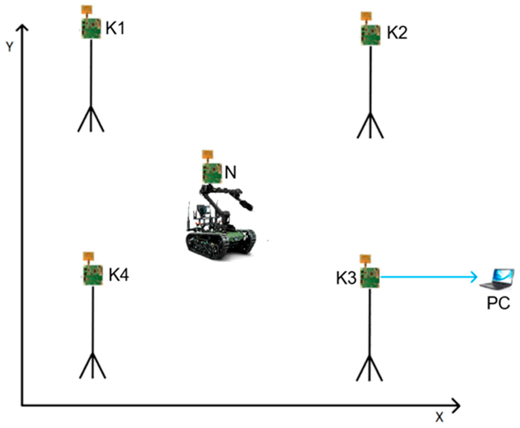
The proposed location system consists of four receivers, K1, K2, K3, and K4, arranged at the vertices of a square, constituting the system’s working field of 25 m × 25 m (Figure 1). The adopted field dimensions result from the assumptions made and an analysis of the hardware limitations listed in the manufacturer’s technical documentation [] and the author’s experimental research [,]. In the area between the receivers, move the transmitter (point N) on the UGV, which can move in the mentioned area. At least partial visibility between the receiver and the transmitter is required for the system to work properly [].
Figure 1. Schematic of the conceptual location system.
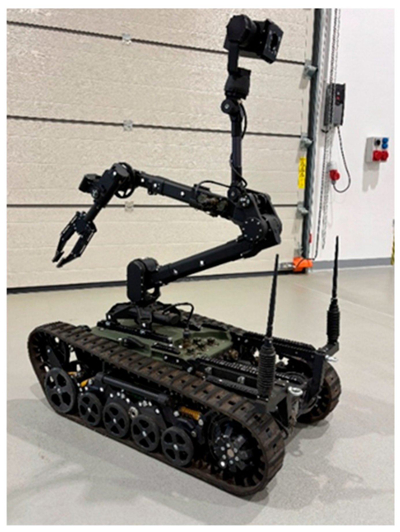
The PIAP Patrol mobile robot (Figure 2), which is on the equipment of the Military University of Technology in Warsaw, was adopted as the example of UGV for the conceptual layout (Figure 1). It is a medium-sized tracked UGV designed, among other things, to neutralize improvised explosive devices. It is equipped with a 6-degree-of-freedom manipulator with a gripper and camera, as well as wireless remote-control capabilities [].
Figure 2. PIAP Patrol robot.
The concept described here adopts Decawave’s TREK1000 UWB system, which meets the technology assumptions. The TREK1000 kit consists of five EVB1000 development boards []. Each has an STM32F105RCT6 microcontroller, which communicates with the DW1000 chip via an SPI interface. In addition, an Ultra-Wideband antenna and LCD are mounted in each module. The DW1000 chip supports six bands spanning 3.5 GHz to 6.5 GHz. It operates under the IEEE 802.15.4a-2011 standard [] and provides distance measurement accuracy of about 0.1 m []. UWB modules are programmable integrated circuits that can function as receivers or transmitters of the location system, as required. In terms of the number of modules, the minimum configuration for 2D localization includes four components: three receivers and one transmitter.
UWB TREK100 modules allow measuring the distance between the transmitter and the receiver. This value is updated at 10 Hz. The sampling frequency of the modules also depends on the frequency band. The distance-measurement principle implemented is TWR (Two-Way Ranging), a variant of the TOF (Time of Flight) method []. The TWR method relies on a two-way data exchange between the transmitter and receiver. As a result of transmitter-receiver communication, the time of flight is determined, and knowing the speed of propagation of electromagnetic waves in the air, it is possible to decide on the distance between the transmitter and a given receiver according to the relationship:
d = c t T 4  
where d—distance between transmitter and receiver; tT—total time of signal flight; and c—speed of light.
Systems based on the TWR communication method do not require time synchronization between UWB devices, which is an advantage of the solution [].
The operator of the UGV must be able to perform precise movements, so the speed of the UGV is often minimal. For this reason, it was assumed that 1 Hz is a sufficient frequency for determining the location. The solution must also be able to operate independently of the UGV’s traction system, e.g., wheels or tracks. For this reason, the proposed data processing scheme cannot be based on the UGV’s kinematic model (dynamic, if necessary). To minimize cost, the computational complexity of the system must be low. The mentioned requirements lead to the rejection of the use of the Kalman filter.
In order to determine an effective and low-cost data processing scheme that minimizes the number of necessary calculations and total errors of the location system, simulation studies were conducted, as described in Section 3 and Section 4.

3. Materials and Methods

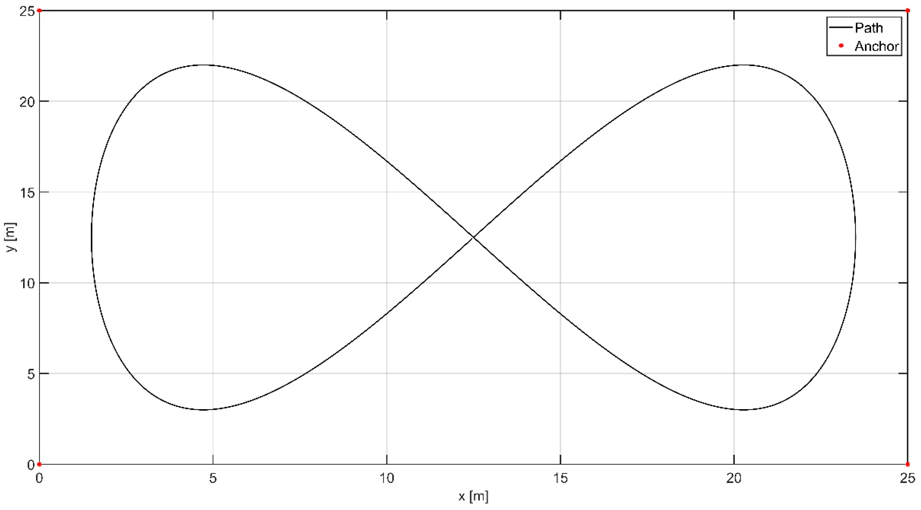
The MATLAB/Simulink R2023b software was selected as the simulation environment []. The following parametric equations were assumed to describe the position of the UGV in a two-dimensional x–y coordinate system (Figure 1):
x N = A x sin ω t + x 0  
y N = A y sin ω t cos ω t + y 0  
where Ax = 11 m, Ay = 19 m—geometric parameters of the motion curve; x0 = y0 = 12.5 m—curve position parameter; ω = 0.5 rad/s—lap frequency; and t—simulation time.
In turn, the coordinates of individual receivers were defined as:
  • K1 (x1 = 0 m, y1 = 25 m),
  • K2 (x2 = 25 m, y2 = 25 m),
  • K3 (x3 = 25 m, y3 = 0 m),
  • K4 (x4 = 0 m, y4 = 0 m).
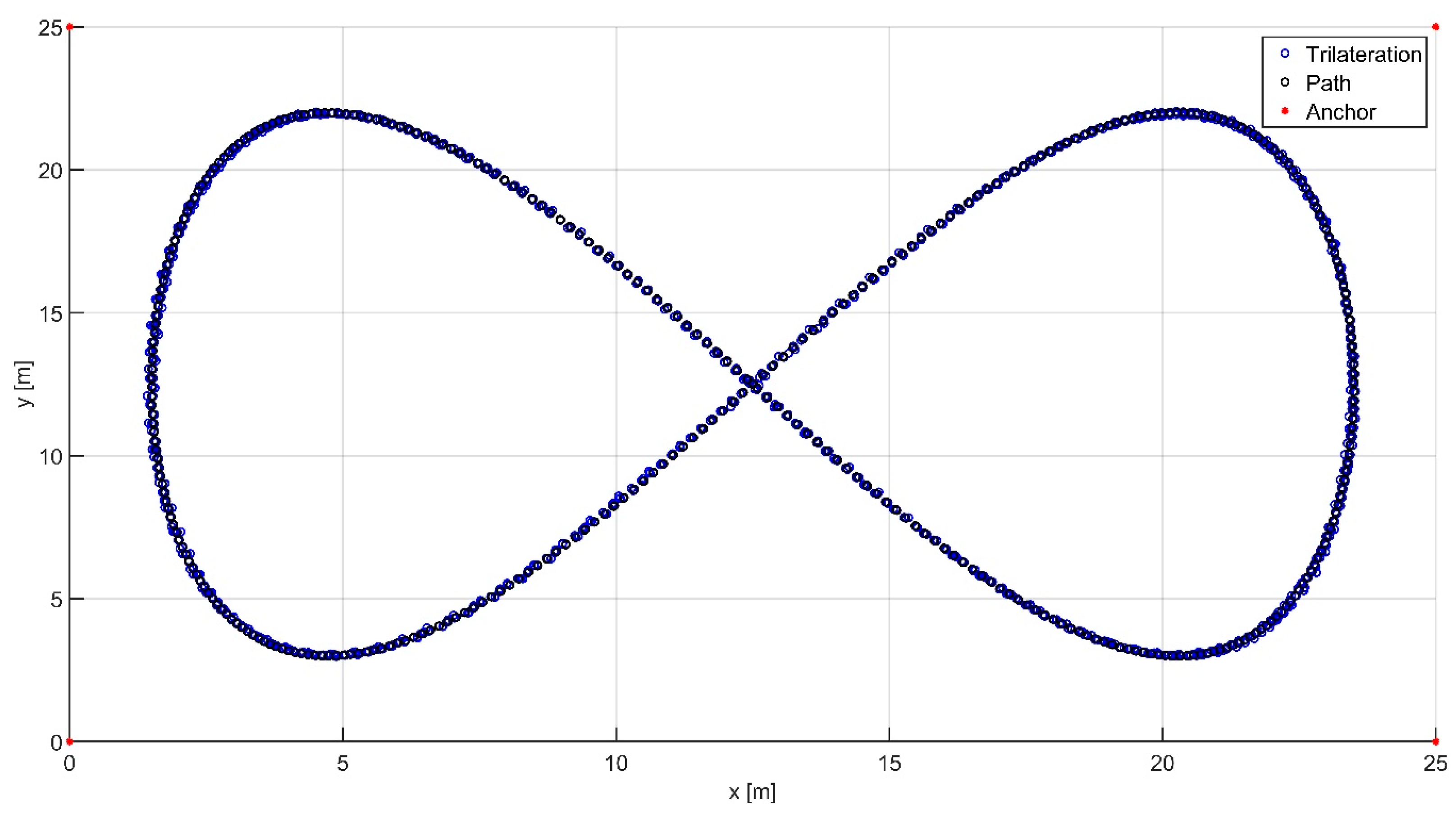
Figure 3 illustrates the placement of receivers (so-called anchors) at the corners of the workspace. The UGV trajectory was designed to remain entirely within the defined operational area.
Figure 3. Visualization of the UGV’s path and anchor placement.
The schematic of the conducted numerical simulation is shown in Figure 4. The process consists of four steps, the generation of distance measurements, pre-filtering (initial filtering), the localization algorithm (trilateration), and the final filtering of signals.
Figure 4. Schematic of data processing in the location system.
The presented data processing scheme yields the transmitter’s position coordinates (Figure 4). The first stage of the simulation involves determining distances from individual receivers to the transmitter and generating measurement noise. Next, initial filtering methods are applied to minimize the errors of the measured distances d1, d2, d3, and d4. To determine the transmitter’s location, a localization algorithm is required. Due to the requirement of low computational complexity, the trilateration method was chosen. Then, after determining the location (x, y) of the transmitter, signal filtering methods were applied again to minimize, in this case, the UGV’s localization errors. Additionally, in the case of filters, we assumed a maximum window value of 15.

3.1. Distance Measurement

After determining the coordinates of the receivers and the subsequent positions of the transmitter, the distances between the i-th receiver and transmitter can be described by the following relationships:
d 1 = ( x N x 1 ) 2 + ( y N y 1 ) 2
d 2 = ( x N x 2 ) 2 + ( y N y 2 ) 2
d 3 = ( x N x 3 ) 2 + ( y N y 3 ) 2
d 4 = ( x N x 4 ) 2 + ( y N y 4 ) 2
where di—distance from i-th receiver Ki (i = 1, 2, 3, 4) to transmitter; xN, yN—coordinates of transmitter in x–y coordinate system; and xi, yi—coordinates of i-th receiver Ki (i = 1, 2, 3, 4) in the adopted coordinate system x–y [].
Then, to reflect the real operation of UWB modules, measurement noise was introduced into the individual distance measurements according to the relationships:
d 1 Z = d 1 + z 1
d 2 Z = d 2 + z 2
d 3 Z = d 3 + z 3
d 4 Z = d 4 + z 4
where diz—distorted distances between transmitter and i-th receiver Ki (i = 1, 2, 3, 4); and zi—i-th receiver Ki (i = 1, 2, 3, 4) noise [].
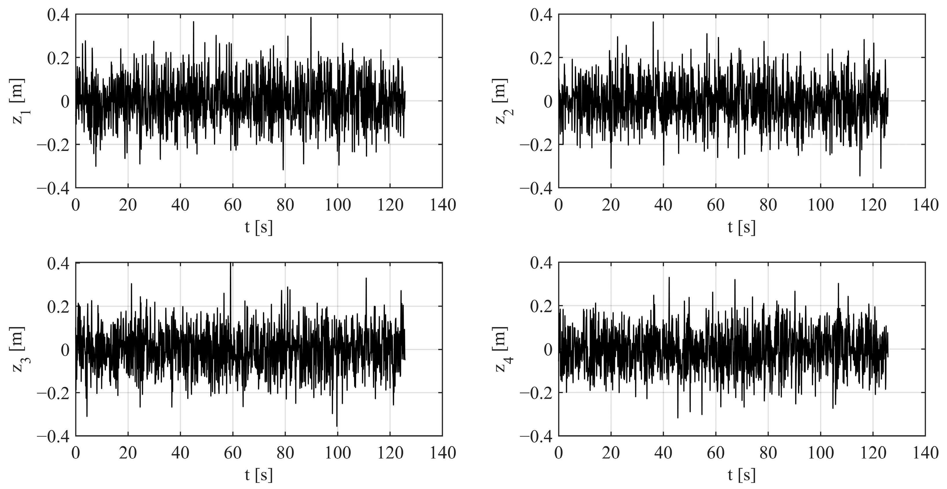
It was assumed that the measurement noise z1, z2, z3, and z4 are generated independently and follow a normal distribution with a standard deviation of 0.1 m [].

3.2. Initial Filtering

The second stage of data processing, according to Figure 4, is the pre-filtering of distance measurements diz (i = 1, 2, 3, 4). A study was conducted to determine the filtering method that minimizes the total errors of the location system. The main goal of initial filtering is to remove outliers and prepare the signal for further processing. The signal must not be distorted at this stage, which explains why the research was limited to only the following three filters:
  • Moving mean;
  • Hampel;
  • Median Filter.
To standardize the filter descriptions, all methods used will be discussed in Section 3.4.

3.3. Trilateration

Various localization algorithms can be implemented in UWB location systems, e.g., trilateration [], machine learning [], fuzzy logic [], optimization methods [,], and the Kalman filter []. The third stage of data processing, as shown in Figure 4, is localization using the trilateration algorithm, which is the basic algorithm used in TOF-based sensor-based location systems. All other algorithms mentioned above are much more computationally complex. Trilateration is characterized by a direct mathematical model, which is described later in the current subsection.
The relationship between the transmitter N and the i-th receiver Ki (i = 1, 2, 3, 4) can be written as follows:
d i 2 = x N x i 2 + y Z y i 2  
where di—the distance between the transmitter and the i-th receiver, Ki (i = 1, 2, 3, 4); xN, yN—the coordinates of the transmitter in the x–y system; and xi, yi—the coordinates of the i-th receiver Ki (i = 1, 2, 3, 4) in the x–y system.
The problem in determining the transmitter’s position is the presence of nonlinearity (quadratic dependence) in the coordinates xN and yN. For this purpose, a reference receiver needs to be adopted, such as receiver K1. Then, the differences between the reference receiver and the other receivers are determined:
d 1 2 d k 2 = 2 x N x k x 1 + 2 y N y k y 1 + e 1 e k  
where e k = x k 2 + y k 2 (k = 2, 3, 4).
After transformation, the relation (13) can be written in matrix form:
A = B X N  
where
A = d 1 2 d 2 2 + x 1 2 + y 1 2 x 2 2 y 2 2 d 1 2 d 3 2 + x 1 2 + y 1 2 x 3 2 y 3 2 d 1 2 d 4 2 + x 1 2 + y 1 2 x 4 2 y 4 2
B = 2 x 2 x 1 2 y 2 y 1 2 x 3 x 1 2 y 3 y 1 2 x 4 x 1 2 y 4 y 1
X N = x N y N
The position of the transmitter can be determined, for example, using the least squares method:
X N = ( B T B ) 1 B T A
The presented mathematical relationships enable the simulation of UGV localization.

3.4. Final Filtering

The fourth stage of data processing, as shown in Figure 4, is the final filtering of the localization results obtained using the trilateration algorithm. The localization coordinates of the transmitter were again subjected to the filtering process in order to minimize the localization errors in this case.
A study was conducted to determine the optimal filtering method for minimizing the total location system errors. The following filtering methods were adopted for the study:
  • Moving mean;
  • LOESS;
  • RLOESS;
  • Savitzky–Golay;
  • Hampel;
  • Median Filter.
The first evaluated filtering technique was the moving mean filter. For this filter, the parameter under evaluation is the window size. The moving mean filter is a linear time-domain filter. It is used to smooth time waveforms with no discernible trend [].
The following two filtering methods are LOESS (Locally Estimated Scatterplot Smoothing) and RLOESS (Robust Locally Estimated Scatterplot Smoothing), which operate similarly [,]. They perform the regression using a weighted linear least-squares method and a second-order polynomial model. These methods combine the versatility of linear regression and the flexibility of nonlinear regression. The main parameter for both functions is the span value.
The Savitzky–Golay filter is a digital filter for smoothing data without distorting the signal’s trend [,,]. This is accomplished by fitting successive subsets of adjacent data points with a low-degree polynomial using least-squares. The process requires two parameters: the degree of the polynomial and the window size.
The Hampel filter is a nonlinear signal filtering method primarily used to detect and eliminate outliers in time series []. It operates using a moving window to compute the median and the median absolute deviation (MAD). Detected outliers are replaced with the median computed within a local window.
Median filter is, in turn, the last-mentioned filter in the analysis. It is a simple filter that selects the middle value of an ascending sequence of values, with the number of elements equal to the window length. In addition, it is characterized by resistance to impulsive noise measurement [].

3.5. Quality Indicators

The Sum of Squared Errors (SSE), Mean Squared Error (MSE), and Mean Absolute Error (MAE) indicators were adopted to evaluate the quality of each filtering method. The SSE indicator is the value of the sum of the squares of the difference between predicted and actual values according to the relationship:
S S E = i = 1 n x i x ^ i 2
where x i —the i-th observed value; and x ^ i —the i-th predicted value (i = 1, …, n) [].
In turn, the MSE indicator represents the average sum of squares of the difference between predicted and actual values:
M S E = i = 1 n x i x ^ i 2 n
where n—the number of observations [].
The last indicator accepted for evaluation is MAE, which measures the average absolute difference between predicted and actual values:
M A E = i = 1 n y i y ^ i n
Both SSE and MSE are indicators based on quadratic (nonlinear) measures, while MAE is a quality indicator based on a linear measure [].

4. Results

The adopted noise waveforms reflecting the actual interference occurring in UWB modules had a normal distribution with a standard deviation of 0.1 m (Figure 5).
Figure 5. Simulated noises for distances d1–d4.
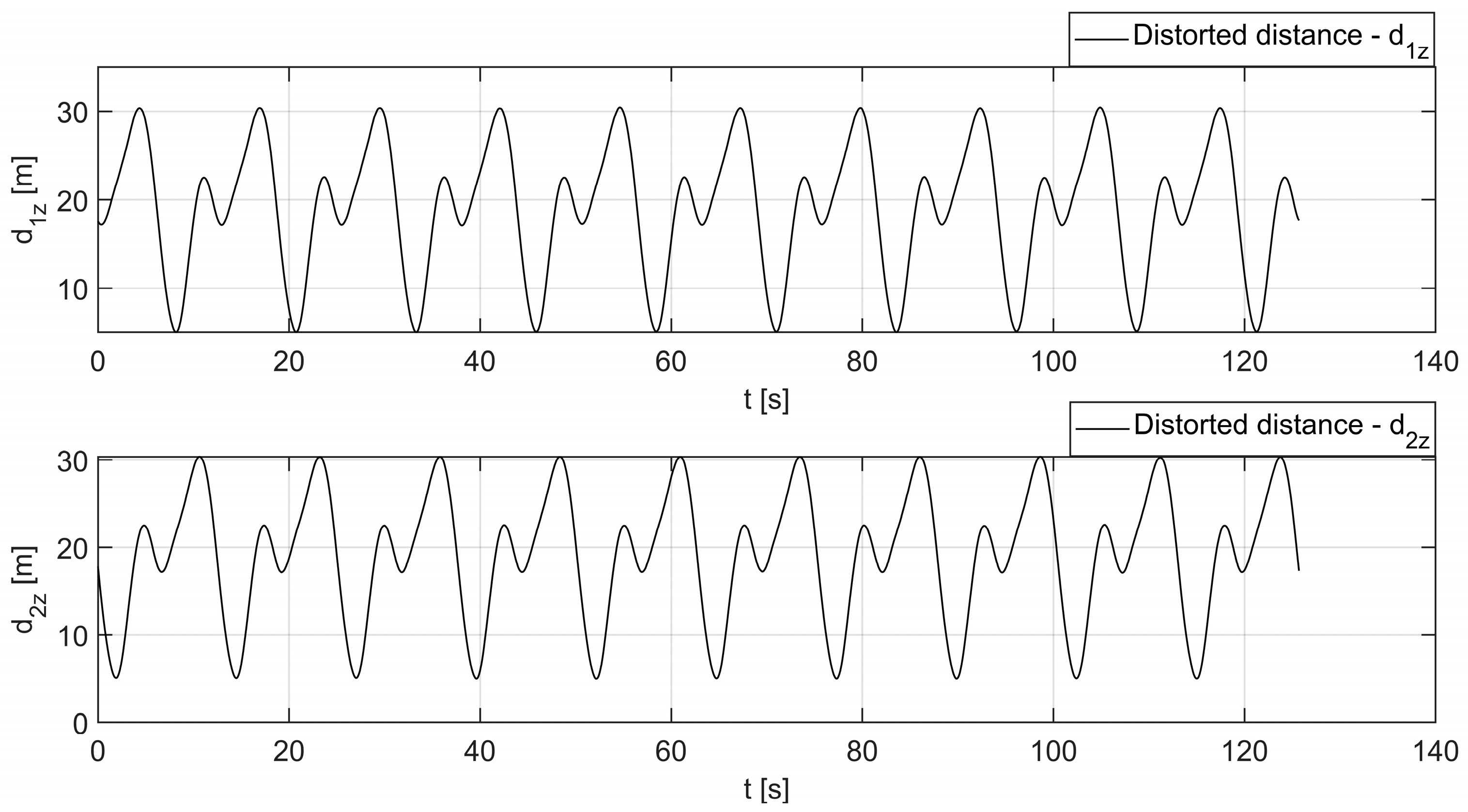
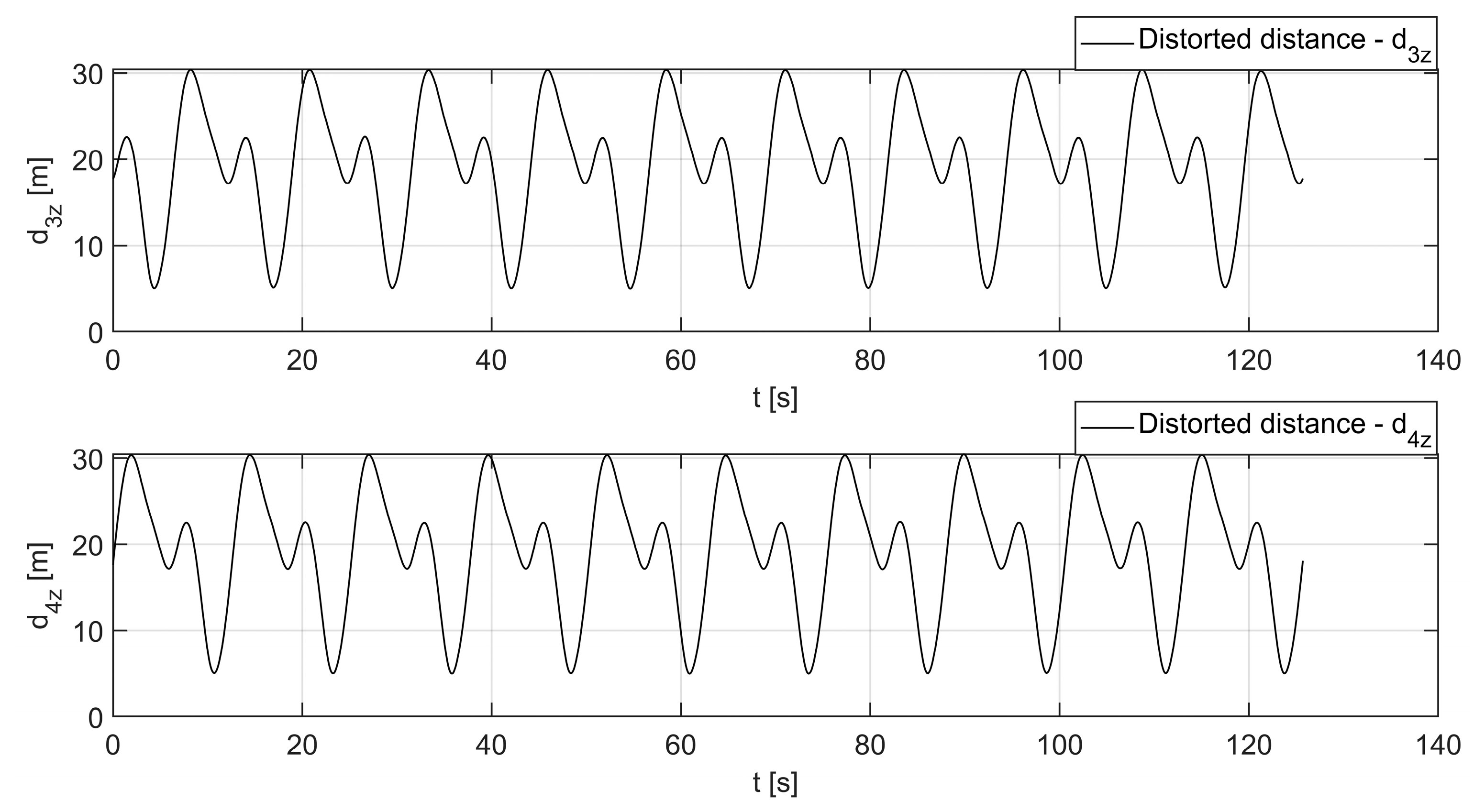
Figure 6 and Figure 7 show a comparison of the distorted distances d1z–d4z. Because the noise values are relatively small (−0.3 m to 0.3 m) compared to the reference distance measurements (ranging from 5 m to 30 m), the corresponding waveforms visually overlap.
Figure 6. Time courses of the distorted distances from the transmitter to the receivers K1 and K2.
Figure 7. Time courses of the distorted distances from the transmitter to the receivers K3 and K4.
In addition, it was assumed that the UGV’s movement lasted about 126 s (Figure 6 and Figure 7), which translates into completing ten full laps of the motion path shown in Figure 3.
The results for the SSE, MSE, and MAE quality indicators without filtering methods are presented in Table 1 and serve as the baseline for subsequent comparisons.
Table 1. Results for the location system’s performance without filtering.
In turn, Table 2 presents the results of the quality indicators for the initial signal filtering.
Table 2. Results of initial filtering methods.
The primary goal of the initial filtering was to minimize outliers. It was observed that significant smoothing of the distance measurements hinders subsequent final filtering. Therefore, although the best-quality indicator values were obtained using the moving mean method (with a window size of 3), a one-dimensional median filter with the same window size was selected for this stage of signal processing. This is a nonlinear method that allows the reduction in individual outliers without significant distortion of the input signal.
In turn, Table 3 presents the results of quality indicators in the case of final signal filtering.
Table 3. Results of final filtering methods.
The Savitzky–Golay filter proved to be the best at minimizing the quality indicators —SSE, MSE, and MAE—when configured with a window size of 15 and a polynomial degree of 3. In the Savitzky–Golay method, a tendency for indicator values to decrease with increasing window size was observed. In the case of other methods, on the other hand, a trend of increasing indicator values with increasing parameter values was observed. The moving mean, Hampel, and median filters achieve the best results with a window size of 3, LOESS with a span of 0.02, and RLOESS with a span of 0.01.
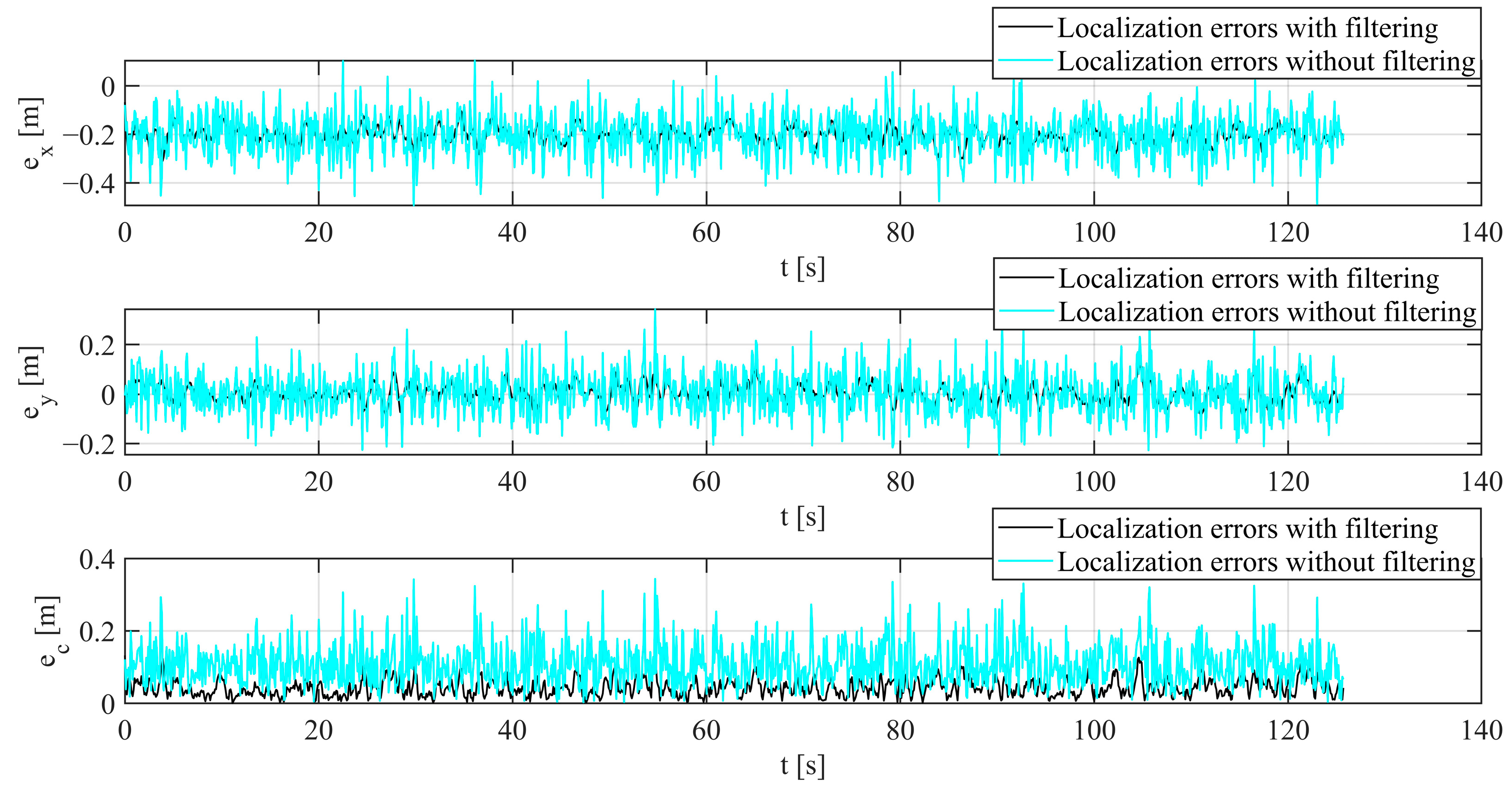
The performed simulations enabled numerical determination of localization errors, using the proposed signal processing scheme (Figure 4). In turn, Figure 8 shows the localization errors along the x- and y-axes of the coordinate system, as well as the total errors, for scenarios without filtering and with the proposed filtering methods.
Figure 8. Localization errors on the x- and y-axes of the coordinate system and the total localization error.
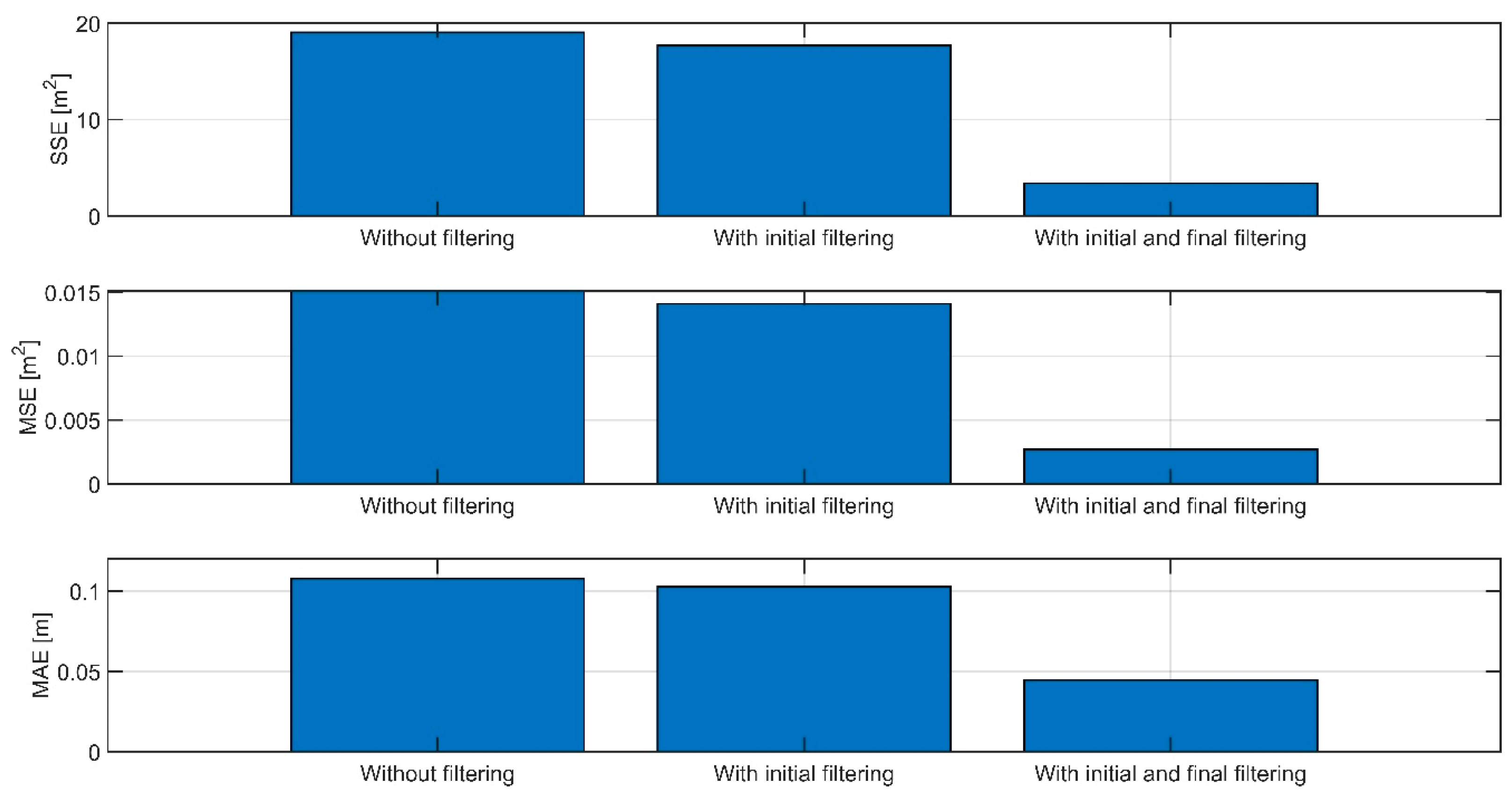
As shown in Figure 8, the filtering methods used significantly reduced localization errors. The total localization error, excluding the simulation’s beginning and end, did not exceed 0.1 m, while the average total error was approximately 0.045 m. In addition, the applied filtering, both initial filtering and a combination of initial and final filtering, significantly reduced the adopted quality indicators, as shown in Figure 9.
Figure 9. Results of SSE, MSE, and MAE quality indicators depending on the filtering method used.
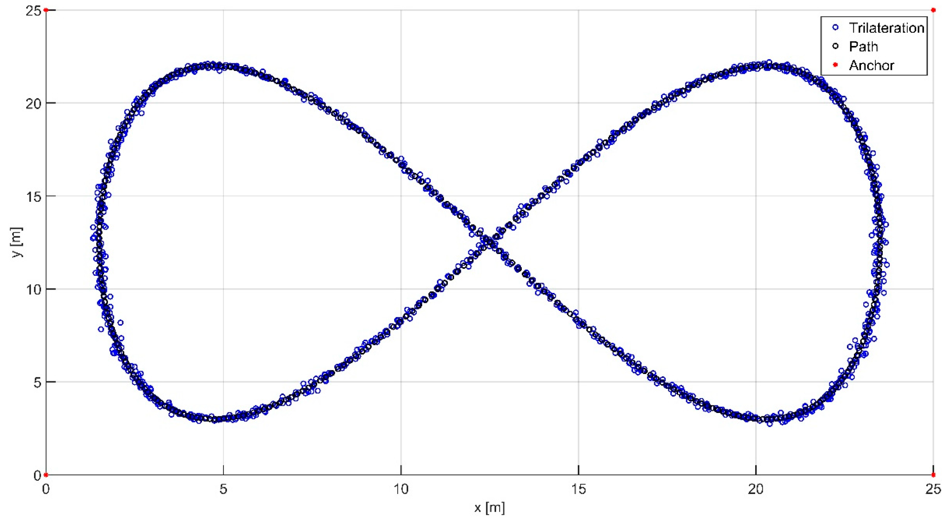
Analysis of the data shown in Figure 9 indicated that applying initial filtering alone reduced the quality indicators SSE and MSE by about 7% and MAE by about 5%. In contrast, the combination of initial and final filtering showed a significant improvement in quality indicators: SSE and MSE by about 82%, and MAE by about 59%. The nonlinear quality indicators (quadratic) in both cases reached higher values than the linear MAE index, suggesting that the applied filtering significantly minimizes outliers and errors with large amplitudes. Next, Figure 10 and Figure 11 compare the UGV motion trajectories determined without filtering with those obtained using the filtering methods proposed in the paper.
Figure 10. Localization results without signal filtering.
Figure 11. Localization results with the initial and final filtering applied.
The obtained motion waveforms (Figure 10 and Figure 11) are characterized by a high degree of similarity to the set motion path.

5. Discussion

For a low-cost location system, the best solution would be to implement simpler filter variants that provide more stable, faster signal filtering to minimize system operation delays.
In the case of initial filtering, it was observed that more complex filters, such as Savitzky–Golay, provide better smoothing of noisy distance measurements, but ultimately this leads to distortion of the UGV’s x and y coordinates, increased localization errors, and a distorted final UGV movement trajectory. For this reason, at this stage of signal processing, it was decided to select a median filter with a minimum window size of three.
The Savitzky–Golay filter is intended to be used with the last data in the window for real-time processing. As expected, filters with greater computational complexity and more complex mathematical models, such as the Savitzky–Golay filter, achieved lower localization errors. A characteristic feature of this filter is that the quality indicators (SSE, MSE, MAE) decrease as the filter window length increases. This is because increasing the window length also increases the number of measurements used to determine the fitting polynomial coefficients. In this study, a maximum window length of 15 was assumed.
The simulation studies ignored the impact of environmental factors on UWB module operation, which can result in temporary distance measurement errors and, consequently, a lack of UGV location. It is worth noting that one advantage of Savitzky–Golay filters is their high filtering efficiency in the presence of occasional signal losses, which is a possible direction for further research.

6. Conclusions

Simulation studies play a significant role in the development of location systems, enabling the testing of various signal processing techniques, including positioning algorithms and filtering methods, before real-world implementation.
Research has shown that selecting appropriate signal filtering methods through preliminary numerical analysis reduces localization errors.
The direction of further research is the practical construction of the described location system, performing experimental tests of the system (LOS conditions), and comparing the obtained results with the simulation results.

Author Contributions

Conceptualization, Ł.R., M.P. and K.C.; methodology, Ł.R., T.M. and K.C.; software, Ł.R.; validation, Ł.R., K.C., M.P. and T.M.; formal analysis, Ł.R., M.P. and K.C.; investigation, Ł.R., T.M. and M.P.; resources, Ł.R., M.P., K.C. and T.M.; data curation, Ł.R.; writing—original draft preparation, Ł.R.; writing—review and editing, Ł.R., M.P., K.C. and T.M.; visualization, Ł.R., M.P. and K.C.; supervision, Ł.R. and T.M.; project administration, T.M.; funding acquisition, Ł.R. All authors have read and agreed to the published version of the manuscript.

Funding

This work was financed by the Military University of Technology under the research project UGB 22-017/2025.

Institutional Review Board Statement

Not applicable.

Data Availability Statement

The data presented in this study are available on request from the corresponding author.

Conflicts of Interest

The authors declare no conflicts of interest.

Abbreviations

The following abbreviations are used in this manuscript:
DMCDeterministic Multipath Component
EGNOSEuropean Geostationary Navigation Overlay Service
EKFExtended Kalman Filter
FIRFinite Impulse Response
GNSSGlobal Navigation Satellite Systems
IIR Infinite Impulse Response
IMUInertial Measurement Unit
LIDARLight Detection and Ranging
LOESSLocally Estimated Scatterplot Smoothing
LOSLine of Sight
MADMedian Absolute Deviation
MAEMean Absolute Error
MSEMean Squared Error
NLOSNon-Line of Sight
RGB-D Red Green Blue—Depth
RLOESSRobust Locally Estimated Scatterplot Smoothing
RMSRoot Mean Square
RSSI Received Signal Strength Indicator
RTKReal-Time Kinematic
SBASSatellite-Based Augmentation System
SSESum Of Squares Error
TDOATime Difference of Arrival
TOATime of Arrival
TOFTime of Flight
TWRTwo-Way Ranging
UGVUnmanned Ground Vehicle
UKFUnscented Kalman Filter
UWBUltra-Wideband
VBAKFVariational Bayesian Adaptive Kalman Filter

References

  1. Rykała, Ł.; Typiak, A.; Typiak, R. Research on Developing an Outdoor Location System Based on the Ultra-Wideband Technology. Sensors 2020, 20, 6171. [Google Scholar] [CrossRef] [PubMed]
  2. Bartnicki, A. Demand for remote control station of unmanned platform in terms of conducting missions aiming at reducing threat caused by uncontrolled leak of dangerous substances. Logistyka 2012, 3, 61–68. (In Polish) [Google Scholar]
  3. Typiak, A.; Typiak, R. Researching different control strategies for a manipulator arm in a teleoperated configuration. Logistyka 2010, 2, 1–14. (In Polish) [Google Scholar]
  4. Typiak, A. Sterowanie Mobilnymi Maszynami Inżynieryjnymi w Układzie Teleoperacji; Wojskowa Akademia Techniczna: Warsaw, Poland, 2013. (In Polish) [Google Scholar]
  5. Januszewski, J. GPS Satellite Systems, Galileo and Others; PWN: Warsaw, Poland, 2007. [Google Scholar]
  6. Narkiewicz, J. GPS and Other Satellite Navigation Systems; WKiŁ: Warsaw, Poland, 2007. [Google Scholar]
  7. Blesing, C.; Finke, J.; Hoose, S.; Schweigert, A.; Stenzel, J. Accuracy evaluation of a low-cost differential global positioning system for mobile robotics. In Proceedings of the 2023 IEEE SENSORS, Vienna, Austria, 29 October–1 November 2023; pp. 1–4. [Google Scholar]
  8. Takanose, A.; Kondo, K.; Hoda, Y.; Meguro, J.; Takeda, K. Localization system for vehicle navigation based on GNSS/IMU using time-series optimization with road gradient constraint. J. Robot. Mechatron. 2023, 35, 387–397. [Google Scholar] [CrossRef]
  9. Xuan, J.; Zhu, T.; Peng, G.; Sun, F.; Dong, D. A Review on the Inertial Measurement Unit Array of Microelectromechanical Systems. Sensors 2024, 24, 7140. [Google Scholar] [CrossRef]
  10. Cramer, M.; Cramer, J.; De Schepper, D.; Aerts, P.; Kellens, K.; Demeester, E. Benchmarking low-cost inertial measurement units for indoor localisation and navigation of AGVs. Procedia CIRP 2019, 86, 204–209. [Google Scholar] [CrossRef]
  11. Vilau, R.; Voicu, D.; Stoica, R.M.; Ciobotaru, T.; Rykała, M.; Rykała, Ł. Investigating Vibration Transmission in Cargo Containers During Heavy-Duty Off-Road Transport. Adv. Sci. Technol. Res. J. 2024, 18, 312–328. [Google Scholar] [CrossRef]
  12. Min, K.I.; Jeong, J.B.; Oh, J.S.; Kim, J.H. Research of vision system for perception in UGV. In Proceedings of the 2013 13th International Conference on Control, Automation and Systems (ICCAS 2013), Gwangju, Republic of Korea, 20–23 October 2023; pp. 1351–1355. [Google Scholar]
  13. Nowakowski, M. Operational Environment Impact on Sensor Capabilities in Special Purpose Unmanned Ground Vehicles. In Proceedings of the 2024 21st International Conference on Mechatronics-Mechatronika (ME), Brno, Czech Republic, 4–6 December 2024; IEEE: New York, NY, USA, 2024; pp. 1–5. [Google Scholar]
  14. Kiczek, B.; Batsch, M. Exploration of Unsupervised Deep Learning-Based Gear Fault Detection for Wind Turbine Gearboxes. Energies 2025, 18, 3630. [Google Scholar] [CrossRef]
  15. Icagic, S.D.; Kvascev, G.S. A Smart Alcoholmeter Sensor Based on Deep Learning Visual Perception. Sensors 2022, 22, 7394. [Google Scholar] [CrossRef]
  16. Batsch, M.; Nowak, D.; Wydrzyński, D.; Kochmański, Ł. Vision-based control of small educational parallel selective compliance assembly robot arm robot. Adv. Sci. Technol. Res. J. 2025, 19, 440–457. [Google Scholar] [CrossRef]
  17. Kim, T.; Lim, S.; Shin, G.; Sim, G.; Yun, D. An open-source low-cost mobile robot system with an RGB-D camera and efficient real-time navigation algorithm. IEEE Access 2022, 10, 127871–127881. [Google Scholar] [CrossRef]
  18. Będkowski, J.; Pełka, M. Affordable Robotic Mobile Mapping System Based on Lidar with Additional Rotating Planar Reflector. Sensors 2023, 23, 1551. [Google Scholar] [CrossRef] [PubMed]
  19. Nowakowski, M.; Kurylo, J.; Dang, P.H. Camera Based AI Models Used with LiDAR Data for Improvement of Detected Object Parameters. In Modelling and Simulation for Autonomous Systems; Springer Nature: Cham, Switzerland, 2023; pp. 287–301. [Google Scholar]
  20. Liu, Y.; Wang, C.; Wu, H.; Wei, Y.; Ren, M.; Zhao, C. Improved LiDAR Localization Method for Mobile Robots Based on Multi-Sensing. Remote Sens. 2022, 14, 6133. [Google Scholar] [CrossRef]
  21. Kim, J.; Park, B.-j.; Kim, J. Empirical Analysis of Autonomous Vehicle’s LiDAR Detection Performance Degradation for Actual Road Driving in Rain and Fog. Sensors 2023, 23, 2972. [Google Scholar] [CrossRef]
  22. Chen, P.; Zhao, X.; Zeng, L.; Liu, L.; Liu, S.; Sun, L.; Li, Z.; Chen, H.; Liu, G.; Qiao, Z.; et al. A Review of Research on SLAM Technology Based on the Fusion of LiDAR and Vision. Sensors 2025, 25, 1447. [Google Scholar] [CrossRef]
  23. Sukop, M.; Grytsiv, M.; Jánoš, R.; Semjon, J. Simple Ultrasonic-Based Localization System for Mobile Robots. Appl. Sci. 2024, 14, 3625. [Google Scholar] [CrossRef]
  24. Juan, C.-W.; Hu, J.-S. Object Localization and Tracking System Using Multiple Ultrasonic Sensors with Newton–Raphson Optimization and Kalman Filtering Techniques. Appl. Sci. 2021, 11, 11243. [Google Scholar] [CrossRef]
  25. Tzafestas, S.G. Introduction to Mobile Robot Control; Elsevier: Amsterdam, The Netherlands, 2013. [Google Scholar]
  26. Leitch, S.G.; Ahmed, Q.Z.; Abbas, W.B.; Hafeez, M.; Laziridis, P.I.; Sureephong, P.; Alade, T. On Indoor Localization Using WiFi, BLE, UWB, and IMU Technologies. Sensors 2023, 23, 8598. [Google Scholar] [CrossRef] [PubMed]
  27. Rykała, Ł.; Typiak, A.; Typiak, R.; Rykała, M. Application of Smoothing Spline in Determining the Unmanned Ground Vehicles Route Based on Ultra-Wideband Distance Measurements. Sensors 2022, 22, 8334. [Google Scholar] [CrossRef]
  28. UWB VS Bluetooth: Which Offers Better Indoor Positioning Accuracy. Available online: https://www.mokosmart.com/uwb-vs-bluetooth-indoor-positioning-guide/ (accessed on 8 November 2025).
  29. Alarifi, A.; Al-Salman, A.; Alsaleh, M.; Alnafessah, A.; Al-Hadhrami, S.; Al-Ammar, M.A.; Al-Khalifa, H.S. Ultra Wideband Indoor Positioning Technologies: Analysis and Recent Advances. Sensors 2016, 16, 707. [Google Scholar] [CrossRef]
  30. Dong, M.; Qi, Y.; Wang, X.; Liu, Y. A non-line-of-sight mitigation method for indoor ultra-wideband localization with multiple walls. IEEE Trans. Ind. Inform. 2022, 19, 8183–8195. [Google Scholar] [CrossRef]
  31. Che, F.; Ahmed, Q.Z.; Khan, F.A.; Lazaridis, P.I. Anomaly detection based on generalized Gaussian distribution approach for ultra-wideband (uwb) indoor positioning system. In Proceedings of the 2021 26th International Conference on Automation and Computing (ICAC), Portsmouth, UK, 2–4 September 2021; IEEE: New York, NY, USA, 2021; pp. 1–5. [Google Scholar]
  32. Majeed, A.F.; Arsat, R.; Baharudin, M.A.; Latiff, N.M.A.A.; Albaidhani, A. Accurate multiclass NLOS channels identification in UWB indoor positioning system-based deep neural network. IEEE Access 2024, 12, 179431–179448. [Google Scholar] [CrossRef]
  33. Zhang, Z.; Zhao, R.; Zhang, H.; Zhu, W.; Jia, P.; Li, C.; Ma, Y. Variable-Weighted Error Propagation Model of a Ultra-Wide-Band Indoor Positioning System in an Intelligent Manufacturing Lab. Appl. Sci. 2023, 13, 8400. [Google Scholar] [CrossRef]
  34. Sidorenko, J.; Schatz, V.; Scherer-Negenborn, N.; Arens, M.; Hugentobler, U. Decawave UWB Clock Drift Correction and Power Self-Calibration. Sensors 2019, 19, 2942. [Google Scholar] [CrossRef]
  35. Yang, H.; Wang, Y.; Seow, C.K.; Li, Z.; Sun, M.; De Cock, C.; Plets, D. NLOS Identification and Ranging Trustworthiness for Indoor Positioning with LLM-based UWB-IMU Fusion. IEEE Trans. Instrum. Meas. 2025, 74, 8509417. [Google Scholar] [CrossRef]
  36. Ali, R.; Liu, R.; Nayyar, A.; Qureshi, B.; Cao, Z. Tightly coupling fusion of UWB ranging and IMU pedestrian dead reckoning for indoor localization. IEEE Access 2021, 9, 164206–164222. [Google Scholar] [CrossRef]
  37. Jiang, P.; Hu, C.; Wang, T.; Lv, K.; Guo, T.; Jiang, J.; Hu, W. Research on a Visual/Ultra-Wideband Tightly Coupled Fusion Localization Algorithm. Sensors 2024, 24, 1710. [Google Scholar] [CrossRef]
  38. Huang, Y.; Cao, B.; Wang, A. Design a novel algorithm for enhancing UWB positioning accuracy in GPS denied environments. Sci. Rep. 2024, 14, 23895. [Google Scholar] [CrossRef]
  39. Vitanov, R.I.; Nikolov, D.N. A state-of-the-art review of ultra-wideband localization. In Proceedings of the 2022 57th International Scientific Conference on Information, Communication and Energy Systems and Technologies (ICEST), Ohrid, North Macedonia, 16–18 June 2022; pp. 1–4. [Google Scholar]
  40. Trek1000 User Manual. (n.d.). Available online: https://datasheet.octopart.com/TREK1000-Decawave-datasheet-98959800.pdf (accessed on 13 October 2025).
  41. Malon, K.; Łopatka, J.; Rykała, Ł.; Łopatka, M. Accuracy Analysis of UWB Based Tracking System for Unmanned Ground Vehicles. In Proceedings of the 2018 New Trends in Signal Processing (NTSP), Demänovská Dolina, Slovakia, 10–12 October 2018; pp. 1–7. [Google Scholar]
  42. PIAP Patrol. Available online: https://piap.lukasiewicz.gov.pl/2020/05/19/nowy-robot-mobilny-piap-patrol/ (accessed on 13 October 2025).
  43. IEEE Std 802.15.4a-2011; Standard for Local and Metropolitan Area Networks—Part 15.4: Low-Rate Wireless Personal Area Networks (LR-WPANs). IEEE: New York, NY, USA, 2011.
  44. Lian Sang, C.; Adams, M.; Hörmann, T.; Hesse, M.; Porrmann, M.; Rückert, U. Numerical and Experimental Evaluation of Error Estimation for Two-Way Ranging Methods. Sensors 2019, 19, 616. [Google Scholar] [CrossRef]
  45. MATLAB and Simulink. (n.d.). MATLAB and Simulink Documentation. Available online: https://www.mathworks.com/ (accessed on 13 October 2025).
  46. Rykała, Ł.; Przybysz, M.; Cieślik, K.; Krogul, P.; Typiak, R.; Typiak, A. Research on selected location algorithms for the UGV operating in a follow-me scenario based on ultra-wideband positioning system. Adv. Sci. Technol. Res. J. 2025, 19, 1–14. [Google Scholar] [CrossRef]
  47. Gnaś, D.; Majerek, D.; Styła, M.; Adamkiewicz, P.; Skowron, S.; Sak-Skowron, M.; Ivashko, O.; Stokłosa, J.; Pietrzyk, R. Enhanced Indoor Positioning System Using Ultra-Wideband Technology and Machine Learning Algorithms for Energy-Efficient Warehouse Management. Energies 2024, 17, 4125. [Google Scholar] [CrossRef]
  48. Wu, J.; Zhang, Z.; Zhang, S.; Kuang, Z.; Zhang, L. UWB Positioning Algorithm Based on Fuzzy Inference and Adaptive Anti-NLOS Kalman Filtering. Appl. Sci. 2022, 12, 6183. [Google Scholar] [CrossRef]
  49. Xie, C.; Fang, X.; Yang, X. Improved Kalman Filtering Algorithm Based on Levenberg–Marquardt Algorithm in Ultra-Wideband Indoor Positioning. Sensors 2024, 24, 7213. [Google Scholar] [CrossRef] [PubMed]
  50. Lyandres, V.; Briskin, S. On an approach to moving-average filtering. Signal Process. 1993, 34, 163–178. [Google Scholar] [CrossRef]
  51. Gijbels, I.; Prosdocimi, I. Loess. Wiley Interdiscip. Rev. Comput. Stat. 2010, 2, 590–599. [Google Scholar] [CrossRef]
  52. Eubank, R.L. Nonparametric Regression and Spline Smoothing; CRC Press: Boca Raton, FL, USA, 1999. [Google Scholar]
  53. Dombi, J.; Dineva, A. Adaptive Savitzky-Golay filtering and its applications. Int. J. Adv. Intell. Paradig. 2020, 16, 145–156. [Google Scholar] [CrossRef]
  54. Kordestani, H.; Zhang, C. Direct Use of the Savitzky–Golay Filter to Develop an Output-Only Trend Line-Based Damage Detection Method. Sensors 2020, 20, 1983. [Google Scholar] [CrossRef]
  55. Borhan, N.; Saleh, I.; Rahiman, W. Comparative Analysis of Filtering Techniques for AGV Indoor Localization with Ultra-Wideband Technology. Pertanika J. Sci. Technol. 2024, 32, 2151–2164. [Google Scholar] [CrossRef]
  56. Roos-Hoefgeest Toribio, M.; Garnung Menéndez, A.; Roos-Hoefgeest Toribio, S.; Álvarez García, I. A Novel Approach to Speed Up Hampel Filter for Outlier Detection. Sensors 2025, 25, 3319. [Google Scholar] [CrossRef]
  57. Osowski, S. Metody i Narzędzia Eksploracji Danych; Wydawnictwo BTC: Warsaw, Poland, 2013. (In Polish) [Google Scholar]
Disclaimer/Publisher’s Note: The statements, opinions and data contained in all publications are solely those of the individual author(s) and contributor(s) and not of MDPI and/or the editor(s). MDPI and/or the editor(s) disclaim responsibility for any injury to people or property resulting from any ideas, methods, instructions or products referred to in the content.

Article Metrics

Citations

Article Access Statistics

Multiple requests from the same IP address are counted as one view.