1. Introduction
With the continuous development of China‘s new power system with renewable energy as the main body, the installed capacity of clean-energy-generating units represented by wind power and photoelectricity is rising steadily. However, new energy power generation has randomness and uncertainty. Wind power generation and photovoltaic power generation are not only unevenly distributed in the region, but also the time distribution of their output is constantly fluctuating. The load distribution of the regional power grid often does not match the total installed capacity of the new energy units, which leads to the lack of new energy consumption capacity in the weak load area, and the high power generation capacity and power generation cost of the new energy conventional units in the load-intensive area, resulting in uneven power flow distribution between the regional power grids [
1,
2]. The interconnection of power systems is helpful to realize the complementarity of energy resources in multiple regions in time and space. It is of great significance to carry out the research on flexible mutual assistance of regional power grids to improve the power generation of new energy in power systems, reduce the curtailment of new energy and curtailment rate, and realize the goal of “double rise and double drop“ of new energy consumption.
As a new energy system integrating various functions such as collection, transmission, storage and distribution of electric energy, distribution network has great interconnection potential. However, with the high proportion of distributed energy access and the diversification of user load, the problems of bidirectional power flow, voltage over-limit and unbalanced feeder load in distribution network will be more prominent, which will further lead to the increase in system operation loss, the decrease in distributed energy consumption capacity and the overload of distribution equipment, seriously affecting the economic operation of distribution network [
3,
4,
5]. The voltage control of distribution network can be realized by on-load tap changer (OLTC), but the adjustment ability of OLTC is limited and the accuracy is insufficient [
6]. The traditional distribution network usually uses mechanical switches to connect adjacent feeders. This structure will further deteriorate the power imbalance problem in the distribution station area. The direct ring network between feeders will also bring problems such as circulating power and electromagnetic ring network [
7].
In recent years, the development of power electronics technology has provided an opportunity to solve the above problems. Foreign scholars have proposed a variety of flexible interconnection concepts, such as flexible looped network controller (FLNC) [
8], smart power/information exchange station (SPIES) [
9], Soft Open Point (SOP) [
10] and energy router (ER) [
11]. However, existing technologies like FLNC and SOP face challenges in station area–level interconnection scenarios. For instance, while SOPs offer precise power control, their implementation in multi-terminal low-voltage networks often involves high costs and complex coordination, limiting widespread adoption [
12]. Similarly, the centralized control architecture of conventional FLNCs may lack the flexibility required for dynamic power exchange in distributed renewable-rich environments. These limitations underscore the necessity for a more adaptive and cost-effective solution like the DPFC proposed in this work, which combines distributed deployment with flexible power flow control. Distributed power flow controller is a kind of power electronic device with power flow control function. It can replace mechanical switch as a flexible interconnection device because of its strong controllability and high flexibility [
13]. The distributed power flow controller can be installed on the line or tower in a distributed manner and constructed in batches according to the requirements of power grid planning, which has better flexibility and economy than the centralized topology.
At present, the research on flexible interconnection of distribution networks has less consideration on the phenomenon of light and heavy load of transformers in the station area and the economic operation of transformers. Long-term light and heavy load operation of transformers will bring hidden dangers to the safe operation of distribution networks. Therefore, this paper proposes a flexible mutual-aid control strategy between interconnected regional power grids based on distributed power flow controllers. Taking the distribution network of the station area as an example, the distributed power flow control is used as a flexible interconnection device to realize the interconnection of low-voltage stations, mutual backup and flexible mutual assistance. The control strategy proposed in this paper can reduce the transformer capacity configuration in the station area, with an expected reduction of 15–25% compared to conventional design methods, reduce the capacity increase pressure of the distribution network, improve the power flow control ability of the distribution network by approximately 30–40% and the power quality of the terminal distribution users, and finally, based on the PSCAD/EMTDC simulation platform, verify the feasibility of the control strategy.
2. System Structure and Main Problems
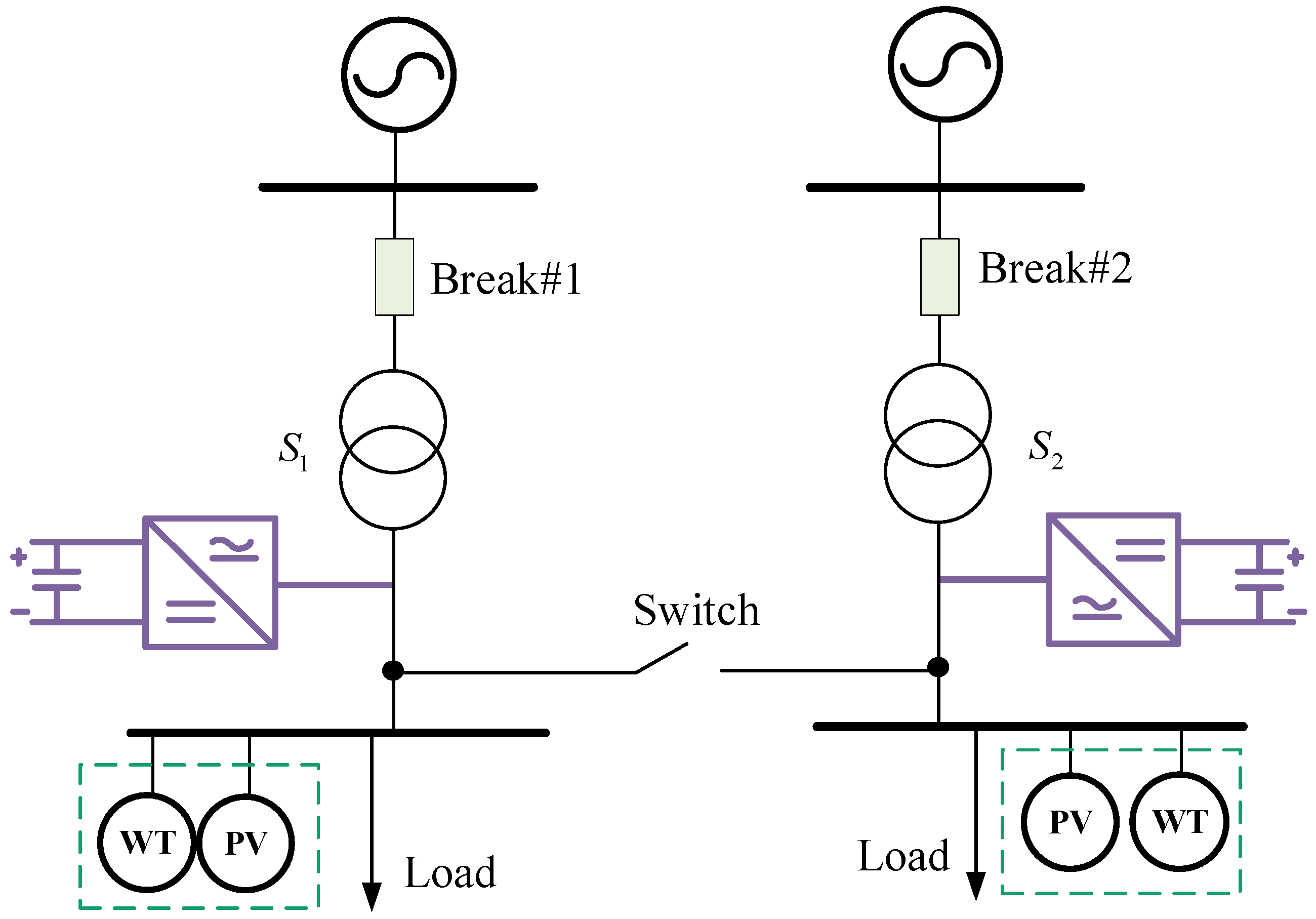
The simplified structure of the interconnected station area of the distribution network is shown in
Figure 1. The distribution system usually adopts a 10 kV medium-voltage distribution network, which supplies power to multiple stations through the distribution network, and each station area is connected to a transformer. The mechanical switch is located at the outlet side of the transformer in the station area, which directly interconnects the geographically adjacent stations to achieve capacity sharing and load balancing between stations.
In the system shown in
Figure 1, under normal operation, the mechanical switches are often open and do not operate in parallel. When a transformer or its superior power supply system fails, the circuit breaker can be disconnected to isolate the branch fault, and the bus coupling switch can be quickly closed to realize the load transfer. In addition, in order to improve the voltage and power quality at the bus, reactive power compensation devices may be configured, such as simple and inexpensive devices such as capacitor compensation or static synchronous compensator (STATCOM) of high-power power electronic devices with stronger control ability and higher cost.
However, there are also some problems to be solved in the above system:
During normal operation, the bus switch is normally open. For wharf power supply, it is actually two independent power supply circuits. When the load capacity of a certain road is close to or even exceeds the capacity of the transformer, considering the safety margin, the power supply system at this time cannot provide full power supply for the station area, but from the total power supply capacity, the capacity of the two transformers is sufficient. Therefore, under the existing power supply structure and operation mode, the transformer capacity cannot be reasonably utilized.
The DC-AC converter on one side can only rely on local information to solve the local power problem, and cannot take into account the extreme conditions such as power overload on the other side of the line.
The high-power power electronic devices installed in the two lines are costly and independent of each other, which cannot solve the problem of unreasonable utilization of transformer capacity in the two lines.
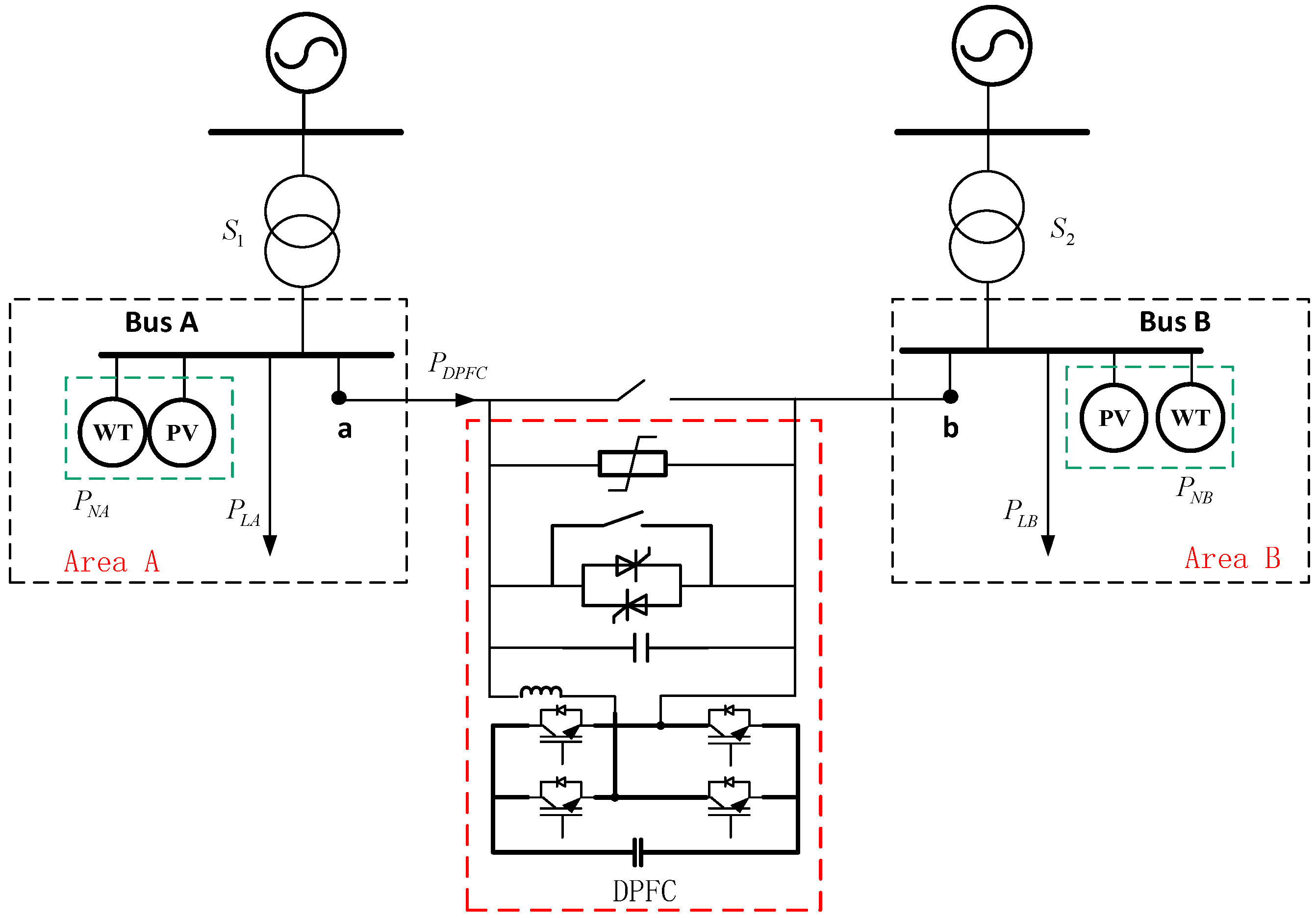
In order to solve the above problems, the distributed power flow controller (DPFC) can be used to implement flexible interconnection on both sides of the AC bus to replace the two sets of independent AC high-power voltage-stabilizing devices in
Figure 1, as shown in
Figure 2.
The new flexible interconnection device shown in
Figure 2 has the following advantages over the independent high-power power electronic device in
Figure 1:
As a flexible interconnection device, the distributed power flow controller in
Figure 2 has only made a simple transformation at the hardware equipment level, that is, replacing two independent DC-AC converters with one set, which greatly reduces the cost and further reduces the volume.
While also having the function of controllable reactive power compensation, it can realize the active power mutual aid of both sides of the line, and solve the problem that the transformer capacity of both sides of the line cannot be reasonably utilized through corresponding control.
This paper intends to use the distributed power flow controller as a flexible interconnection device to formulate a flexible mutual-aid control strategy between interconnected regional power grids, and is committed to solving the problem that the capacity of line transformers cannot be reasonably utilized.
3. Analysis of Interconnection Principle Based on Distributed Power Flow Controller
The distributed power flow controller can output the equivalent voltage with controllable amplitude and phase angle perpendicular to the line current, or the equivalent resistance or equivalent capacitance with controllable impedance, thereby changing the voltage or impedance parameters of the receiving end of the line, and then regulating the active power flow or reactive power flow of the line. The working phasor diagram is shown in
Figure 3a. However, due to the active loss caused by non-ideal components in actual operation, the phase angle difference between the actual output voltage and the line current will be slightly larger than 90°, and the working phasor diagram is shown in
Figure 3b. The active power deviation caused by the additional phase shift remains within 1.2%, and the reactive power error is below 2.0%, which is acceptable for engineering application. The distributed power flow controller can be equivalent to an equivalent voltage source with controllable output amplitude and phase angle. It is equivalent to a variable impedance from the impedance characteristics. It can not only adjust the active and reactive power flow of the interconnected line, but also be used to compensate for the voltage amplitude difference and phase angle difference between the interconnected nodes, as shown in
Figure 3c. In the figure,
is the bus voltage at the beginning of the line.
is the terminal voltage of the line after the equivalent voltage is injected into the DPFC.
and
are the voltage of the interconnection node, respectively.
When the distributed power flow controller is used to realize flexible interconnection, it can regulate the power flow and voltage distribution of the distribution network. As shown in
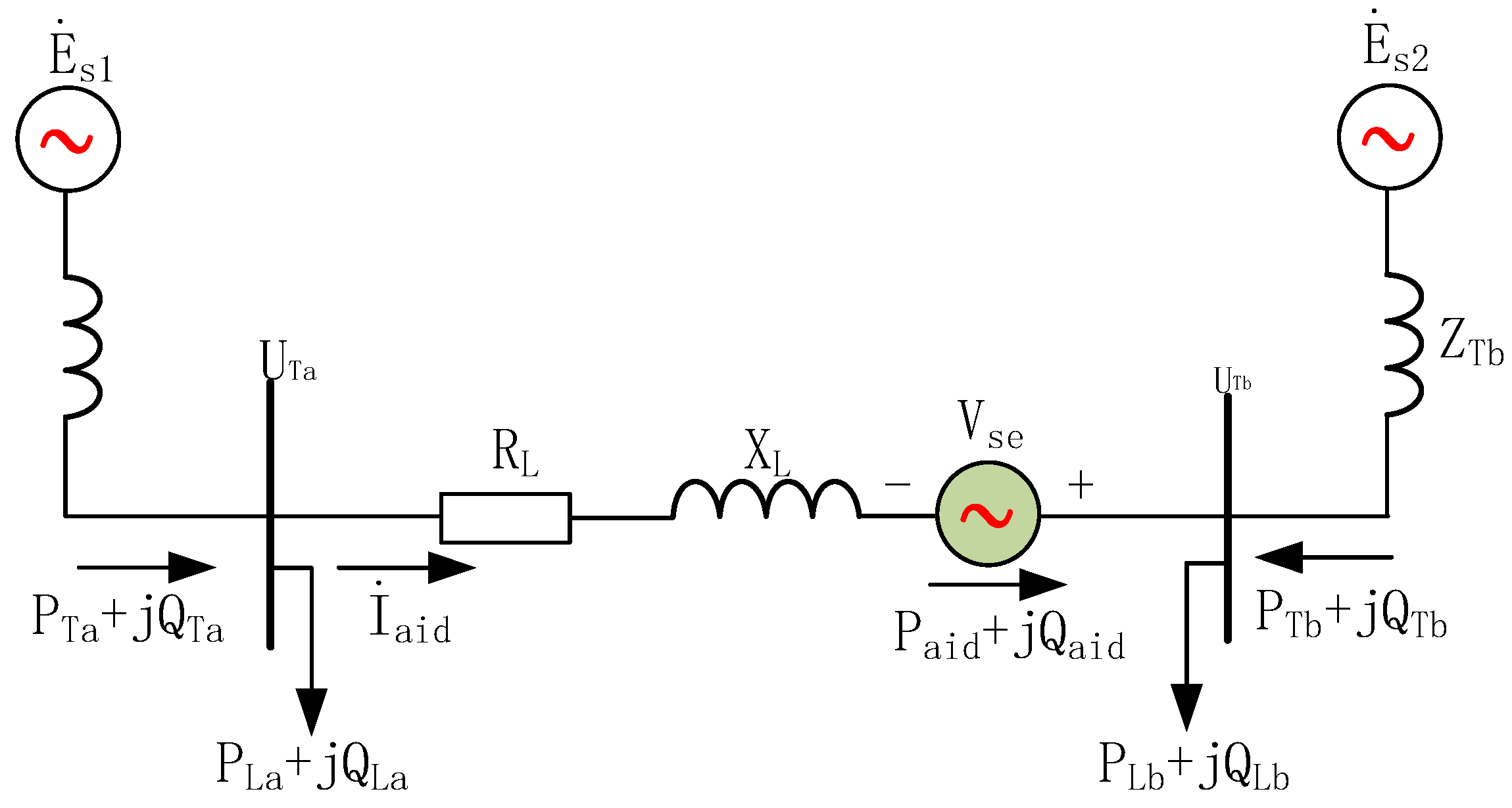
Figure 4, DPFC can be equivalent to a controllable voltage source connected in series on an interconnected line.
Taking the phase of node B voltage as the reference phase, the node voltage before the DPFC is put into operation is
At this time, the current flowing through the interconnected line is
Node A is defined as the head end of the interconnected line. Node B is the end of the interconnected line. Before the DPFC is put into operation, the initial apparent power
at the head of the line and the initial apparent power
at the end of the line are
When the DPFC is connected to the line, the line current
is
When DPFC is connected to the line, the power at the end of the line is
After the DPFC is put into operation, the change in active power and reactive power at the end of the line is
Therefore, the power flow of the regulated interconnected line can be accurately obtained. When the regulation is carried out, the power difference can be calculated according to the target state value of the active and reactive power of the line and the unregulated initial power flow value, and then the amplitude and phase angle of the output voltage of the DPFC can be calculated.
When DPFC regulates the line power flow, the active power flow is usually taken as the control target, and the reactive power flow is the follow-up parameter. At this time, considering the power factor of the line, the phase angle difference between 1 and 2 is very small, and 3 is perpendicular to 4, so it is approximately considered that 5 and 6 are perpendicular, so the line current can be considered as
At this time, the terminal power of the line is
After the DPFC is put into operation, the change in active power and reactive power at the end of the line is
Therefore, the active or reactive power flow of the interconnected line can be accurately regulated. When regulating, the difference between the active or reactive power adjustment target value and the unadjusted initial power flow value can be calculated, and then the voltage amplitude to be output can be calculated.
4. Flexible Mutual Aid Control Strategy
Figure 5 is the equivalent circuit of the DPFC-based interconnected power system. In the diagram, assuming that the bus voltage of the station area is constant in the process of power mutual aid, the phase of the bus voltage of the station area B is taken as the reference phase, and the phase angle of the bus voltage of the station area A is
. In order to analyze the power adjustment range of the DPFC, the phase angle of the output voltage of the DPFC is divided into
After the interconnection of the interconnected area, the mutual power flowing through the interconnected line is
These derivations are based on the small-signal linearization assumptions, namely ΔV/V ≤ 0.05 and Δφ ≤ 5°, and assume the system operates within the range of steady-state small disturbances. Because the reactance of the interconnected line constructed between the stations is much larger than the resistance, the line resistance can be ignored. The assumption that line reactance dominates is valid for typical transformer area interconnections. To verify the negligible impact of resistance, error analysis is conducted using common cable parameters (R = 0.125 Ω/km, X = 0.365 Ω/km). As shown in
Table 1, the calculation error remains below 2.5% for line lengths up to 1000 m, which is within acceptable limits for practical applications.
At this time, the mutual power is
It can be seen from Equations (17) and (18) that the mutual power transmitted by the interconnected lines consists of two parts.
The first part is the natural transmission power determined by the bus voltage of the station and the parameters of the interconnected line.
The second part is the additional forced transfer of mutual power by the DPFC as the interconnection device after the installation of the DPFC device.
After the phase angle difference in the bus voltage in the given station area is
, the adjustment range of
is (−180°, 180°), so the range of additional transfer power of DPFC is
Therefore, the adjustment range of the mutual power of the interconnected line is
The interconnected operation mode proposed in this paper takes the active power flow as the control target and the reactive power flow as the follow-up variable. The following will analyze the target value of active power flow control.
In
Figure 5, the active power balance relationship is
The rated capacity ratio of transformer in transformer area is defined as
In order to reduce the capacity configuration of the transformer in the station area and reduce the capacity increase pressure of the distribution network, the direct purpose of power mutual aid is to realize the reasonable distribution of the transformer capacity in the station area. Assuming that the power factor of the interconnected station area is the same, that is,
, the control target is
According to the above formula, in order to achieve the above objectives, the active mutual power that DPFC should transfer is
If the station area A is connected to the new energy, the equivalent circuit of the station area interconnection based on DPFC is shown in
Figure 5.
is the distributed power generation power of the station area A.
At this time, the active power balance relationship is
Similarly, the active power that should be transferred by DPFC is
In extreme cases, the mutual power transferred by the interconnection device has a maximum value, that is, one distribution transformer is no-load and the other distribution transformer is full-load, and the power factor of the station area is 1, and the full-load load is equal to the transformer capacity, namely
At this time, the transferred mutual power is taken to the maximum.
In the design of the capacity of the interconnection device, it should be ensured that the maximum value of the target mutual power is within the active power regulation range shown in Equation (22) in extreme cases, and then the reference value of the active power regulation of the interconnection device is set according to the above formula, so as to make full use of the transformer capacity of the interconnection station area and realize the reasonable distribution of the transformer capacity of the station area.
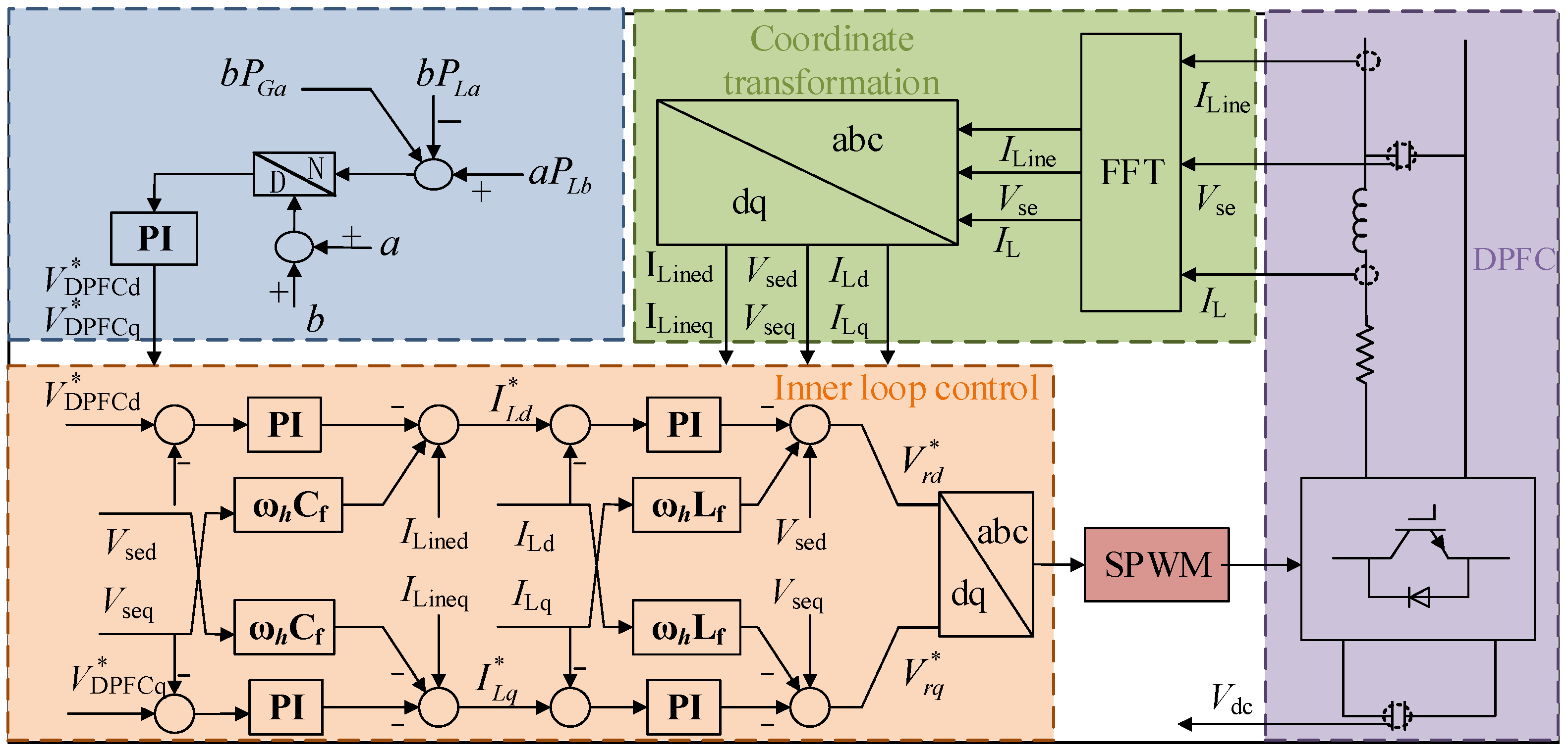
The DPFC control system is shown in
Figure 6. The load power, new energy output and rated capacity ratio of each transformer are collected. The inner PI controller parameters were tuned based on the symmetrical optimum criterion to balance response speed and overshoot. The output voltage d-axis component
and q-axis component
are obtained through the outer-loop control loop of DPFC equipment. The d-axis component and q-axis component of the actual output voltage
of the flexible interconnection device are calculated and compared with the given voltage
and
, and then fed back to the inner-loop control system of the device. Adjust the output voltage of the device to control the active power of the contact line, and realize the power mutual assistance between the power grids in the station area.
5. Simulation Verification
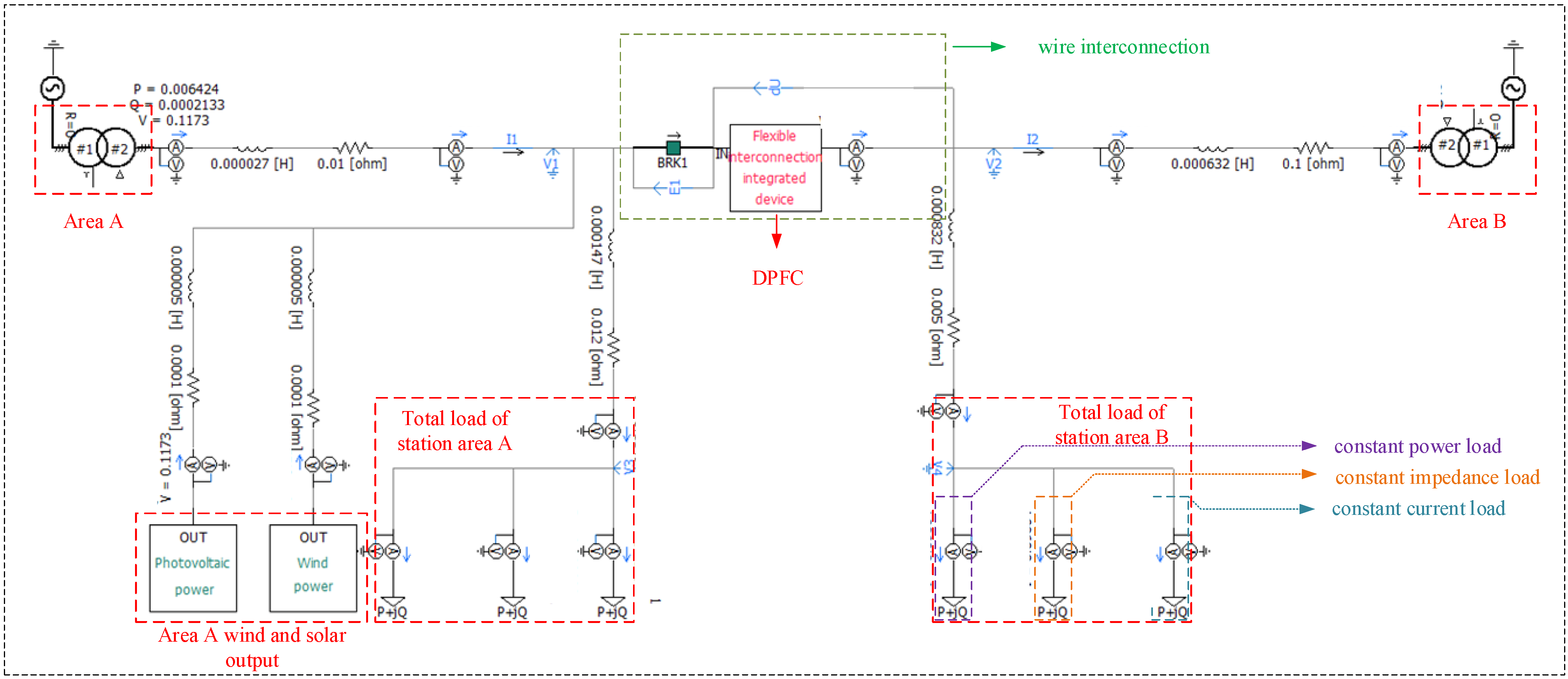
In order to verify the effectiveness of the proposed control strategy, this paper builds a simulation model based on PSCAD/EMTDC, as shown in
Figure 7. The simulation model includes two 10kV/400V distribution transformers; area A has photovoltaic power generation model and wind power generation model, and area B has no new energy model; the load is composed of constant power load, constant impedance load and constant current load.
When the distribution network is carrying out flexible mutual aid, the power required by another area is always supplemented by the new energy consumption surplus station area, and on this basis, the flexible mutual aid control strategy of the device is verified. The simulation scenario is set to the station area A to access the scenery resources. The rated capacity of the transformer in the station area is set to 100 kVA, that is, a:b = 1:1. The power factor of area A and area B is 0.9.
Although the main simulation lasts 1.6 s, an extended 5 s run was conducted to confirm steady-state stability, with no observed oscillations. The simulation test is set as follows: at the moment of 1.0 s, the DPFC executes the station area interconnection and mutual aid control strategy shown in
Figure 6. The simulation model stops running at 1.6 s. From 0.6 s to 1.0 s is the system response time, waiting for the source-load power of the interconnected station area to reach a steady state. Due to the no-load operation of the interconnected device during this period, the steady-state power value is the natural distribution of the power flow after the A and B stations are directly connected. At 1.0 s, the interconnection device performs the control strategy of power mutual assistance stage. The steady-state value after 1.0 s is the result of power mutual assistance in the station area. The steady-state value from 0.6 s to 1.0 s is compared with the steady-state value after 1.0 s, so as to highlight the regulation effect of power mutual assistance stage.
To clarify this configuration, the response time of 0.6–1.0 s is determined based on the dynamic characteristics of the DPFC voltage-control inner loop and the settling time of the outer-loop active power controller. According to the PSCAD/EMTDC simulation of the DPFC switching stage and the measured transient response during step-voltage injection tests, the combined controller exhibits a typical settling time of approximately 0.25–0.35 s. Considering the inherent delay of the distribution transformer and line impedance, an extended window of 0.6–1.0 s was adopted to ensure that the natural power flow state reaches full steady stability before the mutual-aid control stage is activated. This setting ensures reproducible simulation behavior under different load and renewable-generation combinations.
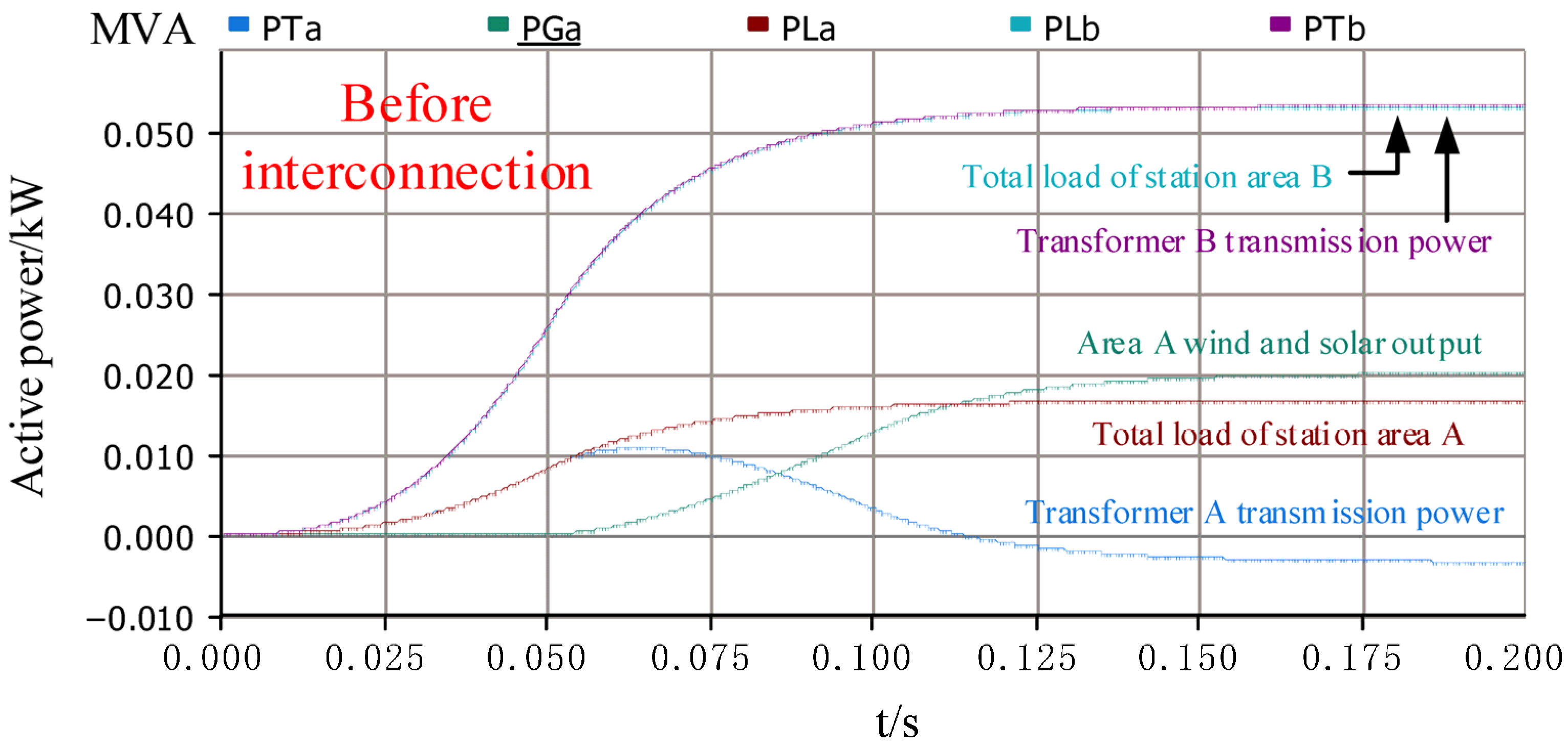
Figure 8 shows the source-load power before the interconnection of the station area. Before the interconnection of the station area, the wind and solar output of the station area A is 20 kW, the total load of the station area A is 16 kW, the transmission power of the transformer A is −4 kW, the total load of the station area B is 54 kW, and the transmission power of the transformer B is 54 kW. It can be seen that before the interconnection of the station area, because the wind and solar output of the station area A is greater than the total load, the power flow of the station area A appears.
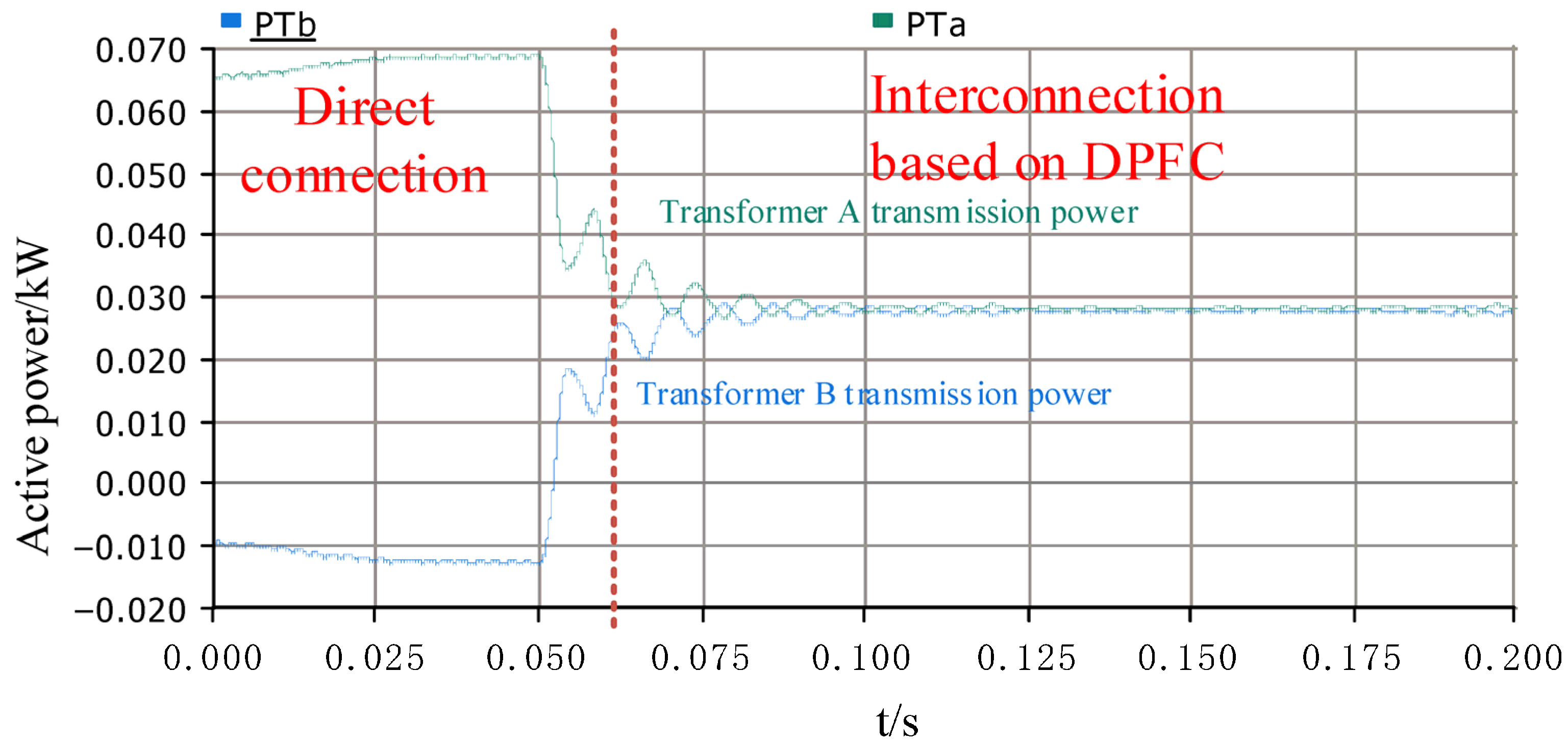
Figure 10 shows the transmission power of the transformer area directly connected to the transformer area through the interconnection device. The two areas are directly interconnected. The transmission power of transformer A is about 69 kW, and the transmission power of transformer B is −11 kW. It can be seen that after the direct interconnection, the power flow reverses in area B, while the transformer in area A has a heavy load, and the use capacity ratio is 76.67%. After the interconnection of the two stations through the interconnection device, the transmission power of transformer A is approximately equal to that of transformer B, both of which are about 27.5 kW. The capacity ratio of distribution transformers in the two stations is 30.56%, which realizes the reasonable distribution of transformer capacity in the station area and solves the problem of power flow reversal in the station area.
The use of transformer capacity in the station area is shown in
Figure 10.
Utilization (%) = . For example, in the mutual-aid mode, transformer A’s utilization is 27.5/90 = 30.6%. Through the above simulation results, it can be concluded that the flexible mutual-aid control strategy between the interconnected regional power grids based on the distributed power flow controller is effective. DPFC can regulate the mutual-aid power so that the real-time capacity of the interconnected transformer area can be distributed according to the rated capacity ratio, and solve the problems of light load operation capacity waste, heavy load operation, overload operation and power flow reversal of the transformer area.
Although conducting a full comparative simulation among multiple flexible interconnection devices such as the Soft Open Point (SOP) and the Flexible Looped Network Controller (FLNC) would provide additional insights, such comparisons were not included in this study because the modeling scope and PSCAD/EMTDC framework used herein focus specifically on validating the feasibility and performance of the proposed DPFC-based mutual-aid strategy. SOP and FLNC involve fundamentally different topologies—centralized back-to-back converters for SOP and coordinated multi-terminal power electronic nodes for FLNC—which require substantial additional modeling, parameter identification, and control interface development that fall outside the intended scope of this work.
Nevertheless, based on the established operational characteristics reported in the existing literature, the DPFC offers several recognized intrinsic advantages under the same application scenario. These include the following:
A faster control response due to its distributed series–injection structure without a large DC-link energy-storage constraint;
Reduced installation capacity because the DPFC modules operate in a distributed manner along the line;
Higher active power regulation accuracy enabled by direct voltage–phase injection at the interconnection point.
These characteristics collectively explain the performance improvements observed in the presented simulation results, even though a full device-to-device comparative experiment is not included. Future work will incorporate detailed benchmarking among DPFC, SOP, and FLNC under unified test conditions to more comprehensively quantify the performance differences.
6. Conclusions
This paper presents a flexible mutual-aid control strategy for interconnected transformer areas based on the distributed power flow controller (DPFC) to solve the problems of uneven transformer loading and reverse power flow in traditional distribution networks. The proposed method establishes a capacity-ratio-oriented control model, enabling the DPFC to regulate active power according to the rated capacities of transformers and realize dynamic, bidirectional power transfer between interconnected areas. Simulation results in PSCAD/EMTDC demonstrate that the proposed strategy effectively balances transformer loading, reducing the imbalance from 76.67% to 30.56% and eliminating reverse power flow at the receiving station. The steady-state transferred power reaches about 27.5 kW, consistent with analytical predictions. Compared with Soft Open Point (SOP) configurations, the DPFC offers faster response, lower converter capacity, and improved control precision, verifying its practicality for low-voltage transformer coordination. Future work will extend this approach to multi-terminal interconnections and conduct experimental validation in real distribution networks.
