Abstract
The growing demand for internet-of-vehicles (IoV) communication requires compact antennas capable of supporting multiple frequency bands while maintaining stable radiation characteristics. This paper presents the design and validation of a multilayer microstrip patch antenna that achieves dual-band operation through the integration of shorting vias, a coupled ring, and an embedded parasitic patch. Parametric studies confirm that the adopted techniques yield impedance bandwidths of 28% at 1.8 GHz and 6.4% at 2.4 GHz, with a low-profile structure of . Measured results demonstrate omnidirectional radiation patterns across the intended bands with a maximum gain of 4.46 dBi at 2.57 GHz. Beyond simulated and laboratory verification, field tests were conducted using LTE communication to evaluate the antenna’s quality of service (QoS) under realistic vehicular conditions. To reduce system cost and simplify testing, a low-cost in-house signal meter based on a Raspberry Pi microcontroller was developed and employed to compare the proposed antenna with a commercial monopole. The results confirm that the multilayer patch antenna provides improved bandwidth, gain, and radiation stability, making it a compact and cost-effective candidate for multiband IoV and V2X communication systems.
1. Introduction
The Internet of Vehicles (IoV), an evolution of vehicular ad hoc networks (VANETs), has emerged as a key enabler of intelligent transportation systems. By supporting vehicle-to-everything (V2X) communications, IoV extends the Internet-of-Things (IoT) paradigm to vehicles, enabling real-time data exchange among vehicles, roadside infrastructure, and cloud services. Such connectivity underpins safety, traffic efficiency, and energy management applications. While advanced standards such as dedicated short-range communication (DSRC) and cellular V2X (C-V2X) are being developed, existing networks including long-term evolution (LTE) and wireless local area networks (WLANs) remain critical for near-term IoV deployment because of their ubiquity and reliability [1,2,3]. The performance of these systems, however, depends strongly on the antenna subsystems integrated into vehicles [4,5].
Vehicular antennas must be compact, rugged, and multiband while maintaining omnidirectional radiation to ensure link stability regardless of orientation. Conventional whip antennas, though still common, are tall (≈), mechanically fragile, and aesthetically intrusive. To overcome these drawbacks, Delaveaud et al. [6] introduced the monopolar wire-patch antenna, and Economou and Langley [7] demonstrated a triangular dual-band patch with monopole-like radiation. These early monopolar designs, however, offered narrow bandwidths (1.5–3%), insufficient for modern vehicular LTE B1/B3 standards.
Subsequent works sought to enhance bandwidth using structural innovations. Al-Zoubi et al. [8] employed coupled rings to generate additional resonances, while Liu et al. [9] showed that multiple shorting vias broaden the impedance response. Chen and Dou [10] extended this concept using non-uniform via arrays and ring slots, achieving bandwidths near 32%. Further improvements include ultra-low-profile monopoles [11], coupled-fed filtering patches [12], substrate-integrated-waveguide (SIW) monopoles [13], and omnidirectional filtering patches with multi-state operation [14]. Characteristic-mode-based approaches have also been applied to optimize UWB and multiband monopolar antennas [15,16].
Recently, IoV-specific antenna designs have gained momentum. Li et al. [17] proposed an ultra-thin multiband logo antenna, Lakshmi et al. [18] introduced a flexible conformal antenna for sub-6 GHz vehicular use, and Yahya et al. [19] reported a compact dual-band V2V antenna. Kannappan et al. [20] developed transparent tri-band antennas, while Keshavarz et al. [21] demonstrated dual-band vehicular MIMO arrays. Yadav et al. [22] also introduced a multiband high-frequency antenna targeting 6G and automotive radar Despite these advances, many reported IoV antennas either lack sufficient bandwidth to simultaneously cover LTE B1/B3 and WLAN, depend on costly substrates, or omit real-world vehicular validation.
To address these challenges, this work proposes a multilayer microstrip patch antenna that combines structural simplicity, cost-effectiveness, and robust wideband performance across key IoV frequency bands. The main contributions are summarized below:
- A compact multilayer patch antenna is designed for dual-band operation at LTE B1/B3 and WLAN frequencies.
- The antenna achieves 28% and 6.4% measured impedance bandwidths with a low profile of , far shorter than conventional monopoles.
- Integration of shorting vias, a coupled ring, and an embedded parasitic patch enables broadband matching and omnidirectional radiation.
- Two-stage validation—anechoic-chamber measurements and LTE field trials—confirms stable radiation, 4.46 dBi peak gain, and improved signal strength, SNR, and throughput compared with a commercial monopole.
- The antenna offers low-cost FR-4 implementation, robust multiband IoV/V2X performance, and scalability for vehicular communication systems.
Our design originates from a circular monopolar patch operating in the mode, known for omnidirectional radiation [6,7]. We (i) introduce a distributed shorting-via array to excite a composite response [9,10]; (ii) add a coupled ring to tune the effective electrical size and control mode spacing [8]; and (iii) embed a vertically spaced parasitic patch to reshape impedance and create an additional controlled resonance. Co-optimizing the ring dimensions , via placement , and parasitic parameters yields dual impedance bandwidths of 28% (1.71–2.28 GHz) and 6.4% (2.41–2.57 GHz) with monopole-like radiation at a profile on FR-4. The design is experimentally verified through chamber and vehicular field measurements, demonstrating simultaneous wide LTE B1/B3 and WLAN coverage, sub- height, and practical IoV applicability.
2. Antenna Design and Optimization
2.1. Antenna Geometry
The geometry of the proposed antenna is shown in Figure 1a–c, with key dimensions listed in Table 1. A circular radiating patch is implemented on a two-layer FR-4 stack (, ) of radius . The upper metallization hosts the main patch and a concentric coupled ring (inner radius a, outer radius b) (Figure 1a), while an embedded parasitic patch of radius is placed between the substrates above the ground plane (Figure 1b). Although the parasitic patch geometrically overlaps the feed and via ring regions, small clearance gaps are provided around these elements to prevent direct electrical contact while preserving electromagnetic coupling. Fifteen shorting vias of radius r, equally spaced on a circle of radius d, connect the radiator to ground. A 50 coaxial probe feeds the antenna at the center. For visibility, Figure 1c exaggerates metal thicknesses.
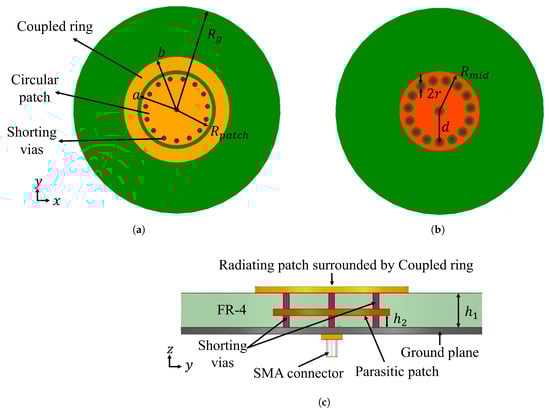
Figure 1.
Geometry of the proposed antenna: (a) top view of the upper layer showing the circular radiating patch () and coupled ring (inner a, outer b) with shorting vias (radius r) on the FR-4 substrate of radius ; (b) top view of the embedded parasitic patch layer () between substrates, indicating the via circle of radius d and via diameter ; (c) side view (thickness exaggerated) showing the stacked FR-4 layers (), parasitic patch, shorting vias, and coaxial feed. Clearance gaps around the feed and vias prevent direct contact with the parasitic patch.

Table 1.
Key design parameters of the antenna.
The monopole-like azimuth pattern arises from in-phase vertical currents on the central probe and shorting vias [6,7]; Figure 2 shows the strongest, in-phase currents at these locations [10]. The distributed via ring also enables miniaturization, yielding a profile at 1.7 GHz.
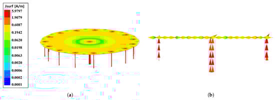
Figure 2.
Simulated surface current at ∼1.8 GHz: (a) magnitude; (b) phase.
FR-4 (≈, ≈) was adopted as a practical substrate balancing bandwidth, efficiency, cost, and mechanical robustness. A lower- material (e.g., Rogers RT/Duroid 5880) would improve radiation efficiency and bandwidth but increase patch diameter by ∼30–35%; a higher- substrate would reduce footprint but narrow impedance bandwidth and lower efficiency. Alternative miniaturization (e.g., slots, meanders, reactive surfaces, local high- loading) is possible if further size reduction is required.
2.2. Resonance Behavior and Bandwidth Enhancement
Design sequence: (1) Size the circular patch for the mode near the low band using the cavity model [23]. (2) Place a via ring at radius d to lower input resistance and broaden the low-band match through coupling [6,9,10]. (3) Add a coupled ring and tune to control resonance placement and spacing [8]. (4) Embed a parasitic patch at height and adjust to introduce a controlled resonance and flatten the impedance. (5) Co-optimize for ≈ matching across both bands while preserving the monopole-like radiation of Section 2.
The circular patch is approximated by a cylindrical cavity with resonances [23]:
where includes fringing and is the n-th root of . The dominant mode provides the monopole-like radiation; shorting vias also excite , broadening the impedance response [6,9].
Parasitic-patch effect: Figure 3 compares input impedances with and without the parasitic patch, showing markedly improved matching across LTE and WLAN when coupled. Without the parasitic patch, the input impedance is high near 2.4 GHz; introducing the patch lowers the impedance around 2.6 GHz and raises it at ∼2.3 GHz, smoothing broadband coverage.
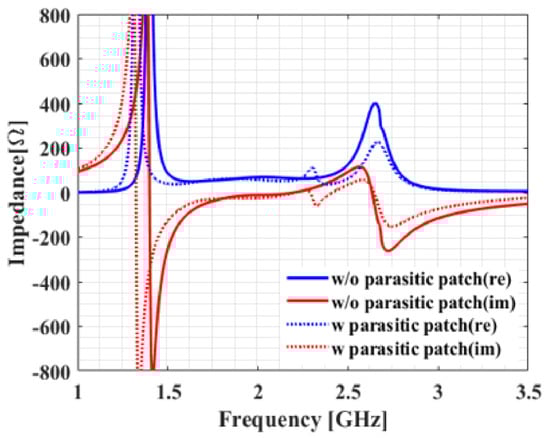
Figure 3.
Input impedance with and without the embedded parasitic patch.
The parametric responses in Figure 4 isolate the effects of the parasitic patch’s height and radius while holding all other parameters at their optimized values (Table 1). In Figure 4a, increasing reduces the separation between the parasitic and top patches, strengthening interlayer coupling. This brings the two resonant minima closer together and broadens the overall response, but the effective dB impedance bandwidth narrows because the return loss becomes shallower. Smaller values (weaker coupling) yield clearer mode separation and deeper minima, resulting in improved dual-band impedance matching.
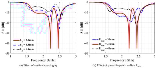
Figure 4.
Simulated reflection-coefficient responses showing the influence of the embedded parasitic patch. (a) Increasing strengthens interlayer coupling, bringing the resonant minima closer and broadening the response but with shallower return-loss depth. (b) Increasing enlarges electrical size and shifts both resonances downward (decreasing shifts them upward). All other parameters are fixed at their optimized values in Table 1.
Design trade-off: Coupling strength via and resonance alignment via set the bandwidth–matching trade-off: stronger coupling (larger ) enhances interaction but reduces return-loss depth; weaker coupling (smaller ) deepens minima but narrows overall bandwidth. The optimized geometry in Table 1 maintains both LTE and WLAN bands below dB with smooth impedance and stable radiation.
The effect of the coupled ring is addressed next (Section 2.3), where control the placement and bandwidth (Figure 5).
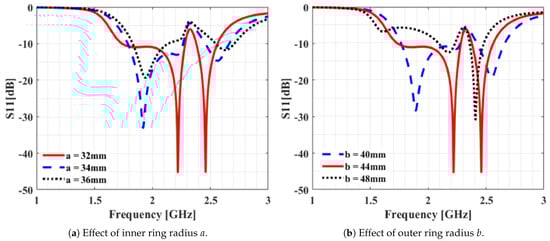
Figure 5.
Simulated reflection-coefficient responses showing the influence of the coupled ring on the resonance and impedance bandwidth. (a) Increasing the inner radius a (narrowing the ring) shifts both resonances upward; low-band matching improves initially but degrades beyond an intermediate value ( mm), narrowing the bandwidth. (b) Increasing the outer radius b (widening the ring) shifts both resonances downward and strengthens coupling, broadening the low-band response but yielding shallower minima. Overall, a and b govern a trade-off between bandwidth and return-loss depth. All other parameters are fixed at their optimized values in Table 1.
2.3. Coupled Ring Optimization
The coupled ring modifies the boundary fields of the circular patch, effectively tuning the resonance predicted by the cavity model in Equation (1). Varying the ring radii alters the effective cavity radius : increasing the outer radius b (widening the ring) lowers both resonant frequencies, while increasing the inner radius a (narrowing the ring) shifts them upward. This provides a convenient geometric handle for positioning and separating the operating bands without disturbing the monopole-like radiation established by the feed and via currents.
Beyond frequency tuning, the ring functions as a weakly coupled resonator that interacts with the mode, flattening the input-reactance slope and broadening the dB impedance bandwidth. This behavior follows classical coupled-resonator theory [24,25] and has been experimentally verified for ring-coupled circular patches exhibiting broadband, monopole-like radiation [8]. In the present design, the coupled ring therefore serves two primary roles: (i) bandwidth enhancement and (ii) dual-band co-tuning in conjunction with the embedded parasitic patch.
Figure 5a,b illustrate the parametric influence of the inner and outer ring radii. Increasing a shifts both resonances upward and initially improves the low-band return loss, but beyond an intermediate value ( mm) the matching degrades and the bandwidth narrows. Conversely, increasing b lowers both resonances and strengthens coupling between the ring and main radiator: larger b values broaden the low-band response but yield shallower minima, while smaller b values produce deeper matching but narrower bandwidth.
Overall, the parameters a and b control a clear trade-off between bandwidth and matching depth. Stronger coupling (larger b, smaller a) enhances bandwidth at the cost of reduced return-loss depth, whereas weaker coupling (smaller b, larger a) deepens the minima but narrows the bands. The optimized combination reported in Table 1 achieves balanced coupling, maintaining reflection coefficients below dB across the LTE and WLAN bands with smooth transitions between resonances.
3. Experimental Validation
With the optimized geometry established, a prototype was fabricated and experimentally characterized to validate the simulated design outcomes. A photograph of the prototype (top view) is shown in Figure 6a, while the setup for reflection coefficient measurement is shown in Figure 6b. The total height is less than 10 mm, which is significantly lower than that of a conventional quarter-wavelength monopole. The measurement setup for radiation pattern evaluation is shown in Figure 7, where the antenna under test was placed in an anechoic chamber with a standard horn antenna as the receiving probe.
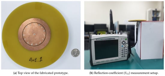
Figure 6.
Fabricated prototype and measurement setup: (a) top view of the prototype; (b) measurement using a vector network analyzer.
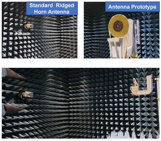
Figure 7.
Far-field radiation measurement in the anechoic chamber.
The simulated and measured reflection coefficients (), obtained using ANSYS HFSS R2021 and a vector network analyzer, are compared in Figure 8a. Good agreement is observed between simulation and measurement. The measured impedance bandwidths, defined by dB, are 28% (1710–2280 MHz) and 6.4% (2410–2570 MHz), fully covering LTE Bands B3/B1 and the 2.4 GHz WLAN band.
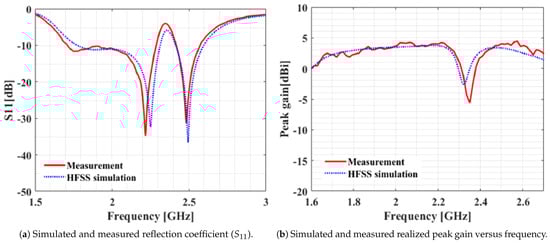
Figure 8.
Simulated and measured results of the proposed antenna: (a) reflection coefficient; (b) realized peak gain across 1.6–2.7 GHz.
The measured and simulated realized gains from 1.6–2.7 GHz are presented in Figure 8b. Both exhibit strong correlation, with a maximum measured gain of 4.46 dBi at 2.57 GHz. The localized gain reduction near 2.35 GHz coincides with the notch region between the two resonant modes in Figure 8a. This frequency lies outside LTE Band 1 (2110–2170 MHz) and corresponds to the transition between the -dominated low-band mode (covering LTE B3/B1) and the -coupled high-band mode (covering 2.4 GHz WLAN). In this inter-band region, out-of-phase surface currents on the main and parasitic patches produce partial radiation cancellation, leading to the observed dip in gain. Within LTE B1/B3, however, the realized gain remains above 2 dBi and varies only slightly across the sub-bands, maintaining omnidirectional azimuth radiation as shown in Figure 9. This stable sub-band behavior ensures robust IoV and LTE performance at the upper edge of the low band.
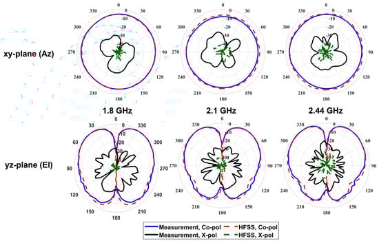
Figure 9.
Simulated and measured azimuth (Az) and elevation (El) radiation patterns at 1.8, 2.1, and 2.44 GHz. Co- and cross-polar traces are overlaid and normalized to the peak co-polar level.
Although radiation efficiency was not directly measured, full-wave simulations using FR-4 () predict efficiencies of approximately 70–85% across the operating bands. Slightly lower efficiency at the upper band (2.4–2.6 GHz) results from increased dielectric and conductor losses, yet the achieved gain and bandwidth confirm that the antenna maintains acceptable performance for low-cost IoV and IoT applications.
Radiation patterns at 1.8, 2.1, and 2.44 GHz—the center frequencies of the target bands—are shown in Figure 9. Measured and simulated co- and cross-polarized traces are overlaid and normalized to the peak co-polar level; the black solid line denotes the measured cross-polarization. The antenna exhibits omnidirectional azimuth patterns () with vertical polarization, consistent with a monopole-like radiator. The azimuthal cross-polar discrimination (XPD) remains above 15 dB across all frequencies, confirming good polarization purity. Similar behavior is observed in elevation, except near nulls where the co-polar reference level is minimal. Overall, the antenna demonstrates stable radiation patterns and sufficient polarization isolation for vehicular and IoT multipath environments.
A comparison with representative omnidirectional and multiband patch antennas is summarized in Table 2. The proposed design achieves the widest low-band fractional bandwidth while maintaining a lower profile on cost-effective FR-4. Compared with the early monopolar patch in [7], the proposed antenna provides substantially broader impedance bandwidth at the low band while retaining an even lower electrical profile. More recent IoV-oriented solutions—such as flexible conformal, logo-integrated, and compact vehicular patches [17,18,19]—offer application-specific advantages but do not simultaneously achieve wide LTE B1/B3 coverage, omnidirectional radiation, sub- height, and low-cost FR-4 fabrication as demonstrated here.
Table 2.
Comparison with representative omnidirectional/multiband patch antennas relevant to IoV applications.
Although the present work focuses on a single radiator, its measured characteristics indicate suitability for multi-element integration in IoV terminals. The antenna maintains vertical polarization, omnidirectional azimuth radiation, and stable gain across LTE B1/B3 and WLAN bands—features that typically yield low envelope correlation and strong diversity performance in vehicular MIMO arrays [26,27,28]. Comparable compact elements achieve ECC values below 0.1 with inter-element spacing of approximately 0.4–0.6. Comprehensive array characterization, including mutual coupling and ECC measurement, is reserved for future work.
4. Field Validation of LTE Performance for IoV
Following the simulated and chamber measurements that confirmed the antenna’s wide impedance bandwidth, omnidirectional radiation, and stable gain, a field validation was conducted to assess its behavior under realistic vehicular conditions, as emphasized in recent IoV studies [20,21]. An in-house LTE signal meter, implemented on a Raspberry Pi microcontroller, was used for the drive test. The system integrates a Quectel EC25 LTE module via USB and measures key performance indicators (KPIs)—received signal strength indicator (RSSI), reference signal received power (RSRP), reference signal received quality (RSRQ), signal-to-noise ratio (SNR), and data throughput—according to 3GPP definitions [29].
A photograph and block diagram of the signal meter are shown in Figure 10. During the field test, the proposed antenna and a commercial monopole were mounted on the roof of an autonomous vehicle (Figure 11) and connected to the signal meter via coaxial cables for simultaneous performance evaluation. The commercial monopole, operating over 704–960 MHz and 1710–2690 MHz with a 110 mm height, served as a practical reference representative of widely used vehicular and IoT antennas. Its overlapping LTE B1/B3 and 2.4 GHz WLAN coverage provided a relevant baseline for assessing real-world communication quality under identical conditions.
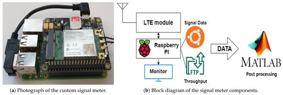
Figure 10.
Prototype of the developed LTE signal meter used for field validation.
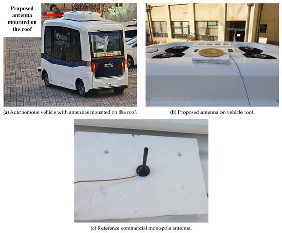
Figure 11.
Field-test configuration for LTE-IoV validation.
The field-test results, summarized in Figure 12, compare the proposed antenna and the commercial monopole under identical drive-test conditions. Power-related KPIs (RSSI, RSRP, RSRQ, and SNR) were averaged across the route, while data throughput was continuously recorded. The proposed antenna achieved approximately 7 dB and 6 dB higher RSSI and SNR, respectively, with more stable throughput despite being nearly one-tenth the height of the monopole. These results confirm that the low-profile design provides robust link quality and high QoS for vehicular IoV communications.
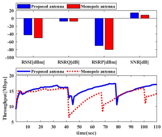
Figure 12.
Measured field-test results showing RSSI, RSRP, RSRQ, and SNR for the proposed and reference antennas.
Table 3 compares the two antennas. Although the commercial monopole exhibits slightly higher peak gain, it occupies over ten times the physical height. The proposed antenna, fabricated on FR-4, achieves competitive gain while maintaining compact dimensions and complete LTE/WLAN coverage, underscoring its practicality for IoV integration.
Table 3.
Comparison of antennas evaluated in the field test.
While this study primarily focused on electromagnetic performance, environmental factors such as temperature variation, humidity, and mechanical vibration may affect impedance stability and efficiency in long-term IoV operation. Future work will include environmental qualification tests and integration of protective features such as a low- radome, hydrophobic coating, and corrosion-resistant materials to ensure durability and performance consistency.
5. Conclusions
This paper presented a multilayer microstrip antenna that combines a circular patch with shorting vias, a coupled ring, and an embedded parasitic patch for Internet-of-Vehicles (IoV) terminals to realize dual-band operation at 1.8 GHz (LTE B3) and 2.4 GHz (WLAN). The prototype, implemented on low-cost FR-4, achieves measured impedance bandwidths of 28% and 6.4% with a compact profile of .
Performance was validated in two stages. Anechoic-chamber measurements confirmed wideband matching, omnidirectional patterns, and a peak realized gain of 4.46 dBi. Field trials using an in-house Raspberry Pi-based LTE meter further demonstrated improved RSSI, SNR, and throughput versus a commercial vehicular monopole, despite the proposed antenna’s much lower profile.
These results indicate a practical, scalable radiator that combines compact size, robust omnidirectional radiation, and economical fabrication for multiband IoV/V2X connectivity.
Author Contributions
Conceptualization, J.-Y.C.; software, S.B. and E.T.A.; validation, S.B. and E.T.A.; formal analysis, S.B. and E.T.A.; investigation, S.B. and E.T.A.; resources, J.-Y.C.; writing—original draft preparation, S.B. and E.T.A.; writing—review and editing, E.T.A.; visualization, S.B. and E.T.A.; supervision, J.-Y.C.; project administration, J.-Y.C.; funding acquisition, J.-Y.C. All authors have read and agreed to the published version of the manuscript.
Funding
This research was supported by Seoul National University of Science and Technology.
Data Availability Statement
The original contributions presented in this study are included in the article. Further inquiries can be directed to the corresponding author.
Acknowledgments
The authors used ChatGPT (OpenAI and GPT-5) to assist with language refinement. All content was carefully reviewed, edited, and verified by the authors, who take full responsibility for the final manuscript.
Conflicts of Interest
The authors declare no conflicts of interest.
References
- Hartenstein, H.; Laberteaux, K.P. A Tutorial Survey on Vehicular Ad Hoc Networks. IEEE Commun. Mag. 2008, 46, 164–171. [Google Scholar] [CrossRef]
- Molina-Masegosa, R.; Gozalvez, J. LTE-V for Sidelink 5G V2X Vehicular Communications. IEEE Veh. Technol. Mag. 2017, 12, 30–39. [Google Scholar] [CrossRef]
- Contreras-Castillo, J.; Zeadally, S.; Guerrero-Ibáñez, J.A. Internet of Vehicles: Architecture, Protocols, and Security. IEEE Internet Things J. 2018, 5, 3701–3709. [Google Scholar] [CrossRef]
- Chung, M.-A.; Tseng, K.-C.; Meiy, I.-P. Antennas in the Internet of Vehicles: Application for X-Band and Ku-Band in Low-Earth-Orbiting Satellites. Vehicles 2023, 5, 55–74. [Google Scholar] [CrossRef]
- Khan, S.; Mazhar, T.; Shahzad, T.; Bibi, A.; Ahmad, W.; Khan, M.A.; Saeed, M.M.; Hamam, H. Antenna systems for IoT applications: A review. Discov. Sustain. 2024, 5, 412. [Google Scholar] [CrossRef]
- Delaveaud, C.; Leveque, P.; Jecko, B. New kind of microstrip antenna: The monopolar wire-patch antenna. Electron. Lett. 1994, 30, 1–2. [Google Scholar] [CrossRef]
- Economou, L.; Langley, R.J. Patch antenna equivalent to simple monopole. Electron. Lett. 1997, 33, 727–729. [Google Scholar] [CrossRef]
- Al-Zoubi, A.S.; Yang, F.; Kishk, A.A. A broadband center-fed circular patch–ring antenna with a monopole-like radiation pattern. IEEE Trans. Antennas Propag. 2009, 57, 789–792. [Google Scholar] [CrossRef]
- Liu, J.; Shen, Z.; Gong, Y.; Lin, F. Design and analysis of a low-profile and broadband microstrip monopolar patch antenna. IEEE Trans. Antennas Propag. 2013, 61, 11–18. [Google Scholar] [CrossRef]
- Chen, X.; Dou, H. Wideband patch antenna with shorting vias. Int. J. Antennas Propag. 2022, 2022, 2578409. [Google Scholar] [CrossRef]
- Ha, Y.; Jung, J.-i.; Lee, S.; Pyo, S. Extremely low-profile monopolar microstrip antenna with wide bandwidth. Sensors 2021, 21, 5295. [Google Scholar] [CrossRef] [PubMed]
- La, D.-S.; Zhao, J.-H.; Chen, S.-M.; Zhang, C.-X.; Qu, M.-J.; Guo, J.-W. Dual-band omnidirectional coupled-fed monopolar filtering antenna. Eng. Sci. Tech. Int. J. 2022, 35, 101188. [Google Scholar] [CrossRef]
- Yu, S.; Cheng, F.; Gu, C.; Zhang, B.; Huang, K. Substrate integrated waveguide omnidirectional filtering antenna with a controllable radiation null for 5.8 GHz WiFi application. Int. J. RF Microw. Comput.-Aided Eng. 2022, 32, e23007. [Google Scholar] [CrossRef]
- Huang, J.; Zhu, J.; Li, H.; Ma, D.; Tang, H.; Ge, J.; Zhang, X.-F.; Zhou, L.-H.; Chen, J.-X. Filtering wideband omnidirectional patch antenna with four operation states. AEU Int. J. Electron. Commun. 2024, 177, 155223. [Google Scholar] [CrossRef]
- Xiang, Z.; Wang, Z.; Li, C.; You, R. Design of UWB monopole antenna with ring structure based on characteristic mode theory. Prog. Electromagn. Res. C 2025, 158, 225–234. [Google Scholar]
- Fazal, D.; Khan, Q.U.; Hong, I.-P. Multiband Antenna Design with Enhanced Radiations Using Characteristic Mode Analysis. Sci. Rep. 2023, 13, 17829. [Google Scholar] [CrossRef]
- Li, J.; Huang, J.; He, H.; Wang, Y. An Ultra-Thin Multi-Band Logo Antenna for Internet of Vehicles Applications. Electronics 2024, 13, 2792. [Google Scholar] [CrossRef]
- Lakshmi, M.N.V.K.; Prasad, A.M. Design of high flexible multi-band conformal printed patch antenna for sub-6 GHz 5G-based vehicular communication. Int. J. Electron. 2024, 112, 1494–1515. [Google Scholar] [CrossRef]
- Yahya, M.S.; Soeung, S.; Musa, U.; Samaila, Y.A.; Yunusa, Z.; Hamzah, S.A.B. A compact dual-band antenna for enhanced vehicle-to-vehicle communication. Transp. Res. Procedia 2025, 84, 370–377. [Google Scholar] [CrossRef]
- Kannappan, L.; Palaniswamy, S.K.; Kanagasabai, M.; Rajakani, R.; Sundarsingh, E.F.; Alsath, M.G.N. Quad-port multiservice integrated optically transparent automotive antenna for vehicular classification applications. Sci. Rep. 2023, 13, 17614. [Google Scholar] [CrossRef]
- Keshavarz, R.; Winson, D.; Lipman, J.; Abolhasan, M.; Shariati, N. Dual-band, slant-polarized MIMO antenna set for vehicular communication. In Proceedings of the 2023 17th European Conference on Antennas and Propagation (EuCAP), Florence, Italy, 26–31 March 2023; pp. 1–5. [Google Scholar] [CrossRef]
- Yadav, S.V.; Yadav, M.V.; Yadav, D.; Yadav, R.S.; Kumar, R. Multi-band high-frequency antenna for satellite, automotive radar, and 6G communication. Sci. Rep. 2025, 15, 30400. [Google Scholar] [CrossRef] [PubMed]
- Balanis, C.A. Antenna Theory: Analysis and Design, 4th ed.; Wiley: Hoboken, NJ, USA, 2016. [Google Scholar]
- Pozar, D.M. Microwave Engineering, 4th ed.; Wiley: Hoboken, NJ, USA, 2011. [Google Scholar]
- Hong, J.-S.; Lancaster, M.J. Microstrip Filters for RF/Microwave Applications; Wiley: New York, NY, USA, 2001. [Google Scholar]
- Blanch, S.; Romeu, J.; Corbella, I. Exact representation of antenna system diversity performance from input parameter description. Electron. Lett. 2003, 39, 705–707. [Google Scholar] [CrossRef]
- Sharawi, M.S. Printed MIMO Antenna Engineering; Artech House: Norwood, MA, USA, 2014. [Google Scholar]
- Sultan, A.; Jabeen, S.; Fazal, D.; Khan, Q.U. Dual-band dual-polarized MIMO design for vehicular applications. AEU—Int. J. Electron. Commun. 2023, 170, 154772. [Google Scholar] [CrossRef]
- ETSI TS 136 214 V17.0.0; LTE; Evolved Universal Terrestrial Radio Access (E-UTRA); Physical Layer; Measurements. ETSI 3rd Generation Partnership Project (3GPP): Valbonne-Sophia Antipolis, France, 2022.
Disclaimer/Publisher’s Note: The statements, opinions and data contained in all publications are solely those of the individual author(s) and contributor(s) and not of MDPI and/or the editor(s). MDPI and/or the editor(s) disclaim responsibility for any injury to people or property resulting from any ideas, methods, instructions or products referred to in the content. |
© 2025 by the authors. Licensee MDPI, Basel, Switzerland. This article is an open access article distributed under the terms and conditions of the Creative Commons Attribution (CC BY) license (https://creativecommons.org/licenses/by/4.0/).