You are currently viewing a new version of our website. To view the old version click .
Electronics
  • Article
  • Open Access

2 November 2025

A Fast Algorithm for Boundary Point Extraction of Planar Building Components from Point Clouds

,
,
and
1
School of Computer Science and Engineering, Guangxi Normal University, Guilin 541004, China
2
Center for Applied Mathematics of Guangxi, Yulin Normal University, Yulin 537000, China
3
School of Computer Science and Artificial Intelligence, Wuhan University of Technology, Wuhan 430070, China
*
Author to whom correspondence should be addressed.
This article belongs to the Topic Intelligent Image Processing Technology

Abstract

The boundaries of planar building components characterize the structural outline of buildings and are of great importance in applications such as indoor model reconstruction and localization. However, traditional methods for extracting boundary points of planar building components from point clouds are often constrained by high computational complexity, limited efficiency, and insufficient accuracy. To address these challenges, this paper presents a rapid algorithm for the direct extraction of boundary points from point cloud data. The algorithm first performs planar fitting and projects all points onto the fitted plane to mitigate the influence of outlier noise. Next, for each point in the point cloud, a plane is constructed perpendicular to the existing plane points. Coarse boundary points are identified by counting the neighboring points on one side of this plane, which effectively eliminates most of the interior points. Finally, a boundary detection zone is defined for each coarse boundary point and its neighboring points. The precise boundary points are extracted by counting the number of points within this defined region. Experimental validation indicates that our algorithm can extract boundary points of planar building components from point clouds both accurately and efficiently, with notable robustness against noise.

1. Introduction

In recent years, with the rapid development of 3D laser scanning technology, building point cloud data acquired by this technique has the advantages of being unaffected by weather conditions and providing rich detail information, making point clouds widely applied in fields such as realistic 3D reconstruction, smart city development, and disaster management []. Artificial buildings are typically composed of planar components such as walls, floors, and roofs. Accurate extraction of boundary point data for planar components is essential for achieving high-precision reconstruction of building models. As a critical feature for building model reconstruction, the extraction accuracy of boundary points directly affects the final reconstruction quality of the model. Traditional extraction of boundary points for planar building components largely relies on manual measurement, which is time-consuming and inefficient. In contrast, automated boundary point extraction based on point cloud data offers significant advantages. However, existing methods still generally suffer from high computational complexity, insufficient efficiency, and limited accuracy, making them unable to meet the practical requirements for rapid and high-precision extraction of boundary points of planar building components. Therefore, it is of great significance to research and develop an efficient and reliable method for extracting boundary points of planar components from building point clouds.
Recently, numerous approaches have been developed to extract boundary points of planar building elements from point cloud data. Chen et al. [] employed the Angle Criterion (AC) method to directly extract boundary points from point clouds. This method determines boundary points by evaluating the angles formed between each point and its surrounding neighbors. While the method is simple and efficient, it is prone to false detections in complex scenarios. Su et al. [] applied the Alpha Shapes (AS) method to directly extract boundary points from point clouds. This approach can effectively identify boundary points; however, its computational complexity increases rapidly with the size of the point cloud, resulting in low efficiency when applied to large-scale point clouds. Awrangjeb et al. [] extracted boundary points based on Delaunay triangulation, which can detect both internal and external boundary points. However, constructing the triangulation mesh is time-consuming, leading to low efficiency, and the method is highly susceptible to noise. Zong et al. [] proposed an indirect approach that first converts the point cloud into a two-dimensional format, applies image processing techniques to extract the boundaries, and subsequently maps the results back to 3D space to obtain the boundary points. This approach inevitably loses some information during the conversion between 3D point clouds and 2D images, resulting in insufficient accuracy and high computational cost. In summary, current methods for extracting boundary points of planar building components from point clouds still fail to achieve an effective balance among efficiency, accuracy, and robustness.
Therefore, this paper proposes a fast algorithm for extracting boundary points of planar building components from point clouds. The algorithm first performs planar fitting and projects all points onto the fitted plane to mitigate the influence of outlier noise. Then, a novel fast method is employed to extract the coarse boundary points of planar building components from the point cloud. These coarse boundary points include all true boundary points and a small number of non-boundary points, while eliminating most interior points. Finally, a new method is proposed to accurately identify the true boundary points from the coarse boundary points. Compared with existing boundary point extraction methods, the approach proposed in this paper can extract boundary points of planar building components with high accuracy while maintaining low computational complexity, thereby meeting the demand for fast and reliable boundary point extraction.
The structure of this paper is as follows: Section 2 presents the related work on extracting boundary points of planar building components from point clouds. Section 3 describes the algorithm developed in this work for boundary point extraction; Section 4 provides the experimental results and analysis of the algorithm; Section 5 concludes the paper.

3. Boundary Point Extraction Algorithm

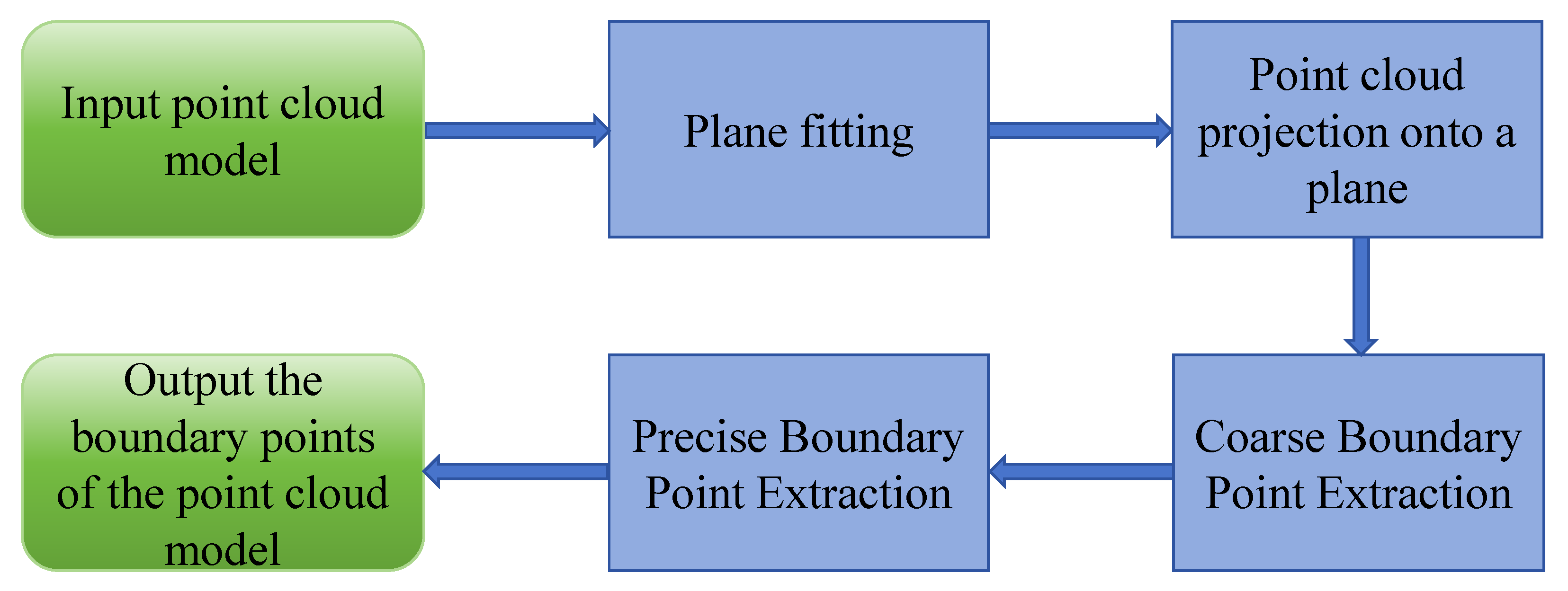
Boundary points constitute a small fraction of the overall point cloud model, and applying a complex algorithm to ascertain which points are boundary points requires considerable time. To achieve the rapid extraction of boundary points, this paper proposes an algorithm for rapidly extracting boundary points of planar building components from point clouds. The workflow of the algorithm is illustrated in Figure 1. The proposed algorithm mainly consists of three steps. The first step is plane fitting and projection. The point cloud is fitted to a plane, and all points are projected onto it to reduce the influence of outlier noise on boundary point extraction. The second step is coarse boundary point extraction. A simple and fast algorithm is utilized to extract the coarse boundary points of planar building components, retaining all true boundary points while removing most non-boundary points. The third step is precise boundary point extraction, where the true boundary points are accurately identified from the coarse boundary points.
Figure 1. Algorithm Flowchart for Extracting Boundary Points from Point Clouds.

3.1. Point Cloud Plane Fitting and Projection

This algorithm aims to extract boundary points of planar architectural components from point clouds. Outlier noise frequently exists in planar point clouds generated from building scans, necessitating preprocessing before boundary point extraction. Specifically, the point cloud undergoes planar fitting using the least squares method, followed by projection onto the fitted plane. This effectively mitigates the interference of outlier noise on subsequent boundary point extraction. The process of point cloud plane fitting and projection is as follows:
Denote the point cloud as P ( x i , y i , z i ) , with the plane equation of the point cloud given by Equation (1).
e x + f y + g z + h = 0 .
When g is not equal to zero, dividing both sides of Equation (1) by g yields Equation (2).
z = e g x f g y h g
Substituting E = e g , F = f g and G = h g into Equation (2) yields Equation (3).
z = E x + F y + G .
The distance d i from a point P ( x i , y i , z i ) to the plane is given by Equation (4). For multiple points, the total sum of squared distances is expressed by Equation (5). To determine the optimal plane, this sum of squared distances must be minimized. Since the denominator in Equation (5) is positive, the minimization is independent of the denominator, and it is sufficient to minimize the numerator q, whose expression is given in Equation (6).
d i = | E x i + F y i + G z i | E 2 + F 2 + 1
i = 1 n d i 2 = i = 1 n ( E x i + F y i + G z i ) 2 E 2 + F 2 + 1
q = i = 0 n ( E x i + F y i + G z i ) 2 .
Consider q as a quadratic multivariate function of E, F, and G. The minimum of such a multivariate function occurs at the point where all its partial derivatives vanish. Therefore, by taking the partial derivatives of q with respect to E, F, and G and setting them to zero, Equation (7) is obtained.
q E = 2 i = 1 n ( E x i + F y i + G z i ) x i = 0 q F = 2 i = 1 n ( E x i + F y i + G z i ) y i = 0 q G = 2 i = 1 n ( E x i + F y i + G z i ) = 0
By converting Equation (7) into matrix form, Equation (8) is obtained.
i = 1 n x i 2 i = 1 n x i y i i = 1 n x i i = 1 n x i y i i = 1 n y i 2 i = 1 n y i i = 1 n x i i = 1 n y i n E F G = i = 1 n x i z i i = 1 n y i z i i = 1 n z i
Solving the system of Equation (8) yields the specific values of E, F, and G, thus determining the plane equation. Substituting H = 1 into Equation (3) yields the plane Equation (9).
E x + F y + H z + G = 0 .
Let P t ( x t , y t , z t ) denote the projection of P ( x i , y i , z i ) onto the plane, with the vector P P t perpendicular to the plane, defined as P P t = ( x t x i , y t y i , z t z i ) . According to the plane equation (Equation (9)), the normal vector of the plane is n 1 = ( E , F , H ) . Since n 1 is parallel to P P t , Equation (10) is obtained.
E x t x i = F y t y i = H z t z i .
From Equation (10), the expressions for y t and z t are obtained as shown in Equations (11) and (12), respectively.
y t = F E ( x t x i ) + y i .
z t = H E ( x t x i ) + z i .
Substituting Equations (11) and (12) into Equation (9) yields Equation (13).
x t = ( F 2 + H 2 ) × x i E × ( F × y i + H × z i + G ) / ( E 2 + F 2 + H 2 )
Substituting Equation (13) into Equation (11) yields Equation (14).
y t = ( E 2 + H 2 ) × y i F × ( E × x i + H × z i + G ) / ( E 2 + F 2 + H 2 )
Substituting Equation (13) into Equation (12) yields Equation (15).
z t = ( E 2 + F 2 ) × x i H × ( E × x i + F × y i + G ) / ( E 2 + F 2 + H 2 )
The projection P t ( x t , y t , z t ) of point P i ( x i , y i , z i ) onto the plane can be computed according to Equations (13)–(15).

3.2. Extraction of Coarse Boundary Points

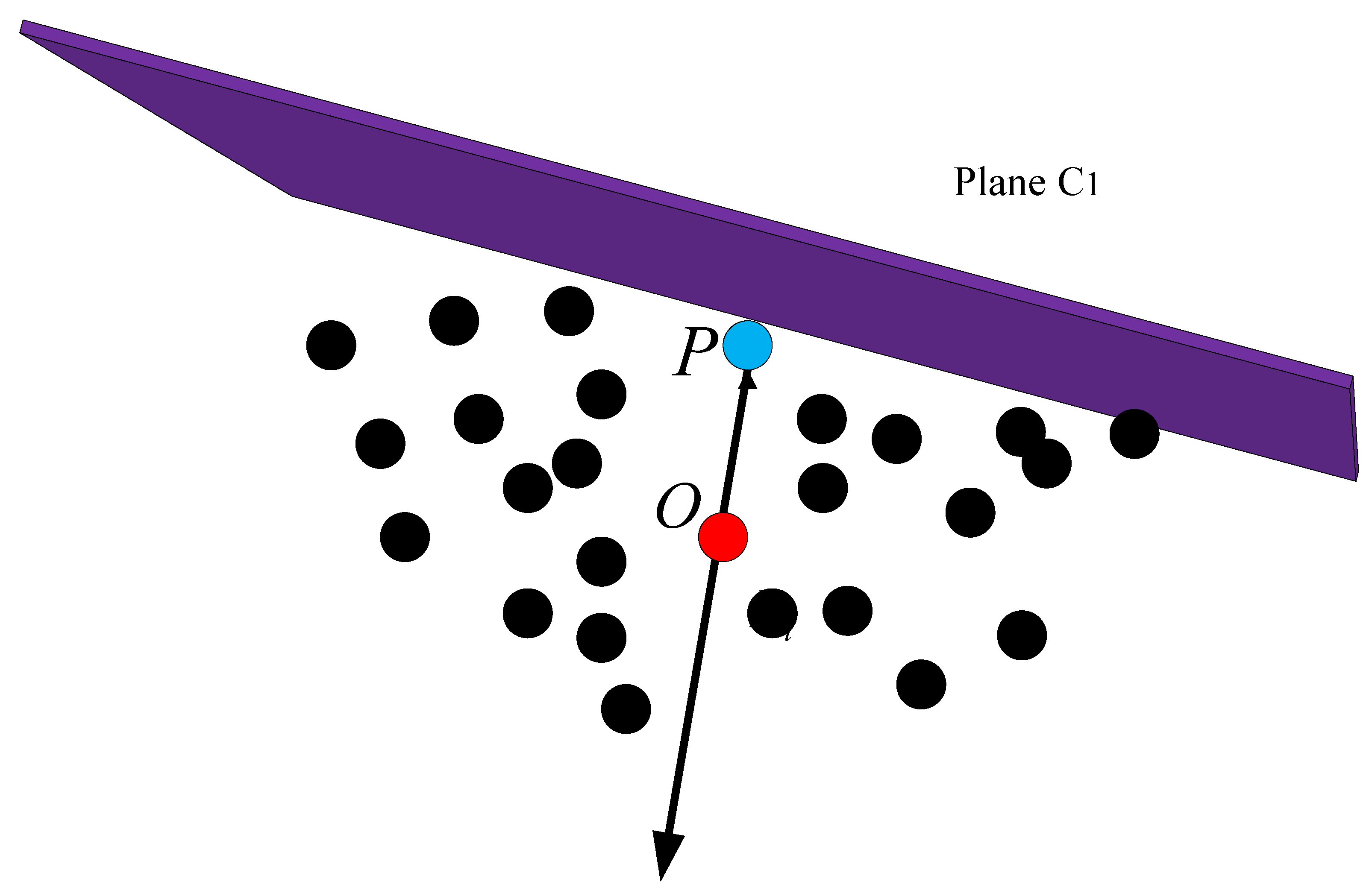
In a point cloud, the majority of points do not belong to the boundary, with only a small fraction representing boundary points. Evaluating every point in the point cloud with a complex algorithm to identify boundary points can lead to considerable computational expense. Therefore, this study first employs a coarse boundary point extraction step to rapidly eliminate most non-boundary points, retaining only potential boundary points. This approach substantially reduces the computational overhead of subsequent precise boundary point extraction. The method for extracting coarse boundary points involves constructing a plane perpendicular to the entire point cloud for each point and classifying it as a coarse boundary point based on the number of neighboring points located on one side of this plane, thereby effectively removing the majority of interior planar points. Figure 2 illustrates the plane C 1 perpendicular to the point cloud. When point P is a boundary point, all its neighborhood points lie on the same side of plane C 1 .
Figure 2. Illustration of point P and its neighborhood orthogonal to plane C 1 .
The procedure for extracting coarse boundary points is as follows:
Let a point in the point cloud be denoted as P, and the n neighboring points within radius r around P be represented as R ( p 0 , p 1 , p 2 , , p n 1 ) . Calculate the centroid O of the n neighboring points of point P using the following Equation (16).
O = 1 n i = 0 n p i .
Determine the perpendicular plane C 1 . Compute the vector P O . The plane C 1 is orthogonal to P O and passes through point P. Consequently, the normal vector n C 1 of the perpendicular plane C 1 can be computed using Equation (17).
n C 1 = P O P O .
Compute the point count on one side of plane C 1 . The vector P p n points from point P to domain point R ( p 0 , p 1 , p 2 , , p n 1 ) . Using Equation (18), the dot product between vector P p n and vector n C 1 yields the result M n . When a domain point lies on one side of the plane, M n is greater than 0. Let n u m denote the number of instances where M n is greater than 0.
M n = P p n · n C 1
Determination Method for Coarse Boundary Points. Let k denote the proportion of points on one side of plane C 1 relative to the total points in the neighborhood, with k = num n . A larger k indicates a greater number of points on one side of plane C 1 . When k exceeds a certain threshold, the point P can be regarded as a coarse boundary point. To enhance the discriminative capability of k, it is nonlinearly mapped using Equation (19) to obtain the result h 1 . This mapping amplifies the numerical differences between small and large k values, thereby enhancing the discriminability of boundary features. Let c denote the distance from point P to the centroid O of its neighboring point cloud. When point P lies in a boundary region, the value of c is typically larger. Therefore, by multiplying c with h 1 , a combined indicator h 2 is obtained, as shown in Equation (20). This indicator further amplifies the numerical differences between boundary and non-boundary points, thereby enhancing the discriminative capability of coarse boundary points.
h 1 = 1 1 + e k + 5
h 2 = h 1 × c
To determine the discriminative threshold t, the parameter k is set to 0.7, and a point is considered a potential boundary point if the proportion of points on one side of the plane within its neighborhood exceeds 0.7. Let a point cloud model consist of N points. Compute the distance from each point to the centroid of its neighboring points, and sort the distances in ascending order to obtain the sequence S = { s 1 , s 2 , s 3 , , s N } . The distance at the position corresponding to 0.7 N in the sequence is then taken as the value of c, i.e., c = s 0.7 N . Substituting k = 0.7 and c = s 0.7 N into Equations (19) and (20), the threshold t is calculated. Point P is classified as a coarse boundary point if h 2 exceeds t; otherwise, it is not considered a coarse boundary point.

3.3. Extraction of Precise Boundary Points

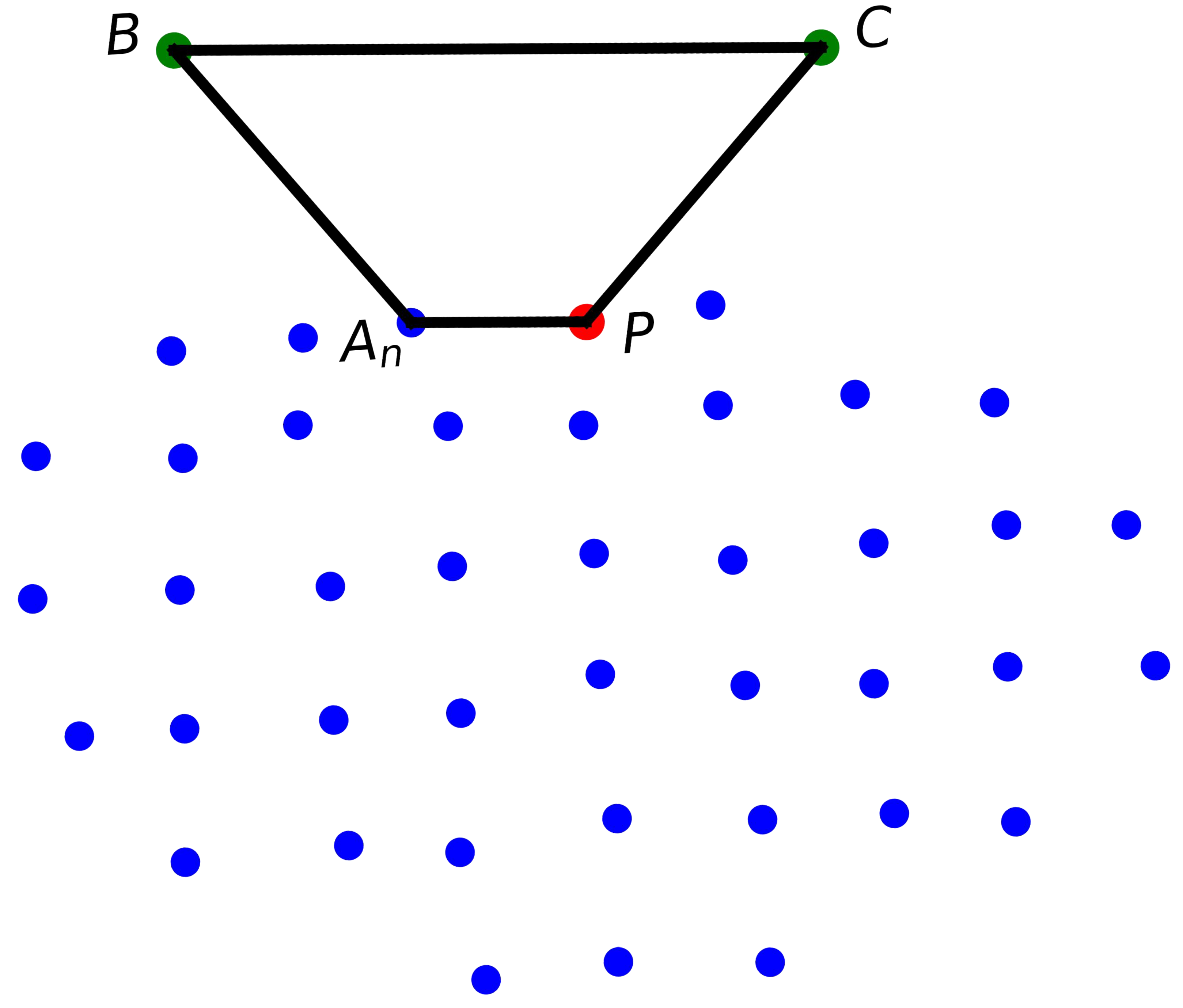
In contrast, while precise boundary point extraction methods are more complex than coarse boundary point extraction methods, they enable more accurate boundary point extraction. Since most non-boundary points have already been removed in Section 3.1, only a small number of points require complex algorithmic evaluation to extract precise boundary points. This significantly reduces the time required for boundary point extraction. The specific method for extracting precise boundary points is as follows. For each target point P within the extracted coarse boundary points, a boundary detection region is defined using its neighboring points, and P is classified as a boundary point based on the number of neighbors contained within this region. In the point cloud plane, n neighboring points of the target point P are identified within a radius r, denoted as A = { A 1 , A 2 , , A n } . Boundary detection regions are then constructed sequentially for point P using each neighbor in A. If a boundary detection region contains no neighboring points, point P is identified as a boundary point, and the construction of the remaining boundary detection regions is terminated. An example boundary detection region P A n B C constructed from point P and one of its neighboring points A n is shown in Figure 3. The following describes the method for constructing the boundary detection region P A n B C , as well as the procedure for determining whether the neighboring points of P within this region.
Figure 3. Schematic illustration of point P, its neighboring points, and the boundary detection region. In the figure, the red point represents P, the blue points represent P’s neighboring points, and the green points B and C represent points obtained through the construction of the boundary detection region P A n B C .
To more clearly illustrate the method for constructing the boundary boundary detection detection boundary detection region P A n B C , the region is drawn separately. The intersection D of the extended lines B A and C P , the midpoint I of P A , and the midpoint N of B C are marked, and a line connecting points N and D is drawn, as shown in Figure 4.
Figure 4. Schematic diagram of the constructed boundary detection region P A n B C . Point D is the intersection of the extended lines B A and C P , point I is the midpoint of P A , and point N is the midpoint of B C .
The steps for constructing the boundary detection region P A n B C , formed by point P and its neighboring point A n , are as follows:
The coordinates of midpoint I are calculated according to Equation (21).
I = P + A n 2
The length of segment I D and the coordinates of point D were calculated. As described in Section 3.1, the normal vector of the point cloud plane n 1 has been determined, oriented perpendicular to the plane and pointing upwards. The angle β and the length of I N are set, with θ defined as β 90 . The directional vector n 3 of I D is first calculated according to Equations (22) and (23), followed by the computation of the length of I D using Equation (24). The coordinates of point D are then determined from Equation (25).
n 2 = n 1 × P A n
n 3 = n 2 n 2
I D = A n I tan θ
D = I + n 3 × I D
Determine the coordinates of points B and C. The length of D B is calculated according to Equation (26). Since D C has the same length as D B , its length can also be determined. Subsequently, the coordinates of points B and C are computed from Equations (27) and (28), respectively.
D B = I D + I N cos θ
B = D + D A n D A n D B
C = D + D P D P D C
Connect points P, A n , B, and C to form the boundary detection region P A n B C .
After constructing the boundary detection region P A n B C , it is possible to determine whether the neighboring points of P lie within this region. The steps for determining whether P’s neighboring points are inside the boundary detection region are as follows:
Calculate the angle α m between vector D A m and vector D I , as well as the projection length l m of vector D A m onto vector D I . Here, A m denotes all neighboring points of P excluding point A n and D A m is the vector pointing from point D to point A m . The angle α m is computed according to Equation (29), and the projection length l m is obtained using Equation (30).
α m = arccos D A m D I D A m D I
l m = D A m ( n 3 )
If α m exceeds θ , it indicates that there are no neighboring points within the boundary detection region P A n B C , and point P is classified as a boundary point. Similarly, if α m is less than θ and l m is either less than I D or greater than D N , this also indicates the absence of neighboring points within P A n B C , and point P is again considered a boundary point. Otherwise, if all boundary detection regions constructed between point P and its neighboring points contain neighboring points, point P is classified as a non-boundary point.

4. Experimental Results and Analysis

In this section, we present the experimental results of the algorithm introduced for extracting boundary points of planar building components from point clouds, along with an analysis. Meanwhile, the proposed algorithm is evaluated against the Angle Criterion (AC) method and the Alpha Shapes (AS) method. The Angle Criterion (AC) method [,,] and the Alpha Shapes (AS) method [,,,,,,,] are classical boundary point extraction algorithms that have been widely applied to boundary point extraction in the field of point clouds [].
In the experiments, planar building components from the indoor 3D point cloud dataset S3DIS [] were used as test objects. S3DIS is a publicly available dataset released by Stanford University. All implementations were carried out on a computer equipped with 24 GB RAM and an Intel i5-12400 processor, running Windows 10, with PyCharm 2022.1.2 (Community Edition) as the development platform.

4.1. Experimental Results

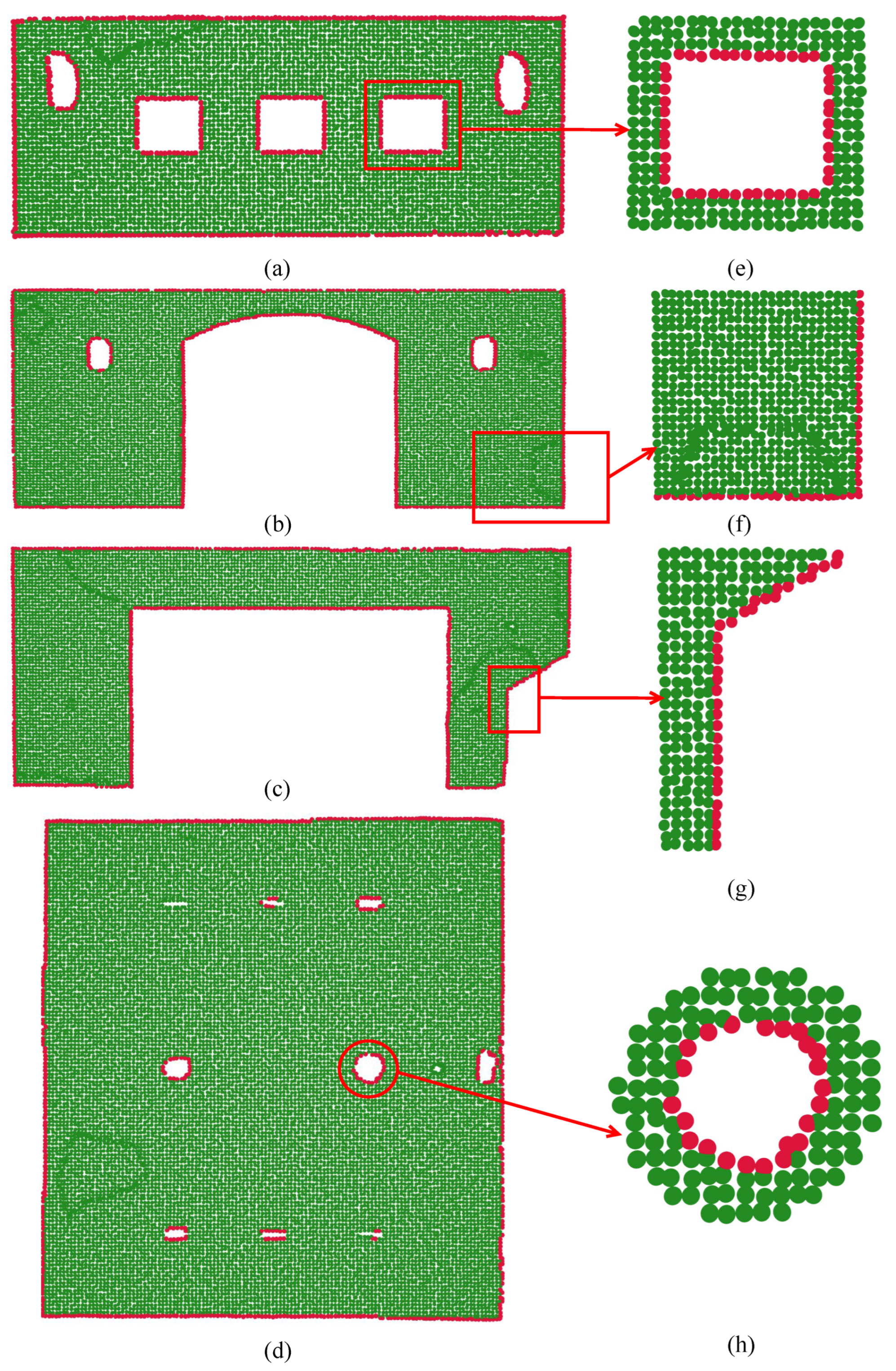
In this study, planar building components such as walls and roofs were selected from the S3DIS indoor point cloud dataset as experimental samples. Voxel downsampling was applied to the point clouds to reduce data volume. Figure 5 illustrates the outcomes of the proposed algorithm, where green markers indicate interior points of planar components and red markers correspond to boundary points. As shown in the figure, the proposed method effectively distinguishes and extracts both interior and exterior boundary points of the model, demonstrating strong performance.
Figure 5. Boundary point extraction results of the proposed algorithm on Models 1 to 4: (ad) show the boundary points extracted by the proposed algorithm for Models 1 to 4, and (eh) present the corresponding local magnified views of Models 1 to 4.
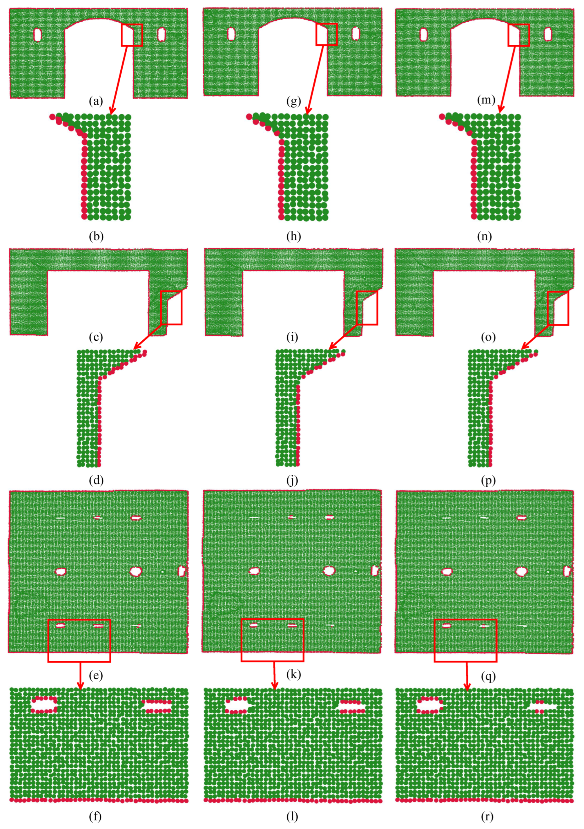
The effectiveness of the algorithm in extracting boundary points was evaluated by comparing it with the Angle Criterion (AC) and Alpha Shapes (AS) methods. Figure 6 illustrates the outcomes of boundary point extraction for the three methods on Models 1–4. The figure demonstrates that the proposed algorithm outperforms the AC and AS methods in extracting both interior and exterior boundary points from the point cloud models.
Figure 6. Boundary point extraction results for Models 2–4 using three methods. Panels (a,c,e) present the results of the proposed algorithm; (g,i,k) present the results obtained by the Angle Criterion method; and (m,o,q) present the results obtained by the Alpha Shapes method. The local magnified views are as follows: (b,d,f) correspond to (a,c,e); (h,j,l) correspond to (g,i,k); and (n,p,r) correspond to (m,o,q).

4.2. Accuracy Analysis of Boundary Point Extraction

To assess the precision and reliability of the proposed algorithm in boundary point extraction, its results are evaluated using three metrics: completeness ( C P ), correctness ( C R ), and quality (Q) []. Their calculation formulas are given in Equations (31)–(33) [].
C P = | T P | | T P | + | F N |
C R = | T P | | T P | + | F P |
Q = | T P | | T P | + | F N | + | F P |
In these metrics, T P denotes the number of actual boundary points that are correctly recognized as boundary points, F N denotes the number of actual boundary points that are incorrectly recognized as non-boundary points, and F P refers to the number of falsely extracted boundary points []. The proposed algorithm was applied to extract boundary points from Models 1 through 4, and the computed values of completeness ( C P ), correctness ( C R ), and quality (Q) [] are presented in Table 1. Across all models, the C P , C R , and Q metrics remain above 90%, confirming that the algorithm provides accurate and robust detection of boundary points within point clouds.
Table 1. Completeness ( C P ), Correctness ( C R ), and Quality (Q) of Boundary Point Extraction for Models 1–4 Using the Proposed Algorithm.
Furthermore, Table 2 presents the C P , C R and Q metrics of the Angle Criterion (AC) and Alpha Shapes (AS) methods on Models 1 and 4, alongside a comparison with the proposed algorithm. The comparison demonstrates that, relative to the other methods, the proposed algorithm achieves higher C P and Q values for Models 1 and 4, confirming its superior reliability in boundary point extraction.
Table 2. The C P , C R , and Q metrics of the three methods applied to boundary point extraction in Models 1 and 4.

4.3. Noise Resistance Analysis

To evaluate the noise-resilience of the proposed algorithm, zero-mean Gaussian noise with standard deviations of 10% and 20% of the average point distance [] was added to the point cloud models. Subsequently, boundary points were obtained from the point cloud models with varying noise levels, and the accuracy of the extracted boundary points was analyzed. Figure 7 presents the boundary point extraction outcomes of the proposed method on Model 5 under noise-free and noisy conditions. The figure illustrates that the algorithm can accurately extract the boundary points of Model 5 at different noise levels, demonstrating its strong noise-resistance capability.
Figure 7. Boundary Point Extraction Results of the Proposed Algorithm on Noise-Free and Noisy Point Clouds of Model 5. (a) Noise-free Model 5; (e,i) Model 5 with zero-mean Gaussian noise, with standard deviations of 10% and 20% of the average point spacing, respectively; (c,g,k) present the boundary points extracted from (a,e,i), respectively; (b,f,j) present the local magnified views of (a,e,i), respectively. (d,h,l) present the local magnified views of (c,g,k), respectively.
In order to quantitatively assess the noise robustness of this algorithm, the completeness ( C P ), correctness ( C R ), and quality (Q) [] of boundary point extraction from the noisy point cloud of Model 5 were computed. The corresponding results are presented in Table 3. Table 3 indicates that the completeness, correctness, and quality of extracted boundary points decrease slightly as the intensity of Gaussian noise increases, with the majority of C P , C R , and Q values remaining above 90%. These results indicate that the proposed algorithm achieves reliable and accurate boundary point extraction while showing strong resilience to noise.
Table 3. The C P , C R , and Q results for the boundary point extraction of Model 5.

4.4. Efficiency Analysis of Boundary Point Extraction

To analyze the efficiency of the proposed algorithm in extracting boundary points of planar building components from point clouds, this section presents the time (in seconds) required by the algorithm to extract the boundary points of Models 1 to 4. The extraction times of the Angle Criterion (AC) algorithm and the Alpha-Shape (AS) algorithm for Models 1 to 4 are also provided. The proposed algorithm was compared with other algorithms. As shown in Table 4, compared with the other methods, the average extraction time of the proposed algorithm is reduced by 60% compared to the Angle Criterion method and by 78% compared to the Alpha Shapes method. The proposed algorithm requires the least time, demonstrating faster execution and higher efficiency.
Table 4. Boundary point extraction times of the three methods for Models 1 to 4.

5. Conclusions

This paper proposes an algorithm for extracting boundary points of planar building components from point clouds. The algorithm performs boundary point extraction through three steps: plane fitting, coarse boundary extraction, and precise boundary point identification. Experimental results demonstrate that the proposed algorithm achieves over 90% in completeness ( C P ), correctness ( C R ), and quality (Q) when extracting boundary points of planar building components. This indicates that the algorithm can effectively extract point cloud boundary points with high accuracy and reliability. Comparative experimental results demonstrate that the proposed method achieves higher accuracy in boundary point extraction than both the Angle Criterion method and the Alpha Shapes method. In addition, the average extraction time of the proposed method is reduced by 60% compared to the Angle Criterion method and by 78% compared to the Alpha Shapes method. These experimental results indicate that the proposed method can extract the boundary points of planar building components with high accuracy while maintaining high computational efficiency, demonstrating excellent performance. However, a limitation of the present work is that the algorithm’s performance in extracting boundary points of planar building components may be affected under high-noise conditions. Future research will focus on enhancing the algorithm’s noise robustness and exploring its extension to boundary point extraction for non-planar point cloud components.

Author Contributions

Methodology, Y.H. and M.C.; Software, Y.H.; Validation, G.H.; Resources, G.H. and J.L.; Data curation, G.H. and J.L.; Writing—original draft, Y.H.; Writing—review & editing, M.C., G.H. and J.L.; Supervision, M.C. All authors have read and agreed to the published version of the manuscript.

Funding

This work was supported by the National Natural Science Foundation of China under Grants 62062015 and 61662006.

Data Availability Statement

The data used in this study are publicly available from the Stanford Large-Scale 3D Indoor Spaces (S3DIS) dataset: https://cvg-data.inf.ethz.ch/s3dis/ (accessed on 20 September 2025).

Conflicts of Interest

The authors declare no conflicts of interest.

References

  1. Chen, X.; An, Q.; Zhao, B.; Tao, W.; Lu, T.; Zhang, H.; Han, X.; Ozdemir, E. Contour Extraction of UAV Point Cloud Based on Neighborhood Geometric Features of Multi-Level Growth Plane. Drones 2024, 8, 239. [Google Scholar] [CrossRef]
  2. Su, Z.; Peng, J.; Feng, D.; Li, S.; Yuan, Y.; Zhou, G. A Building Point Cloud Extraction Algorithm in Complex Scenes. Remote Sens. 2024, 16, 1934. [Google Scholar] [CrossRef]
  3. Awrangjeb, M. Using point cloud data to identify, trace, and regularize the outlines of buildings. Int. J. Remote Sens. 2016, 37, 551–579. [Google Scholar] [CrossRef]
  4. Zong, W.; Li, M.; Li, G.; Wang, L.; Wang, L.; Zhang, F. Toward efficient and complete line segment extraction for large-scale point clouds via plane segmentation and projection. IEEE Sens. J. 2023, 23, 7217–7232. [Google Scholar] [CrossRef]
  5. Ni, H.; Lin, X.; Ning, X.; Zhang, J. Edge detection and feature line tracing in 3D-point clouds by analyzing geometric properties of neighborhoods. Remote Sens. 2016, 8, 710. [Google Scholar] [CrossRef]
  6. Lu, Z.; Baek, S.; Lee, S. Robust 3D line extraction from stereo point clouds. In Proceedings of the 2008 IEEE Conference on Robotics, Automation and Mechatronics, Chengdu, China, 21–24 September 2008; pp. 1–5. [Google Scholar]
  7. Yang, B.; Wei, Z.; Li, Q.; Li, J. Semiautomated building facade footprint extraction from mobile LiDAR point clouds. IEEE Geosci. Remote Sens. Lett. 2012, 10, 766–770. [Google Scholar] [CrossRef]
  8. Lu, X.; Liu, Y.; Li, K. Fast 3D line segment detection from unorganized point cloud. arXiv 2019, arXiv:1901.02532. [Google Scholar] [CrossRef]
  9. Lei, P.; Chen, Z.; Tao, R.; Li, J.; Hao, Y. Boundary recognition of ship planar components from point clouds based on trimmed delaunay triangulation. Comput. Aided Des. 2025, 178, 103808. [Google Scholar] [CrossRef]
  10. Yang, B.; Wei, Z.; Li, Q.; Li, J. Automated extraction of street-scene objects from mobile lidar point clouds. Int. J. Remote Sens. 2012, 33, 5839–5861. [Google Scholar] [CrossRef]
  11. Hu, Z.; Chen, C.; Yang, B.; Wang, Z.; Ma, R.; Wu, W.; Sun, W. Geometric feature enhanced line segment extraction from large-scale point clouds with hierarchical topological optimization. Int. J. Appl. Earth Obs. Geoinf. 2022, 112, 102858. [Google Scholar] [CrossRef]
  12. Sampath, A.; Shan, J. Building boundary tracing and regularization from airborne LiDAR point clouds. Photogramm. Eng. Remote Sens. 2007, 73, 805–812. [Google Scholar] [CrossRef]
  13. Pu, S.; Vosselman, G. Knowledge based reconstruction of building models from terrestrial laser scanning data. ISPRS J. Photogramm. Remote Sens. 2009, 64, 575–584. [Google Scholar] [CrossRef]
  14. Boulaassal, H.; Landes, T.; Grussenmeyer, P. Automatic extraction of planar clusters and their contours on building façades recorded by terrestrial laser scanner. Int. J. Archit. Comput. 2009, 7, 1–20. [Google Scholar] [CrossRef]
  15. Hackel, T.; Wegner, J.D.; Schindler, K. Contour detection in unstructured 3D point clouds. In Proceedings of the IEEE Conference on Computer Vision and Pattern Recognition, Las Vegas, NV, USA, 27–30 June 2016; pp. 1610–1618. [Google Scholar]
  16. Liu, K.; Ma, H.; Zhang, L.; Gao, L.; Xiang, S.; Chen, D.; Miao, Q. Building outline extraction using adaptive tracing alpha shapes and contextual topological optimization from airborne LiDAR. Autom. Constr. 2024, 160, 105321. [Google Scholar] [CrossRef]
  17. Lin, Y.; Wang, C.; Chen, B.; Zai, D.; Li, J. Facet segmentation-based line segment extraction for large-scale point clouds. IEEE Trans. Geosci. Remote Sens. 2017, 55, 4839–4854. [Google Scholar] [CrossRef]
  18. Tian, P.; Hua, X.; Tao, W.; Zhang, M. Robust Extraction of 3D Line Segment Features from Unorganized Building Point Clouds. Remote Sens. 2022, 14, 3279. [Google Scholar] [CrossRef]
  19. Bendels, G.H.; Schnabel, R.; Klein, R. Detecting Holes in Point Set Surfaces. J. WSCG 2006, 14, 89–96. [Google Scholar]
  20. Wei, J.; Wu, H.; Yue, H.; Jia, S.; Li, J.; Liu, C. Automatic extraction and reconstruction of a 3D wireframe of an indoor scene from semantic point clouds. Int. J. Digit. Earth 2023, 16, 3239–3267. [Google Scholar] [CrossRef]
  21. Dos Santos, R.C.; Pessoa, G.G.; Carrilho, A.C.; Galo, M. Automatic Building Boundary Extraction from Airborne LiDAR Data Robust to Density Variation. IEEE Geosci. Remote Sens. Lett. 2020, 19, 1–5. [Google Scholar] [CrossRef]
  22. Edelsbrunner, H.; Kirkpatrick, D.; Seidel, R. On the shape of a set of points in the plane. IEEE Trans. Inf. Theory 2003, 29, 551–559. [Google Scholar] [CrossRef]
  23. Liao, Z.; Liu, J.; Shi, G.; Meng, J. Grid partition variable step alpha shapes algorithm. Math. Probl. Eng. 2021, 2021, 9919003. [Google Scholar] [CrossRef]
  24. dos Santos, R.C.; Galo, M.; Carrilho, A.C. Extraction of building roof boundaries from LiDAR data using an adaptive alpha-shape algorithm. IEEE Geosci. Remote Sens. Lett. 2019, 16, 1289–1293. [Google Scholar] [CrossRef]
  25. Chen, X.; Yu, K. Feature line generation and regularization from point clouds. IEEE Trans. Geosci. Remote Sens. 2019, 57, 9779–9790. [Google Scholar] [CrossRef]
  26. Armeni, I.; Sener, O.; Zamir, A.R.; Jiang, H.; Brilakis, I.; Fischer, M.; Savarese, S. 3D semantic parsing of large-scale indoor spaces. In Proceedings of the IEEE Conference on Computer Vision and Pattern Recognition, Las Vegas, NV, USA, 27–30 June 2016; pp. 1534–1543. [Google Scholar]
  27. Liu, K.; Ma, H.; Zhang, L.; Liang, X.; Chen, D.; Liu, Y. Roof segmentation from airborne LiDAR using octree-based hybrid region growing and boundary neighborhood verification voting. IEEE J. Sel. Top. Appl. Earth Obs. Remote Sens. 2023, 16, 2134–2146. [Google Scholar] [CrossRef]
  28. Awrangjeb, M.; Fraser, C.S. An automatic and threshold-free performance evaluation system for building extraction techniques from airborne LIDAR data. IEEE J. Sel. Top. Appl. Earth Obs. Remote Sens. 2014, 7, 4184–4198. [Google Scholar] [CrossRef]
  29. Park, M.K.; Lee, S.J.; Lee, K.H. Multi-scale tensor voting for feature extraction from unstructured point clouds. Graph. Model. 2012, 74, 197–208. [Google Scholar] [CrossRef]
  30. Zhao, R.; Pang, M.; Zhang, Y. Robust shape extraction for automatically segmenting raw LiDAR data of outdoor scenes. Int. J. Remote Sens. 2018, 39, 9181–9205. [Google Scholar] [CrossRef]
Disclaimer/Publisher’s Note: The statements, opinions and data contained in all publications are solely those of the individual author(s) and contributor(s) and not of MDPI and/or the editor(s). MDPI and/or the editor(s) disclaim responsibility for any injury to people or property resulting from any ideas, methods, instructions or products referred to in the content.

Article Metrics

Citations

Article Access Statistics

Multiple requests from the same IP address are counted as one view.