Abstract
In this paper, virtual synchronous generator (VSG) technology is innovatively introduced into the distributor-unified power flow controller (D-UPFC) control to simulate the power generation characteristics of the synchronous generator. Concepts such as inertia and damping in the synchronous generator are introduced into power electronic equipment to provide voltage and frequency support for the system. The VSG control system, which specifically includes the virtual governor, the virtual excitation regulator, and the construction of the VSG model, is designed first. Then, the overall control combining the VSG and the series converter in D-UPFC is discussed. Finally, based on the influence of moment of inertia and damping coefficient on the response parameters, a VSG parameter adaptive control strategy based on refined fuzzy control was proposed. The simulation shows that this strategy can effectively reduce the active overshot and frequency deviation in the dynamic process of the system, eliminate secondary oscillations, and improve the dynamic response capability.
1. Introduction
The substantial access of distributed energy and the uncertainties brought by nonlinear and unbalanced loads in electricity generation and demand lead to voltage exceeding limits and feeder power imbalance problems easily occurring in current distribution networks, reducing the security and reliability of the distribution network. To solve the above problems, the Smart Soft Open Point (SOP) has emerged. SOP is a highly controllable power electronic device, used to replace traditional switching devices, achieving the regulation of active and reactive power flow during normal operation. At the same time, due to the isolation of the DC link and the instantaneous control of current, SOP can effectively promote fault isolation and power supply restoration in active distribution networks [1].
To further enhance the flexible regulation capability of power flow in distribution networks, researchers have proposed a device based on SOP, the distribution unified power flow controller (D-UPFC). The D-UPFC integrates series inverters and parallel rectifiers, which can achieve compensation for multiple power quality issues and power flow transfer [2]. The topology of the D-UPFC is shown in Figure 1. Its left and right ends are connected between 10 kV medium-voltage distribution networks. The core part consists of a series converter composed of a series transformer and a voltage source inverter (Series Converter, SEC) and a parallel converter composed of a parallel transformer and a voltage source rectifier. The two converters are interconnected via a common DC bus [2]. The parallel converter of the D-UPFC primarily provides stable DC voltage support for the system, while the series converter achieves power flow regulation by injecting voltage with adjustable magnitude and phase into the grid.
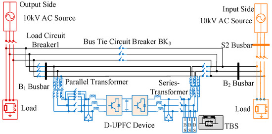
Figure 1.
Basic structure of D-UPFC.
For the problems existing in the traditional D-UPFC, current research has achieved structural simplification and performance improvement through the innovation of power electronic devices. Ref. [3] proposed a novel DC-isolated UPFC by adopting three parallel equivalent capacitors. Through the switching of power electronic switches, it realizes energy transfer and electrical isolation between series and parallel inverters, eliminating the transformer in traditional converters. A power coordination control strategy for UPFC containing energy storage units is proposed in [4]. By fixing the rated voltage of the series converter and utilizing the energy storage unit to regulate the source current, it achieves load shedding of the parallel converter, suppresses overcurrent during voltage sags, and provides full load power from the energy storage during source interruption, remarkably reducing the capacity requirement of UPFC.
At the same time, to address the issue that insufficient dynamic response capability of the power grid may cause potential security risks, the scholars have proposed introducing short-term energy storage devices into power electronic converters and improving control strategies, thereby achieving dynamic emulation of the external characteristics of synchronous generator sets, which is the VSG technology [5]. The related concepts of virtual synchronous generators are explained, classification criteria and application paradigms for VSG are established, and application methods for different functional types of VSG devices are revealed through specific engineering examples in [6]. Regarding control strategies, an interconnected converter control strategy based on VSG is designed according to the power coordination requirements of hybrid AC/DC microgrids in [7], which can provide inertia support for both AC and DC sub-microgrids. Model predictive algorithms and VSG technology are innovatively combined in [8]; through the abandonment of conventional cascaded voltage–current regulation modules, the system topology is simplified while dynamic regulation accuracy is improved. Virtual impedance is introduced into VSG control, and a transient voltage compensation mechanism is constructed through modification of the input voltage, effectively enhancing the system’s low-voltage ride-through (LVRT) capability [9]. Linear Active Disturbance Rejection Control (LADRC) technology is employed to suppress frequency oscillations caused by load fluctuations under VSG control in [10]. A nonlinear PID controller is introduced into the dual voltage–current loop, with system dynamic characteristics optimized in real time through a tracking differentiator, resulting in significant improvement of disturbance rejection performance during abrupt changes in operating conditions in [11]. An adaptive model of virtual rotational inertia is established in [12]. By utilizing boundary conditions that maintain steady-state system operation, it determines the feasible region for virtual inertia and damping coefficients. Within this feasible region, it achieves dynamic adjustment of virtual inertia and damping coefficients based on rotor angular frequency and its rate of change, and verifies the stability of the VSG system under this control method using the Lyapunov stability criterion. Nevertheless, the selection of constraint conditions is overly complex, increasing the computational burden of the system. Moreover, the linear adaptive model struggles to meet the nonlinear variation requirements of VSG parameters.
Fuzzy control has been widely recognized as an effective approach for addressing nonlinear control challenges. In [13], an adaptive control strategy for VSG parameters based on fuzzy logic was introduced. This method adaptively adjusts the inertia and damping coefficients of the VSG through fuzzification, fuzzy inference, and defuzzification processes, thereby simplifying the control computation. However, the fuzzy rules employed in [13] remain relatively simplistic, failing to fully capture the nonlinear characteristics of the VSG power–angle curve. Refs. [14,15,16] have analyzed the dynamic behavior of VSG systems under active power and frequency disturbances. These works divided the oscillation process into four intervals and proposed optimized adjustment strategies for damping and inertia in each interval. Although these methods represent a step forward, they primarily rely on the signs of the angular velocity deviation (Δω) and its rate of change (dω/dt), without accounting for the continuous variations in frequency and its derivative. This oversimplification may lead to insufficient adjustment precision and limit the control performance in practical applications. It is also noteworthy that current research on VSG technology has predominantly focused on parallel-connected converters, such as grid-forming inverters in microgrids or renewable energy integration systems [17,18]. In contrast, the application of VSG control to series-connected converters, such as those used in power flow regulation devices like the D-UPFC, remains relatively unexplored. Series-connected converters play a critical role in managing line power flow and enhancing grid stability [19]. Therefore, investigating the implementation of VSG control in series converters is essential to fully leverage its potential in improving grid support capabilities.
This paper aims to address the research gaps by introducing a refined fuzzy-control-based adaptive strategy for VSG parameters. The main contributions are summarized as follows:
- (1)
- A combination of Gaussian and triangular membership functions is adopted to enhance the sensitivity and accuracy of the fuzzification process;
- (2)
- Moving beyond the conventional four-interval division that relies solely on the signs of state variables, an eight-interval partitioning strategy is proposed for the oscillation process;
- (3)
- The proposed refined fuzzy VSG control is applied and validated on the series converter of a D-UPFC. This extends the benefits of VSG technology to flexible power flow regulation, enhancing grid support capabilities from a new perspective.
The remainder of this paper is organized as follows. Section 2 introduces the fundamentals of synchronous generators and the design of the VSG controller for series converters. Section 3 investigates the refined fuzzy adaptive strategy for optimizing key parameters of VSG. Section 4 presents the simulation results and discussion. Finally, Section 5 concludes the paper.
2. Series Converter VSG Modeling and Control System Design
2.1. Review of Synchronous Generator
The VSG control in this paper is based on salient-pole machines. Its main structure consists of two parts: the stator and the rotor. The stator part comprises three-phase stationary windings, and the rotor part integrates an excitation winding system and a damping winding system. Its physical model is shown in Figure 2.
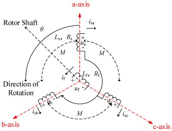
Figure 2.
Schematic diagram of a synchronous generator.
The flux linkage coupling relationships of the synchronous generator are expressed as follows:
The stator winding operates with symmetrical three-phase currents under normal conditions. The magnetic flux expression of the three-phase stator winding is obtained from Equation (1) as:
When the rotor magnetic field rotates, the magnetic flux in each phase of the armature winding changes accordingly, and the induced alternating electromotive force eabc can be expressed as:
Combining Equations (2) and (3), while considering the resistance loss of the stator winding, terminal voltage uabc of the synchronous generator follows.
The electromagnetic equations describing the internal physical characteristics of the synchronous generator are shown in Equation (4). It is unnecessary to extensively study its high-order precision dynamic model. Instead, only the second-order rotor motion equation needs to be established. The second-order mechanical equation of the synchronous generator is obtained as follows.
where J is the inherent rotational inertia; D is the damping coefficient; Pm is the mechanical power input from the prime mover; Pe is the electromagnetic power output by the synchronous generator; and ω0 is the system rated angular frequency.
2.2. VSG Control of Series Converter
By analogizing the series converter to the synchronous generator, it is known that the DC side of the converter undertakes energy support. Functionally, it can be equivalent to the prime mover system of the synchronous generator. Therefore, the DC input power Pin of the converter can be equivalent to the mechanical power Psm of the prime mover, while the output power Pout transmitted by the converter to the load through the feeder can be equivalent to the electromagnetic power Pse of the generator. Figure 3 below shows the equivalent comparison diagram of the series converter and the synchronous generator.
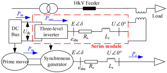
Figure 3.
Series converter and synchronous generator equivalent comparison.
Based on the theoretical foundation above, the specific implementation process of virtual synchronization control for the series converter will be elaborated next. This is mainly decoupled into three parts: the functional block model of the synchronous generator, the governor, and the excitation regulator [20,21].
2.2.1. Functional Block Model
The electromagnetic equations and mechanical equations described by Equations (4) and (5) are equivalently mapped into the control of the series converter, respectively. Its standard second-order model can be expressed as follows:
where the subscript “v” added in the variables represents “virtual” compared with Equation (5). From the perspective of control mechanism analysis, when the virtual resistance Rv is increased, it can significantly suppress high-frequency oscillations, but it will reduce the accuracy of the control loop and increase the steady-state deviation between the input and output results. Therefore, parameter optimization is required between oscillation suppression and steady-state accuracy.
The electromotive force evabc of the virtual synchronous generator can be expressed as:
where E represents the input voltage of the VSG.
Based on Equations (6) and (7), the functional block model of VSG control can be established in Figure 4.
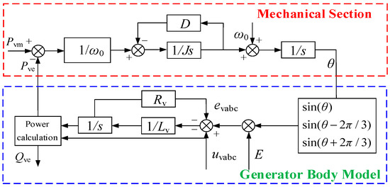
Figure 4.
VSG functional block model.
2.2.2. Virtual Governor Controller Model
The virtual governor realizes the dynamic response and regulation of power grid frequency fluctuations by replicating the droop frequency regulation characteristic of a synchronous generating unit. Its dynamic regulation process follows the synchronous generator power–frequency characteristic curve shown in Figure 5.
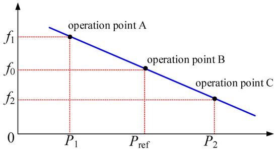
Figure 5.
Synchronous generator power–frequency characteristic curve.
As can be seen from Figure 5, the frequency of the synchronous generator decreases as its output power increases. This power–frequency regulation characteristic is described by Equation (8).
where Rsw is the frequency droop coefficient of the governor and ksw is the active power–frequency regulation coefficient of the synchronous generator.
When regulating the system frequency, the virtual governor needs to adjust the input mechanical power accordingly:
where Pref is the active power reference of the VSG, ∆P is the active power–frequency deviation of the VSG, Pvm is the input mechanical power of the VSG, and kω is the active power–frequency regulation coefficient of VSG.
The active power–frequency regulation coefficient reflects a damping characteristic in the VSG control system, which serves to buffer frequency variations. It is usually a fixed value. The active frequency control under off-grid operation is shown in Figure 6.
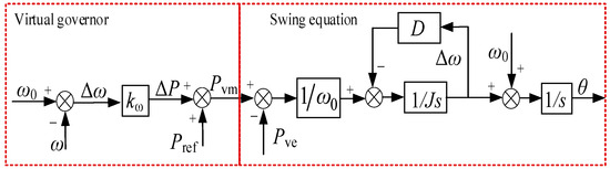
Figure 6.
Virtual governor control block diagram.
As can be seen from Figure 6, the virtual governor equation and the swing equation are as follows:
Combining the two equations in Equation (10), the open-loop transfer function of the system can be obtained as follows.
where and .
As can be seen from Figure 6 and Equation (11), when the virtual governor is incorporated into the swing equation of the synchronous generator, the output frequency response is the first-order inertial response (). It means that the introduction of the virtual governor has added an equivalent inertia link to the droop control. When the grid frequency is disturbed, it can buffer the frequency variation of the system, provide inertia support for the system, and actively participate in the frequency regulation of the system.
2.2.3. Virtual Excitation Regulator Controller Model
The virtual excitation regulator equips the converter with reactive power–voltage regulation characteristics. As is shown in the reactive power–voltage droop characteristic curve in Figure 7, the system voltage decreases as the reactive power increases. The control relationship is expressed as:
where ksq is the reactive power–voltage regulation coefficient of the synchronous generator.
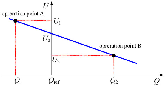
Figure 7.
Reactive power–voltage characteristic curve.
Based on the reactive power–voltage characteristic curve of the synchronous motor (Figure 7), a virtual excitation regulator control is designed. By real-time monitoring of the system’s operating status, when reactive power imbalance occurs in the power system, the generator terminal voltage will deviate from the set reference value. At this point, the excitation controller generates a regulation command based on the collected voltage deviation, dynamically adjusting the current and potential values of the rotor winding. Furthermore, the induced electromotive force and port voltage of the synchronous generator are changed to ensure that the grid voltage operates stably within the rated range, achieving dynamic compensation and balance maintenance of reactive power in the AC system. The control block diagram of the virtual excitation regulator is shown in Figure 8.
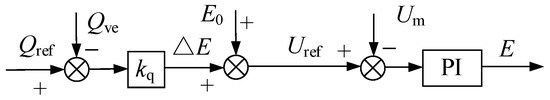
Figure 8.
Virtual excitation regulator control block diagram.
The reactive power–voltage regulation characteristic endowed to the converter by the virtual exciter enables it to actively participate in voltage regulation during sudden changes in reactive power. According to Figure 8, the virtual electromotive force amplitude under VSG control can be expressed as:
The overall control block diagram for constructing VSG control algorithm can be obtained, as illustrated in Figure 9.
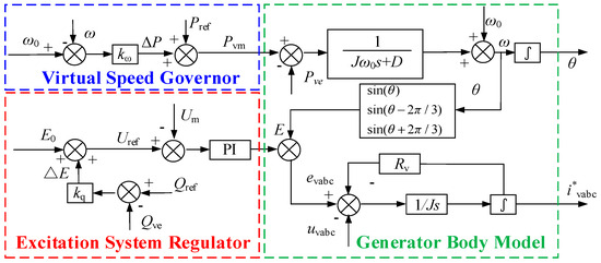
Figure 9.
VSG control algorithm.
By combining the equivalent model of the series-type converter with the complete VSG control block diagram, the overall control block diagram of the series-type converter integrated with VSG can be obtained, as shown in Figure 10. The control achieves decoupling control through current closed-loop regulation and ultimately realizes VSG control of the series converter via SVPWM modulation.
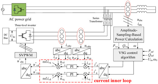
Figure 10.
Series converter VSG overall control block diagram.
3. Adaptive Strategy of VSG Parameters Based on Refined Fuzzy Control
When subjected to external power impact or large load fluctuation, it is necessary to optimize the control parameters of the VSG during oscillation to avoid phenomena such as frequency exceeding the limit during oscillation and power impact damaging the converter [22]. The core purpose of introducing fuzzy control into the VSG control is to solve the inherent contradiction that its fixed control parameters cannot balance stability and rapidity under complex and variable working conditions. The fuzzy controller can dynamically and adaptively adjust key parameters such as moment of inertia and damping coefficient, enhancing system stability under large disturbances and improving response speed under small deviations.
3.1. Influence of Adjustable Parameters on Output Characteristics
The main adjustable parameters include rotational inertia J and damping coefficient D, and their influence on output characteristics is reflected in the variation in active power and angular frequency.
Equation (6) is transformed into torque form, as shown in Equation (14).
where ω0 is the rated angular velocity of the VSG; Tm, Te, and TD are the mechanical torque, electromagnetic torque, and damping torque of the VSG, respectively.
The output power of the VSG is obtained as shown in Equation (15).
where U is the load-side voltage value; Z is the impedance of the VSG filter circuit; δ is the power angle of the VSG; and θ is the impedance angle of the filter circuit. Using the small-signal model analysis method of synchronous generators in traditional power systems, assuming that the resistance of the VSG is 0, an approximation is obtained: θ ≈ π/2; δ ≈ 0 and, substituting into Equation (14), we get:
If taking 0 < ζ < 1 and the error is within ±5%, then the overshoot σ% and the settling time ts of the second-order system are:
From Equation (17), it can be seen that the dynamic performance of the VSG second-order system is mainly determined by J, D, and kω. In engineering practice, kω is usually a fixed value. When either D or J is constant, the overshoot σ% and settling time ts are proportional to J and inversely proportional to D. The rotational inertia J determines the oscillation frequency during the active power output dynamic response of the VSG, while the damping coefficient D determines the attenuation rate of the power oscillation.
The dynamic response changes of the system’s output active power from 0 to 100 kW under different moments of inertia and damping coefficients are shown in Figure 11.
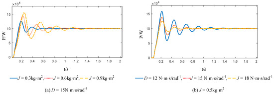
Figure 11.
Dynamic response of output active power under different moments of inertia and damping coefficients.
According to Equation (14), we have:
Assuming is constant, then the larger D is, the smaller the frequency deviation will be. Assuming is constant, the larger J is, the smaller the rate of change of angular velocity will be. Therefore, in order to maintain a stable system frequency, and can be suppressed by appropriately increasing the damping coefficient d and the moment of inertia J.
The variation in the frequency characteristics of the system output under different moments of inertia and damping coefficients is shown in Figure 12.
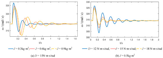
Figure 12.
Dynamic response of output angular velocity under different moments of inertia and damping coefficients.
3.2. Dynamic Performance Analysis of VSG
The dynamic performance of the VSG can be characterized by the system power angle and angular velocity trajectory curve as shown in Figure 13. At the initial operating point A, the rotor angular velocity ω is synchronized with the rated angular velocity ωN of the grid. When the system is subjected to external disturbance and the active power increases to P2, the original equilibrium is broken. Under the combined action of virtual inertia and damping, the system undergoes oscillation over multiple cycles and finally converges to a new equilibrium point B. This nonlinear transition constitutes the typical dynamic response process of the VSG.
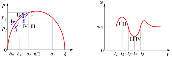
Figure 13.
VSG power angle and angular velocity oscillation curve.
The trajectory curve can be divided into four parts:
Stage I: Sudden increase in system input power causes an increase in virtual rotor speed, moving from point A to B.
Stage II: Output power is greater than input power, causing virtual rotor deceleration, but the rotor speed is still greater than the system speed; when reaching point c, the angular velocity is synchronized and, under the influence of output power, continues to decrease.
Stage III: Output power is greater than input power, resulting in continuous decrease in angular velocity.
Stage IV: Output power is less than input power, and virtual rotor angular velocity gradually approaches steady-state value.
This cyclic energy exchange forms attenuated oscillation in the virtual inertia-damping system, finally stabilizing the system at the target operating point B, reconstructing power balance.
3.3. Design of Refined Fuzzy Adaptive Controller for VSG Parameters
3.3.1. Virtual Parameter Adjustment Rules
Traditional fuzzy control methods typically divide the oscillation process of angular velocity into four regions [13], based on the sign of angular velocity deviation (Δω) and the rate of change of angular velocity (dω/dt), to determine the adjustment rules for virtual inertia (ΔJ) and damping coefficient (ΔD). The control strategy is as follows:
Region I: dω/dt > 0 and Δω > 0. The angular velocity is deviating from the steady state and increasing. Increase ΔJ to suppress the angular velocity change.
Region II: dω/dt < 0 and Δω > 0. The angular velocity is still above the steady state but starts to decrease. Decrease ΔJ and increase ΔD to accelerate the return to steady state.
Region III: dω/dt < 0 and Δω < 0. The angular velocity is below the steady state and continues to drop. Increase ΔJ to suppress further deviation.
Region IV: dω/dt > 0 and Δω < 0. The angular velocity is recovering. Decrease ΔJ and increase ΔD to facilitate a quicker recovery.
These form the basic control strategy under four-interval fuzzy control, as shown in Table 1.

Table 1.
Four-interval fuzzy control parameter adjustment rule.
The conventional four-interval strategy, which relies solely on the signs of Δω and dω/dt, offers a basic framework but lacks the precision to capture continuous dynamic variations. To achieve finer-grained control over the system’s kinetic energy and damping dissipation, we refine the oscillation process into eight intervals, as shown in Figure 14. This granularity enables a superior strategy: (1) distinguishing between strong acceleration and early deceleration for proactive inertia management; (2) implementing a “soft landing” by tapering off parameter adjustments near the setpoint to suppress secondary oscillations effectively. This approach facilitates more precise coordination between virtual inertia and damping. The refined adjustment rules are detailed as follows.
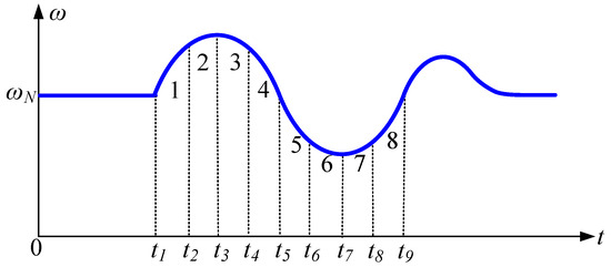
Figure 14.
Eight interval angular frequency oscillation curve.
In Interval 1(t1–t2), the angular frequency deviation Δω > 0 and the angular frequency change rate dω/dt > 0. At this time, the angular frequency gradually exceeds the rated value. The virtual inertia J should be increased to suppress dω/dt and slow down the growth of the angular frequency.
In Interval 2(t2–t3), the angular frequency deviation is over zero. At this time, dω/dt has already gradually decreased. The increment of virtual inertia J should be relatively reduced compared to the change in Interval 1(t1–t2). This can both suppress the change in angular frequency and prepare in advance for the reduction in virtual inertia. Simultaneously, in Intervals 1(t1–t2) and 2(t2–t3), the damping coefficient D should be controlled to increase as Δω increases to suppress the frequency oscillation and deviation caused by the increase in J.
In Interval 3(t3–t4), the angular frequency deviation Δω > 0 and the angular frequency change rate dω/dt < 0. Within this interval, the angular frequency gradually decreases until it returns to the steady-state value. At this time, the virtual inertia J should be decreased to reduce the system inertia and accelerate the change in angular frequency.
In Interval 4(t4–t5), the angular frequency deviation Δω > 0 and the angular frequency change rate dω/dt < 0 but, at this time, the angular frequency has already tended towards the steady-state value. At this time, the reduction amount of virtual inertia J should be appropriately decreased. This is both beneficial for the recovery of angular frequency and can prevent the next oscillation triggered by excessively fast inertia reduction. Simultaneously, in Intervals 3 (t3–t4) and 4 (t4–t5), the increase amount of the damping coefficient D should be appropriately lowered. This can both suppress angular frequency oscillation and avoid the increase in regulation time caused by an excessively large D value.
The adjustment rules for Intervals 5 (t5–t6) and 6 (t6–t7), Intervals 1 (t1–t2) and 2 (t2–t3), Intervals 7 (t7–t8) and 8 (t8–t9), and Intervals 3 (t3–t4) and 4 (t4–t5) are the same and therefore are not repeated. From this, the refined rules table for parameter adjustment during the VSG oscillation process shown in Table 2 can be obtained.
Table 2.
Refined fuzzy adaptive parameter adjustment rule table.
3.3.2. The Struct of Refined Fuzzy Adaptive Controller
The refined fuzzy controller mainly consists of fuzzification, refined fuzzy control rules, and defuzzification, as illustrated in Figure 15. Here, ke and kec are the input scaling factors, while kJ and kD are the output scaling factors.
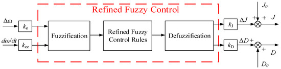
Figure 15.
Struct of refined fuzzy adaptive controller.
The input scaling factors ke and kec determine the system’s operating range and the normalized domain [−1, 1] of the fuzzy controller. The frequency fluctuation range of the power grid is usually ±0.5 Hz, corresponding to an angular frequency deviation of ±3.14 rad/s. Therefore, the normalization factor ke is equal to 1/3 = 0.33. The rate of change in angular frequency is usually ±100 rad/s2. Therefore, the normalization factor kec is equal to 1/100 = 0.01. These values ensure that the input variable is evenly distributed within [−1, 1], avoiding the membership of certain regions being too low. The output scaling factors kJ and kD are set based on the steady-state value of J and D.
The factors ke and kec are used to normalize the inputs Δω and dω/dt to the range of [−1, 1]. The values of kJ and kD are selected within a reasonable range based on regulation needs.
First, fuzzification refers to converting the controller input-angular frequency deviation Δω and its rate of change dω/dt into fuzzy variables. The input and output ranges are set within [−1, 1], and Δω and dω/dt are scaled using the input scaling factors to ensure standardization. The Δω represents system energy imbalance and dω/dt reflects inertial response speed. They exhibit distinct dynamic characteristics during VSG oscillations. To balance computational efficiency and dynamic sensitivity, we adopted hybrid membership functions. Gaussian functions avoid abrupt control actions under large disturbances (preserving VSG stability), and triangular functions ensure precise adjustments near steady state (minimizing frequency/overshoot deviations).
Both input and output variables are divided into seven fuzzy levels: {Negative Big (NB), Negative Medium (NM), Negative Small (NS), Zero (ZO), Positive Small (PS), Positive Medium (PM), and Positive Big (PB)}. The membership functions for input and output variables are shown in Figure 16.
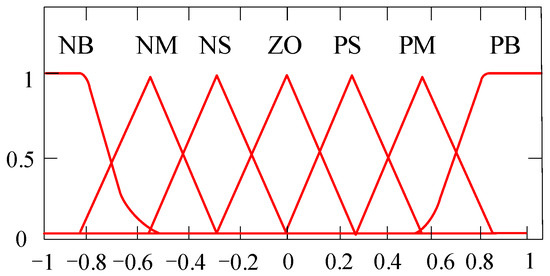
Figure 16.
Input–output membership function.
Next is the refined fuzzy control rule stage. Based on the refined virtual parameter adjustment rules designed in Table 2 and combined with the input and output membership functions, the refined fuzzy inference rule tables for control parameters are created, as shown in Table 3 and Table 4.
Table 3.
ΔJ fuzzy rule table.
Table 4.
ΔD fuzzy rule table.
Finally, defuzzification is performed using the centroid method. The resulting crisp output values are scaled using the output scaling factors kJ and kD and then superimposed on the steady-state values J0 and D0 to obtain the final adaptive adjustment values. The resulting fuzzy inference surfaces are shown in Figure 17.
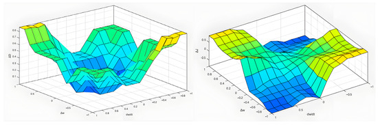
Figure 17.
Fuzzy inference result.
4. Simulink Results
4.1. D-UPFC Validation
To fully verify the effectiveness of D-UPFC in power quality management, a simulation model for the flexible interconnection scenario of a medium-voltage distribution network is established as shown in Figure 1 and the simulation parameters are tabulated in Table 5.
Table 5.
Simulation parameters.
Case 1: harmonic control
The load on the rectifier side is replaced with a nonlinear load (as a harmonic generator) and the harmonic current is suppressed by injecting compensation current on the rectifier side. At 0.075 s, the rectifier side injects compensation current into the power grid. Taking the current of phase A of the power grid as an example, the simulation results are shown in Figure 18.
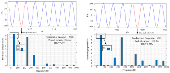
Figure 18.
Simulation results of harmonic control.
As can be seen from Figure 18, before adding the compensation current, the THD of A-phase current is 9.26%. After adding the compensation current, at 0.075 s, the THD of A-phase current is 1.04%. The high-order harmonics and current spikes of the power grid current are significantly suppressed.
Case 2: unbalanced current treatment control
The load on the rectifier side is replaced by a three-phase unbalanced load to generate a three-phase unbalanced current. Compensation current is injected into the power grid on the rectifier side for compensation. The compensation control is activated at 0.075 s. The simulation results are shown in Figure 19.
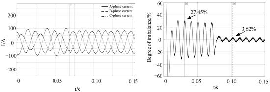
Figure 19.
Simulation results of unbalanced current treatment control.
Take the D-axis current and divide the negative sequence current component by the positive sequence current component to obtain the result of the three-phase maximum unbalance degree. As shown in the Figure 19, the maximum unbalance degree of the three phases was 27.45% before 0.075 s, and it became 3.62% after the compensation current was added at 0.075 s, verifying the effectiveness of the D-UPFC.
4.2. VSG Validation
To verify the active power transfer capability of the VSG algorithm through the series side of the system, a scenario is simulated in which 1.7 MW of active power is transferred via the interconnection switch at 0.2 s. A comparison is made between conventional vector control and the proposed VSG control, focusing on the power waveform during the switching process.
The comparison in Figure 20 shows that, after the switch closes at 0.2 s, the conventional vector-controlled converter responds quickly but exhibits a larger overshoot compared to the VSG-controlled converter, which has a slower response due to its inertia and damping characteristics. Figure 21 shows the frequency variation of the receiving-end grid under both control strategies during power flow transfer.
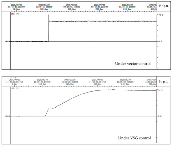
Figure 20.
Active power transfer under vector control.
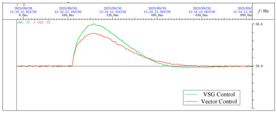
Figure 21.
Frequency of receiving-end power grid under two control modes.
After issuing the active power command, the frequency of the receiving-end grid fluctuates. Under VSG control, the converter can actively participate in frequency regulation, reducing oscillations and accelerating frequency recovery.
In another simulation scenario, load fluctuation is introduced. The system is initially set to provide 1 MW of active power and, between 1.2 s and 2.5 s, an additional 0.6 MW load is added at the receiving-end grid. The frequency and converter output power changes during this period are observed.
Figure 22 shows that, under a 0.6 MW load variation, the receiving-end grid experiences an active power imbalance. Under conventional vector control, the grid frequency drops rapidly to 49.8 Hz, and the converter output remains unchanged, contributing nothing to frequency regulation. In contrast, under VSG control, the frequency decreases more gradually and stabilizes at 49.88 Hz, with the converter supplying an additional 0.24 MW of active power to help offset the power deficit in the grid.
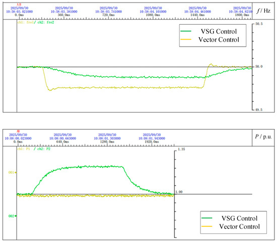
Figure 22.
Frequency and active power output of receiving-end power grid under two control modes.
4.3. Refined Fuzzy Control Validation
To verify the feasibility and superiority of the refined fuzzy control method applied to the dynamic regulation process of a series converter, a VSG parameter regulation module based on refined fuzzy control was added on the basis of the VSG control algorithm. Using Matlab 2023a, the dynamic process of the system is compared under fixed parameter control, traditional parameter linear adaptive control, four-interval fuzzy control, and refined fuzzy adaptive control. The basic simulation parameters of the system refer to the simulation settings in the previous sections, and other simulation parameters are listed in Table 6.
Table 6.
Supplementary simulation parameters for precision fuzzy control systems.
In Figure 23, the converter’s initial output active power was set to 1 MW, and the system reached stability after 1 s. At 1.2 s, the reference active power was adjusted to 1.7 MW. First, the variations in the VSG system’s virtual inertia J and damping coefficient D under different control strategies after 1.2 s were observed.
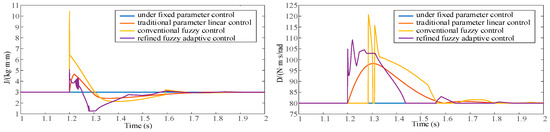
Figure 23.
J and D variation trends under different control strategies during active power changes.
From the figures above, it can be seen that the system’s virtual inertia and damping coefficient vary under different control strategies, all following the previously described control rules. The different control strategies regulate the system’s power and frequency dynamics by adjusting J and D.
A comparative analysis was conducted on the changes in active power and frequency of the dynamic system under fixed parameter control, traditional linear adaptive control, four-interval fuzzy control, and refined fuzzy adaptive control.
In Figure 24, the maximum active power overshoot under fixed parameter control reached 4.7%, 2.5% under traditional adaptive control, and 1.9% under four-interval fuzzy control, while, under refined fuzzy control, the overshoot was only 0.20%, which was nearly negligible. In addition, the maximum frequency deviation under fixed parameters was 0.356 Hz, 0.315 Hz under traditional adaptive control, 0.293 Hz under four-interval fuzzy control, and 0.259 Hz under refined fuzzy control. Moreover, observing the system frequency variation, the refined fuzzy control strategy effectively reduced the decrease in J in the defined Interval 4, thereby reducing the occurrence of second oscillation compared to four-interval fuzzy control and making frequency variation smoother. The simulation demonstrates that the proposed refined fuzzy control strategy effectively improves the dynamic performance of the VSG and reduces the frequency deviation of the system.
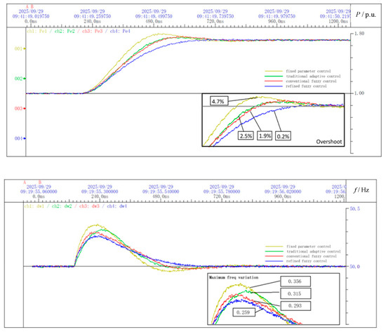
Figure 24.
Comparison of active power and frequency variation during dynamic processes.
Although the proposed improved fuzzy VSG control strategy demonstrated superior performance in the studied scenarios, it also had certain limitations.
First, it analyzes and assumes a three-phase symmetrical system. The performance under conditions of significant asymmetry deserves further study.
Secondly, the robustness of the controller was verified within the typical range of network parameters. However, if it is applied to systems with extremely different network parameters (for example, line impedance), its performance may not be optimal and the control parameters need to be readjusted.
In addition, the control strategy proposed in this paper focuses on improving the dynamic response performance of the system and its robustness to the perturbation of system parameters and achieving the frequency support function. For severe fault situations, it must be integrated with a dedicated fault ride-through solution.
5. Conclusions
This paper proposes an improved fuzzy-control-based parameter adaptive strategy for VSG and applies it to the control of the series converter in a D-UPFC. By designing refined fuzzy rules to dynamically adjust the virtual inertia and damping coefficient, the proposed strategy effectively reduces active power overshoot and frequency deviation during system transients while suppressing secondary oscillations. Simulation results demonstrate that, compared with conventional control methods, the proposed approach significantly enhances the dynamic response capability and frequency support performance of the system and provides a novel solution for improving the stability of distribution networks.
Author Contributions
Conceptualization, X.M. and X.L.; methodology, X.M. and W.C.; software, X.M.; validation, X.M. and X.L.; formal analysis, X.M. and W.C.; investigation, X.M.; resources, W.C.; data curation, X.L.; writing—original draft preparation, X.M.; writing—review and editing, X.M. and X.L.; visualization, W.C.; supervision, W.C.; project administration, X.M., W.C., and X.L.; guidance and oversight, W.C. and X.L. All authors have read and agreed to the published version of the manuscript.
Funding
This research was funded by Science and Technology Project of State Grid Corporation under Task 5400-202318551A-3-2-ZN, grant number SGJSSZ00KJJ-S2312931.
Data Availability Statement
Data are contained within the article.
Conflicts of Interest
The authors declare no conflicts of interest.
References
- Zheng, T.; Wang, Y.; Ma, J.; Tang, Z.; Li, H. Novel positive-sequence fault component directional element based on fuzzy logic for UPFC line. Autom. Electr. Power Syst. 2020, 44, 145–152. [Google Scholar]
- Wang, Q.; Yi, J.; Liu, L.; Sun, H.; Tang, Y. Optimized design of novel unified power flow controller based on DC-side energy storage. Proc. CSEE 2015, 35, 4371–4378. [Google Scholar]
- Wang, J. Research on Stability Control of UPFC/BESS Integrated into Large-Scale Renewable Energy System. Master’s Thesis, North China Electric Power University, Beijing, China, 2018. [Google Scholar]
- Huang, X.; Fan, Z.; Miao, S.; Xu, D.; Lv, W.; Ma, Z. Power coordinated control strategy for unified power quality conditioner with energy storage unit. High Volt. Eng. 2018, 44, 3390–3398. [Google Scholar]
- Yang, H.; Cai, Y.; Qu, Z.; Deng, Y.; Lu, Y.; Zhao, R. Key technologies and development trends of flexible switching equipment in distribution networks. Autom. Electr. Power Syst. 2018, 42, 153–165. [Google Scholar]
- Zhou, S. Research on Control Strategy of T-Type Three-Level Inverter. Master’s Thesis, Huazhong University of Science and Technology, Wuhan, China, 2023. [Google Scholar]
- Tang, X. Interpretation of ‘Guide for medium and low voltage DC distribution voltage’. Autom. Electr. Power Syst. 2020, 44, 23. [Google Scholar]
- T/CEC 167—2018; Technical Requirements for Interconnection Between DC and AC Distribution Networks. China Standards Press: Beijing, China, 2018.
- Sun, Y.; Zhang, J.; Zhou, J.; Shi, G.; Yang, X.; Cai, X. Multi-port flexible interconnection switch for AC/DC hybrid distribution networks. Proc. CSEE 2022, 42, 62–71. [Google Scholar]
- Feng, X.; Zhang, J.; Zhou, J.; Zhang, Y.; Shi, G.; Cai, X.; Wang, P. Series-parallel multi-port flexible interconnection switch for distribution network. Proc. CSEE 2022, 42, 6599–6611. [Google Scholar]
- Wei, Z.; Luo, Y.; Zeng, Y.; Zhao, B.; Cui, K.; Li, H.; Shi, J. Technical scheme design for flexible interconnection demonstration project of medium-voltage distribution network. Electr. Power Constr. 2022, 43, 1–11. [Google Scholar]
- Pereda, J.; Green, T.C. Direct modular multilevel converter with six branches for flexible distribution networks. IEEE Trans. Power Deliv. 2016, 31, 1728–1737. [Google Scholar] [CrossRef]
- Zhang, G.; Pei, W.; Shen, L.; Li, N.; Deng, W. Delta-connected AC/AC converter for three-port flexible interconnection in distribution network. Autom. Electr. Power Syst. 2021, 45, 32–40. [Google Scholar]
- Wang, F.; Zhang, L.; Feng, X.; Guo, H. An Adaptive Control Strategy for Virtual Synchronous Generator. IEEE Trans. Ind. Appl. 2018, 54, 5124–5133. [Google Scholar] [CrossRef]
- Li, D.; Zhu, Q.; Lin, S.; Bian, X.Y. A Self-Adaptive Inertia and Damping Combination Control of VSG to Support Frequency Stability. IEEE Trans. Energy Convers. 2017, 32, 397–398. [Google Scholar] [CrossRef]
- Jin, N.; Jia, K.; Guo, L.; Wu, Z. Virtual Synchronous Generator Parameter Adaptive Adjustment Model. In Proceedings of the 2023 IEEE International Conference on Predictive Control of Electrical Drives and Power Electronics (PRECEDE), Wuhan, China, 16–19 June 2023. [Google Scholar]
- Tian, Y.; Xu, X.; Wang, Y.; Li, Z.; Zhang, Z.; Gao, Y. Full-State Feedback Power Decoupling Control for Grid Forming Converter with Improved Stability and Inertia Response. IEEE Trans. Power Electron. 2025, 40, 2930–2942. [Google Scholar] [CrossRef]
- Lin, Q.; Uno, H.; Ogawa, K.; Kanekiyo, Y.; Shijo, T.; Arai, J.; Matsuda, T.; Yamashita, D.; Otani, K. Field Demonstration of Parallel Operation of Virtual Synchronous Controlled Grid-Forming Inverters and a Diesel Synchronous Generator in a Microgrid. IEEE Access 2022, 10, 39095–39107. [Google Scholar] [CrossRef]
- Zhang, J.; Shao, S.; Li, Y.; Zhang, J.; Sheng, K. A Voltage Balancing Method for Series-Connected Power Devices in an LLC Resonant Converter. IEEE Trans. Power Electron. 2021, 36, 3628–3632. [Google Scholar] [CrossRef]
- Wang, S.; Jing, L.; Wu, X.; Li, J.; Tian, R. Virtual synchronous characteristic analysis of unified power quality conditioner in new energy power plants. Power Syst. Technol. 2020, 44, 159–167. [Google Scholar] [CrossRef]
- Wen, Y.; Dai, Y.; Bi, D.; Guo, R.; Peng, Z. A grid-friendly control strategy for PV-storage distributed generation. Proc. CSEE 2017, 37, 464–476. [Google Scholar]
- Huang, Z.; Liu, Z.; Shen, G.; Li, K.; Song, Y.; Su, B. A virtual synchronous generator-based control strategy and pre-synchronization method for a four-leg inverter under unbalanced loads. Symmetry 2024, 16, 1116. [Google Scholar] [CrossRef]


Disclaimer/Publisher’s Note: The statements, opinions and data contained in all publications are solely those of the individual author(s) and contributor(s) and not of MDPI and/or the editor(s). MDPI and/or the editor(s) disclaim responsibility for any injury to people or property resulting from any ideas, methods, instructions or products referred to in the content. |
© 2025 by the authors. Licensee MDPI, Basel, Switzerland. This article is an open access article distributed under the terms and conditions of the Creative Commons Attribution (CC BY) license (https://creativecommons.org/licenses/by/4.0/).