Article

Reconfigurable Intelligent Surface-Assisted Antenna Design with Enhanced Beam Steering and Performance Benchmarking

by
Mustafa Adnan Abed
* and
Osman Nuri Uçan
Electrical and Computer Engineering, Institute of Graduate Studies, Altinbas University, İstanbul 34217, Turkey
*
Author to whom correspondence should be addressed.
Electronics 2025, 14(20), 4039; https://doi.org/10.3390/electronics14204039
Submission received: 23 August 2025 / Revised: 30 September 2025 / Accepted: 9 October 2025 / Published: 14 October 2025

Abstract

This paper presents a high-gain wide-band planar antenna with a Reconfigurable Intelligent Surface (RIS) for modern wireless communication applications. The antenna consists of two main parts, a basic antenna part with cross-line slots and two light-dependent resistor switches, and a second part based on the RIS layer for beam steering. The RIS is constructed from 5 × 5-unit cells with two sides, forming a square geometry. The antenna substrate is a dielectric layer of FR4 epoxy glass with a thickness of 1.6 mm. The RIS inclusions are designed and tested numerically to achieve the desired electromagnetic properties at the frequency band of interest. The fabricated prototype shows a wide band covering frequencies from 0.9 GHz to 3.5 GHz with S11 below −10 dB, achieving an antenna gain varying from 10.5 dBi up to 16.8 dBi. Experimental measurements show effective aperture usage in all configurations, and beam steering from +22° to −22° is accomplished without degrading side-lobe levels. The proposed antenna performance is tested against real-world measurements to evaluate channel performance in terms of bit error rate (BER) and channel capacity (CC). The proposed LDR-controlled design achieves compact beam steering with minimal insertion loss, unlike conventional RIS-assisted antennas that rely on PIN or varactor switches.

1. Introduction

Reconfigurable Intelligent Surfaces (RISs) have recently emerged as a transformative paradigm for shaping wireless environments, enabling programmable control of electromagnetic (EM) wave propagation through arrays of tunable subwavelength unit cells. RISs are seen as a key technology for 5G, 6G, and Internet of Things (IoT) networks because they offer energy-efficient, low-cost alternatives to active relays and traditional phased arrays [1,2,3]. A lot of people in both academia and industry are interested in them because they can improve coverage, spectral efficiency, and energy use.
The first examples of RISs were based on programmable metasurfaces and varactor/PIN-based switching [4,5,6]. They showed how to control basic reflection. These implementations worked well, but they often had problems with complicated hardware and higher insertion loss. More advanced designs brought in surfaces inspired by metamaterials and the ability to change the phase of a beam to control its polarization and steer it [7,8]. At the same time, foundational studies set the theoretical limits, practical models, and design rules for wireless systems that use RISs [9,10,11,12]. For instance, the authors in [3] measured the level at which RISs are better than decode-and-forward relays, and in [11], they made useful phase-shift models for real-world RIS beamforming.
Simultaneously, security and robustness issues in RIS-assisted communication have been examined. In [13,14], authors examined RIS applications for physical-layer security and multi-user MIMO optimization, respectively. Artificial intelligence (AI) has also become important. For example, deep learning and reinforcement learning techniques have been used for beamforming, channel estimation, and adaptive optimization of RIS-assisted systems [15,16]. Recent surveys and tutorials [17,18] have offered extensive summaries, emphasizing the capability of AI-enabled RISs to attain real-time adaptation in dynamic settings.
There are still some big problems, even with these improvements. Most cutting-edge RIS designs either need a lot of space [7], depend on complicated biasing networks [4,5], or only focus on EM characterization without testing the whole system using communication performance metrics like bit error rate (BER) and channel capacity (CC). Also, while there have been reports of RIS-enabled compact designs [7,19], support for circular polarization and hardware simplification are often not mentioned. Recent studies on energy efficiency [19] and security [20] have underscored the necessity for integrated RIS-assisted antenna designs that harmonize compactness, reconfigurability, and communication-level benchmarking.
Later, recent research focused on specific functionality with prototypes. Authors in [21] applied genetic algorithms to improve rectenna designs for hybrid energy harvesting, while authors in [20] used machine learning to recognize abnormalities in RF biosensors. The development of 5G antennas using slotted, parasitic, tapered slot, and reconfigurable fractal designs yielded significant contributions in [22,23,24], while authors in [25] examined graphene-based metasurfaces for optical beam steering. In [26], Ku-band CRLH MTMs were investigated for V2X applications. In [27], a wideband amplifying RIS architecture was proposed for 5G applications. In [28], the authors provided a comprehensive prototype and experimental validation of RIS-based wireless systems within the RIS-specific area. The issue of dual-band shared-aperture systems with autonomous control for sub-6 GHz and mmWave bands was addressed in [29]. In [30], reconfigurable antennas were presented, including beam steering and variable beamwidth, enabling adaptive coverage in fluctuating wireless settings. Based on these advancements, the current literature continues to exhibit many deficiencies. Many solutions either have little influence on communication parameters such as BER and CC, emphasize restricted bandwidths, or lack precise control over beam steering angles. In general, RISs are a revolutionary technology for 5G/6G and beyond, allowing programmable control of electromagnetic propagation through subwavelength passive or semi-active elements [31]. RISs can dynamically steer, focus, or scatter incident waves to improve coverage, energy efficiency, and physical-layer security [32]. Early implementations focused on millimeter-wave bands and large planar arrays, often using varactor diodes or PIN switches to tune reflection phase [33]. Recent studies have extended RIS concepts to sub-GHz operation, supporting long-range IoT and low-band 5G applications. The study highlights advancements in hardware-implemented MIMO and adaptive beamforming for 5G/6G systems [32]. Real-time direct digital synthesis phase-locked-loop (DDS-PLL) beam-steering architectures and switched-line phase shifters, tunable RF front-ends, and hybrid analog–digital precoding are used to achieve fast, low-latency phase control across wide bandwidths. These solutions provide deterministic control of radiation patterns and can complement AI-based strategies by providing real-time beam updates or initial steering vectors [33]. The proposed RIS unit cell can be integrated with AI-driven controllers and establish adaptive beamforming hardware to realize full MIMO capabilities in next-generation wireless networks.
This paper proposes a compact (173 × 173 mm2) RIS-assisted antenna with LDR-based reconfiguration to improve beam steering and circular polarization performance in response to these challenges. The proposed design does away with complicated biasing while keeping low insertion loss, which is different from standard PIN/varactor methods. Also, the antenna’s performance is checked against system-level metrics like BER and CC, which makes sure that it works in real-world communication situations. Comparative benchmarking against existing works validates the proposed antenna’s advantages in compactness, beam steering range, and system-level efficiency. The antenna design details are discussed in Section 2. The design methodology is explored in Section 3. In Section 4, the experimental validations are realized. The paper is concluded in Section 5.

2. Antenna Design and Geometrical Details

The proposed antenna system combines a dual-layer RIS with a truncated rectangular patch antenna to improve beam steering and directivity in modern wireless communication systems as shown in Figure 1. Corner truncations introduce orthogonal current components, while middle slots perturb surface current distribution and a centrally located cross-shaped slot fine-tunes the axial ratio response. The radiating element is based on a traditional rectangular microstrip patch but has undergone extensive modifications to optimize circular polarization and band-width performance.
The patch is mounted on an FR4 substrate with a relative permittivity of 4.4, a thickness of 1.6 mm, and a loss tangent of tan δ = 0.02. A complete copper ground plane is printed on the underside of the substrate to mitigate back lobes and ensure steady radiation patterns. The suggested RIS structure, positioned at 1 mm above the patch, significantly enhances beam steering and directivity without necessitating complex active phase shifters.
The RIS consists of two mechanically aligned layers on the identical FR4 substrate. The upper layer comprises concentric square metallic structures, while the inferior RIS layer comprises split-ring resonators (SRRs) enclosed inside a square framework. Each SRR is associated with a pair of LDR switches that dynamically adjust the reflection phase by modifying the resonant behavior of the SRRs under different illumination conditions. This optically controlled switching technology offers a cost-effective, bias-free, and EMI-resistant control solution by removing the intricacies associated with traditional PIN diodes or varactor-based RIS systems.
The proposed antenna uses unequal corner truncations to excite two orthogonal modes for circular polarization, resulting in a gain enhancement of over 90% during beam steering. The use of RIS-based beam steering reduces the BER from 1 × 10⁻² to under 1 × 10⁻⁴ at the same SNR, improving error resilience. Communication performance is analyzed using MATLAB r2014a simulations, showing that beam steering results near 25% increase effective CC under identical bandwidth and SNR conditions. The design employs economical FR4 instead of expensive low-loss laminates or complex multi-substrate stacking, offering superior compactness, expanded impedance bandwidth, enhanced realized gain, and a more stable axial ratio during steering.

3. Design Methodology

This study focuses on designing an antenna using parametric analysis, analyzing performance in terms of S11 and gain spectra numerically. The proposed antenna uses numerical parametric optimization instead of a closed-form analytical framework to capture complex mode interactions and polarization behavior. It incorporates a metasurface layer and asymmetric corner truncations, creating a highly coupled electromagnetic environment. Initial patch dimensions were set using a standard microstrip-cavity approximation. A systematic 3-D parametric sweep was conducted to identify the combination that yields the required 90° modal phase shift for circular polarization while maintaining high efficiency.

3.1. Antenna Performance Without RIS Inclusions

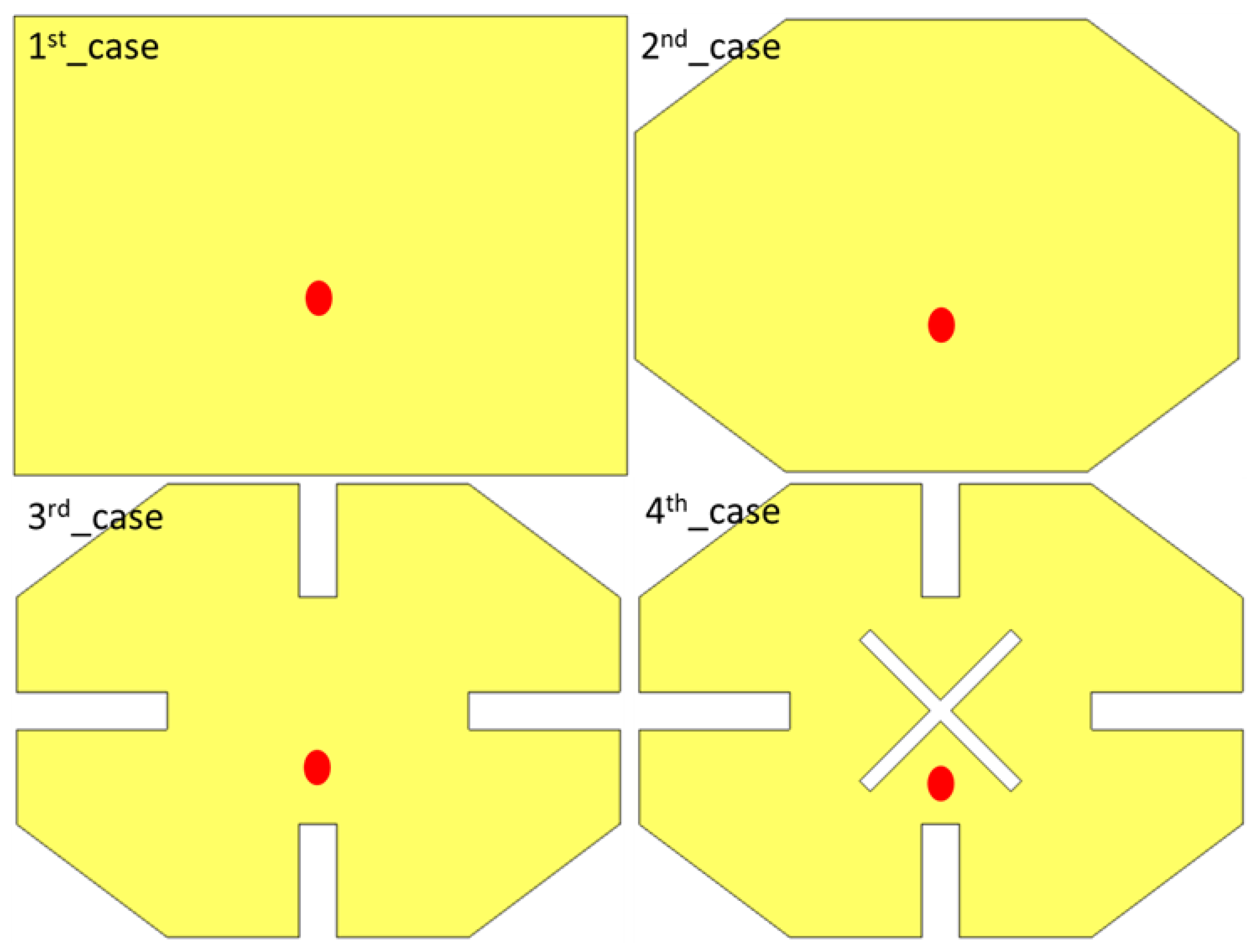
The authors conducted an analysis of antenna design without a proposed RIS layer, focusing on optimizing patch performance to meet desired requirements. They used a rectangular patch as the first case, followed by truncation etching to the patch corners as the second case, slots to the antenna patch as the third case, and cross lines as the fourth case. Images of each case are shown in Figure 2, which shows four configurations of structural modifications designed to isolate individual electromagnetic effects. Case 1 establishes the fundamental TM10 resonance near 0.915 GHz, Case 2 introduces single-corner truncation to perturb the TM01 mode, Case 3 applies unequal multiple truncations to achieve the 90° phase shift, and Case 4 adds a metasurface layer and feed optimization to broaden the impedance/axial ratio bandwidth and enhance gain.
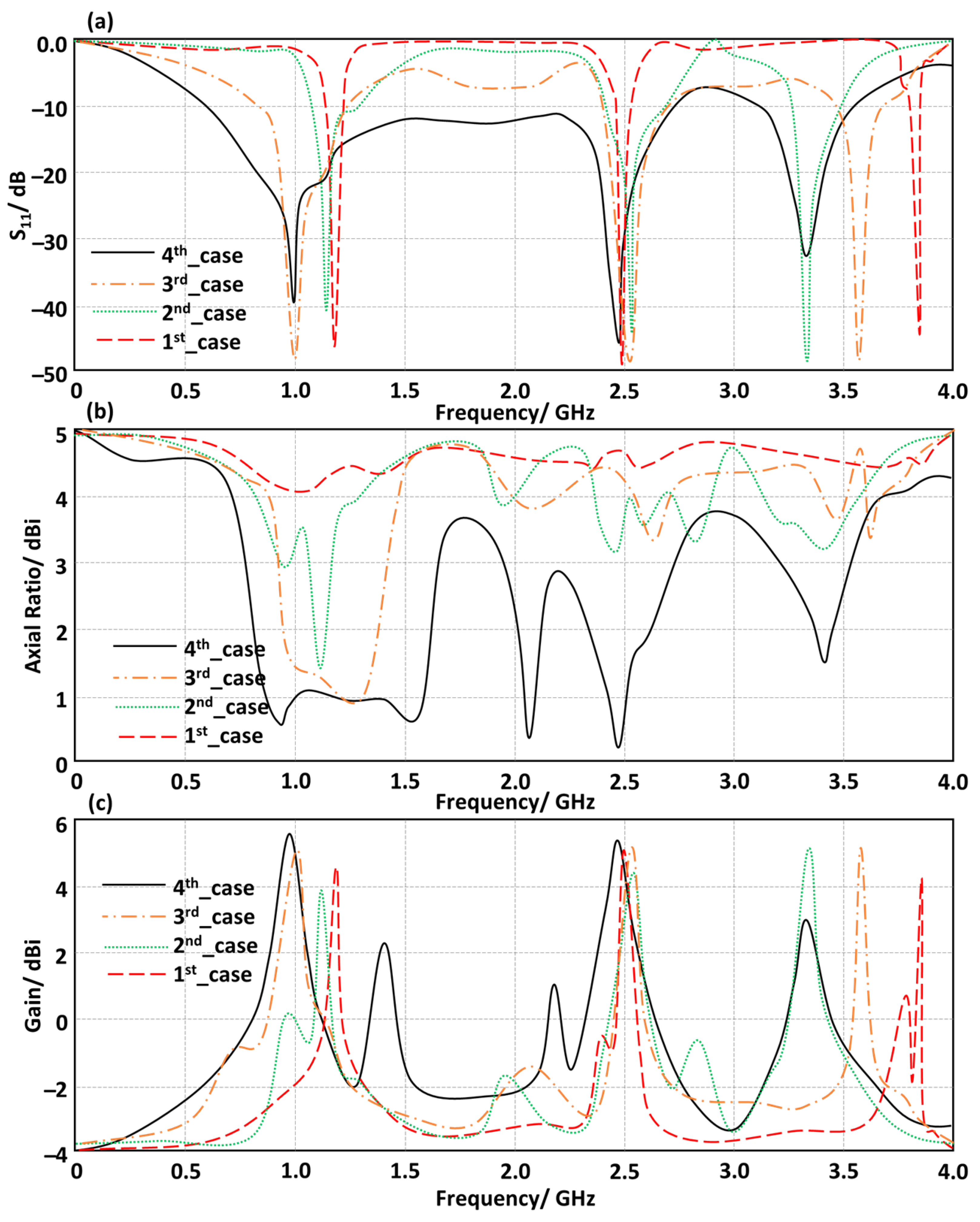
The antenna based on the 4th case achieved optimal performance in terms of bandwidth, polarization, and gain as seen in Figure 3. It achieved a bandwidth from 0.9 GHz to 2.7 GHz, with excellent circular polarization below −3 dBi and gain above 5 dBi. Another frequency band covered frequencies from 3.2 GHz to 3.6 GHz with gain around 5.5 dBi without circular polarization achievement. The antenna performance improvement is due to a sequenced evolution of the radiating structure. The initial rectangular patch supports the fundamental TM10 mode, providing linear polarization with a narrow impedance bandwidth. Unequal corner truncations generate circular polarization and enlarge the matched band, lowering the TM01 mode to couple with nearly equal magnitude and a 90° phase difference. A narrow slot is inserted along the patch diagonal, reducing the overall quality factor and expanding the impedance bandwidth. A thin parasitic strip is added to shape the radiation aperture and stabilize the broadside gain pattern. Full-wave simulations show that each step contributes a measurable improvement, with unequal corner cuts yielding a 40% axial ratio bandwidth increase, slot insertion adding 12% to the impedance bandwidth, and optimized feed with partial ground providing an additional 6% bandwidth extension.

3.2. RIS Design and Analysis

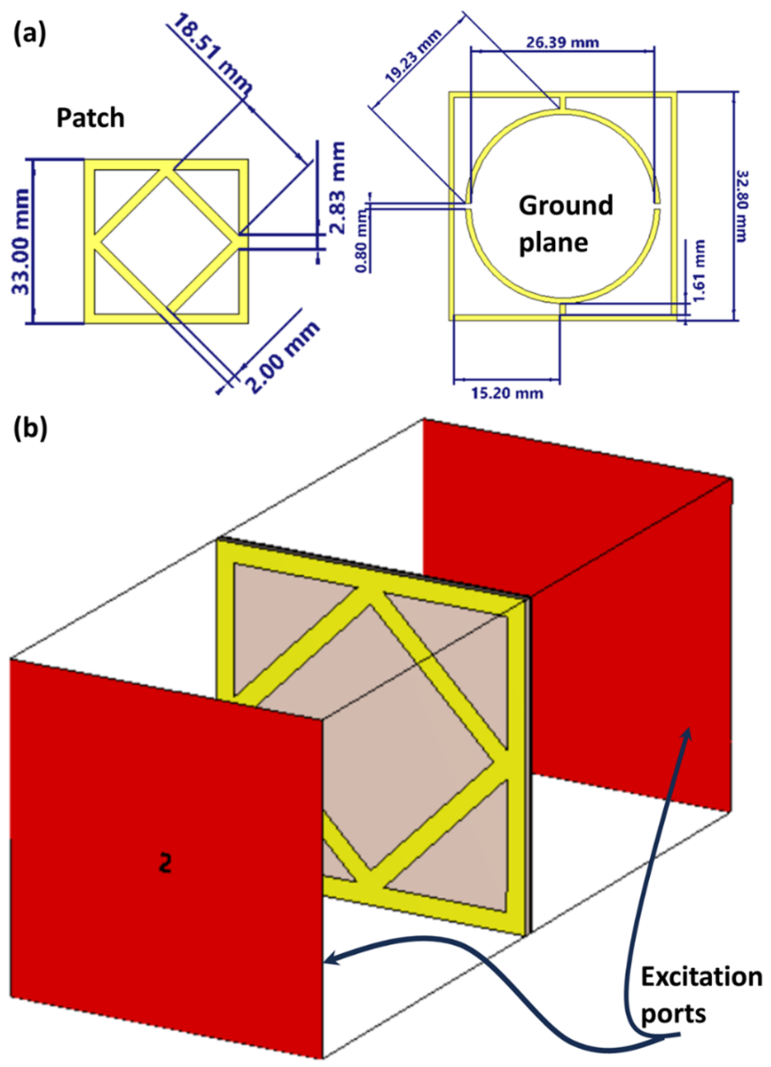
The proposed RIS unit cell is a combination of two structures, a patch and a ground plane, which improves performance. It is characterized by retrieving the relative refractive index from the simulations of S-parameters. The electromagnetic simulation model extracts the effective refractive index of the RIS unit cell. As shown in Figure 4, the boundary conditions are a perfect electric conductor along the x-axis and a perfect magnetic conductor along the z-axis [16,17]. The electromagnetic properties of the unit cell are accurately characterized using a Floquet mode analysis within the CST Microwave Studio environment. This method models an infinite, perfectly periodic array of the unit cell, providing fundamental properties like refractive index, dispersion behavior, and reflection/transmission phase and amplitude. The results are crucial for designing and optimizing the unit cell’s resonant behavior and dynamic tuning capability. The full antenna system performance is obtained through a separate full-wave simulation of the entire finite system, including the complete 5 × 5 RIS array integrated with the driven antenna patch, a finite ground plane, and the SMA feed port.
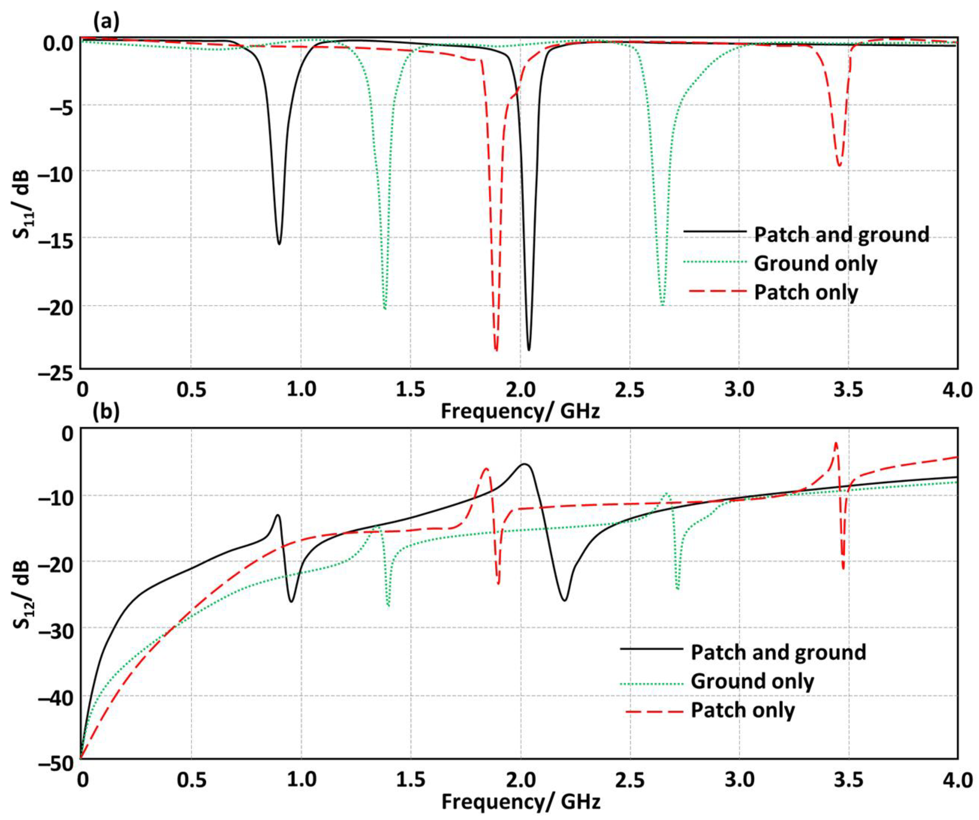
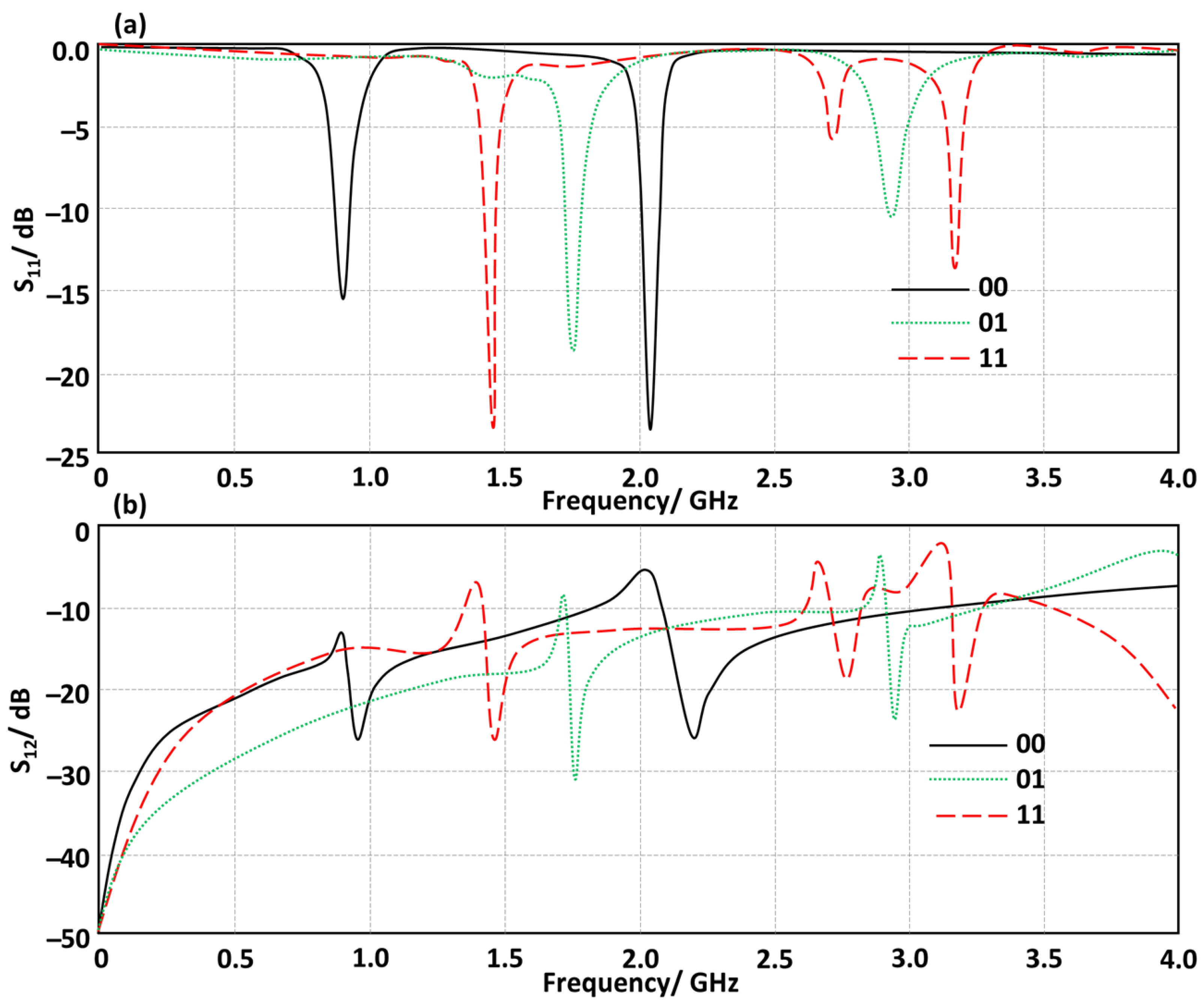
The proposed antenna system operates on the principles of structured electromagnetic resonance and near-field reactive coupling, utilizing a RIS that functions as a driven, lossy Fabry–Pérot cavity [14]. The RIS consists of two metallic layers: a patterned patch and a continuous ground plane, forming partially reflective boundaries that confine the dielectric substrate. The design leads to two distinct resonant frequencies at 0.915 GHz and 2.05 GHz—see Figure 5a—resulting from the geometric patterning of the upper patch, which tailors the effective capacitance and inductance and defines the structure’s resonant properties. These resonances facilitate a significant transformation in input impedance, enabling conjugate matching to free space over a narrow bandwidth and minimizing reflection to ensure optimal coupling of incident energy into cavity modes. This energy is subsequently re-radiated, evident in the transmission parameter S12 peaks, as shown in Figure 5b. Moreover, sharp dips in S12 indicate the presence of an electromagnetic bandgap, where surface wave propagation is prohibited, thus diminishing parasitic surface wave modes that can impair antenna performance. The dual-band resonance is leveraged for beam shaping through dynamic phase alterations of the RIS unit cells.
The proposed RIS unit cell’s electromagnetic response is influenced by LDR switching states (00, 01, and 11). These switches change RIS impedance, affecting transmission and reflection properties as depicted in Figure 6. The depth of reflection dips and resonant frequencies are modified by each switching state, with 11 states shifting nulls due to increased electrical connectivity. Conversely, the 00 state shows deep nulls at specific frequencies, indicating strong interference from resonant modes. Diode biasing affects transmission attenuation, with reduced junction resistance promoting coupling and high-impedance gaps suppressing specific propagating modes. Maxwell equations can be used to interpret these behaviors as changes in boundary conditions that alter the distributions of electric and magnetic fields, altering energy balances. The metasurface may sustain various resonant modes, some electric dipolar and some magnetic, affecting the excitation of these modes. This controlled spectral behavior allows the unit cell to work adaptively across multiple frequency bands or block unwanted interference in RIS applications. The proposed RIS reconfigurability is controlled by optically controlled switches using light-dependent resistors (LDRs), which act as variable resistors set by external illumination. When illuminated, LDRs close SRR gaps, producing a second resonant state with a distinct reflection phase.

3.3. Effects of RIS Introduction

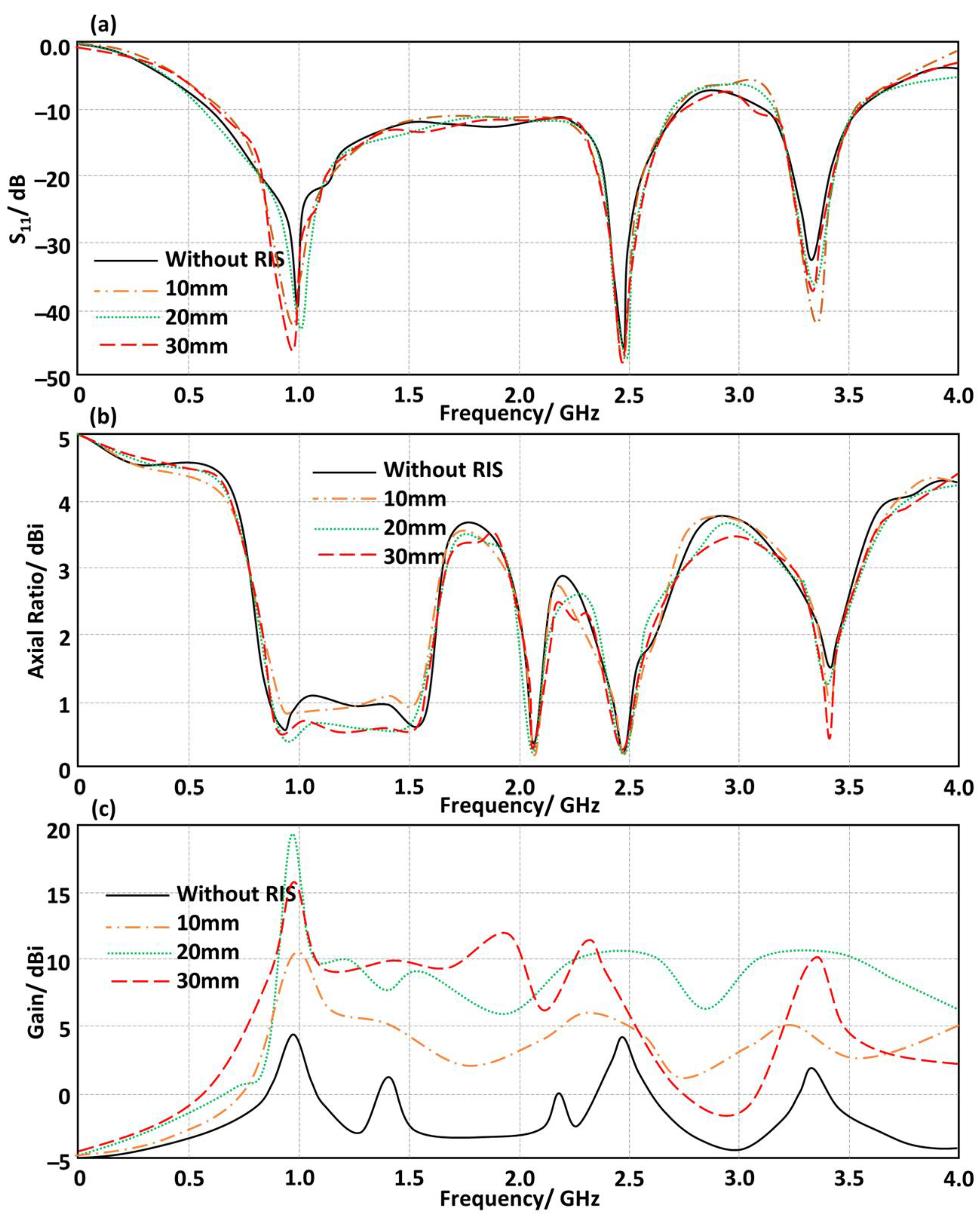
The proposed RIS layer significantly impacts the realized gain at 0.915 GHz, reaching 16.8 dBi as shown in Figure 7. This behavior is due to near-field coupling effects and classical electromagnetic aperture theory. The RIS layer, composed of engineered subwavelength unit cells, modifies the phase front of the incident field from the antenna by imposing a spatially varying reflection phase. When positioned at 20 mm, the RIS produces a coherent beamforming effect, where the reflected fields constructively interfere with the directly radiated fields in the desired direction. The RIS acts as a reactive boundary, modifying boundary conditions for both electric and magnetic field components, increasing aperture efficiency without the need for extra active elements. The axial ratio spectrum suggests that the RIS reflection phase supply is symmetric with respect to antenna polarization, maintaining relative phase and amplitude. The optimal spacing is related to the growth of the Fresnel region phase, where the RIS acts as a lens-like phase compensator, concentrating the wavefront to a smaller beamwidth and making it more direct.
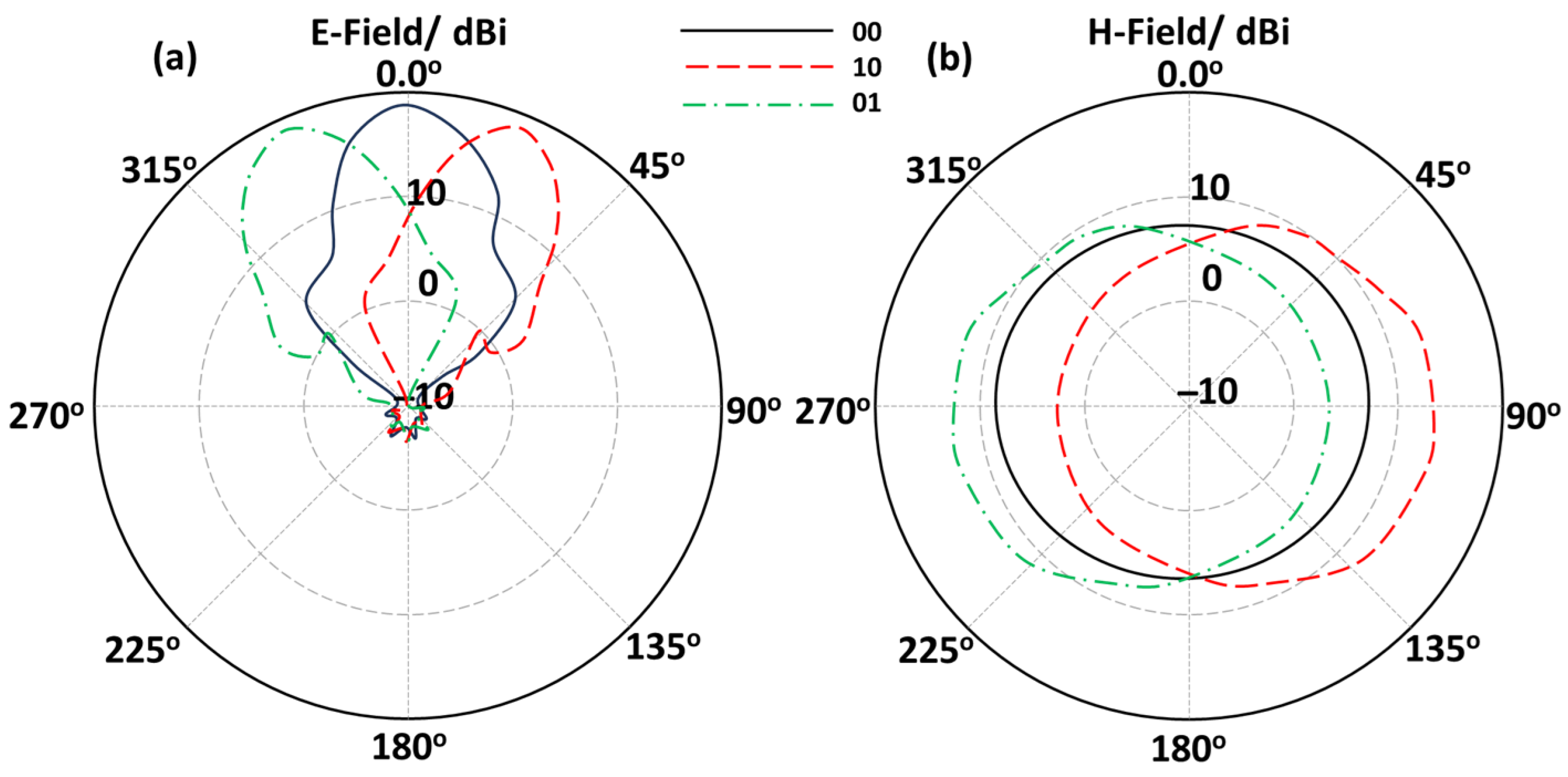
The principles of electromagnetic phase-gradient control and array theory elucidate the beam steering behavior seen in Figure 8, where the primary lobe transitions from +22° to −22° upon activating the LDR on the proposed RIS layer. The unit cells in the RIS layer create different reflection phase shifts depending on the state of the LDR. This technique makes the RIS layer act as a passive phased surface. The proposed unit cell effective surface impedance changes dynamically with changing LDR switching configurations. Based on this, the local reflection phase φ(x,y) across the proposed RIS is modified directly. From the aperture field perspective, the Farfield radiation pattern is fundamentally added to each other with Fourier transformation [3]. When a uniform gradient is added to the phase distribution throughout the RIS, the transverse wave vector changes with the direction of the primary beam according to Snell’s law:
sin θ r = sin θ i + λ 2 π d d x
In the discussed equation, dx and represent the phase gradient from switched LDR states, with a positive gradient directing the beam one way (+22°) and an inverted gradient the opposite way (−22°). This behavior parallels phased antenna arrays that alter beam direction by adjusting each element’s excitation phase. In the proposed RIS scenario, LDR switching changes the reflection phase passively, affecting reactive loading and resonance states in each cell. By modulating the energy stored versus radiated, the phase of the re-radiated wavefront is adjusted. The steering range depends on the physical aperture size and the phase swing capacity of RIS elements, achieving nearly 360° phase control with measured ±22° steering. The RIS maintains a constant amplitude response during these phase gradient changes, ensuring no distortion or gain loss in steering, thus enhancing gain and directionality for smart beamforming in communication systems. The gain variation in the proposed MTS-based antenna reflects its loading, as it couples to the patch radiator. This two-dimensional periodic array of subwavelength unit cells creates a high-impedance surface. Near resonance at 0.915 GHz, the surface impedance changes from inductive to capacitive, achieving peak realized gain of approximately 16.8 dBi with less than 0.2 dB insertion loss. However, away from resonance, the reflection phase deviates, reducing constructive interference. The observed ±0.5 dB gain variation aligns with calculated surface-wave suppression.

4. Experimental Realizations and Measurements

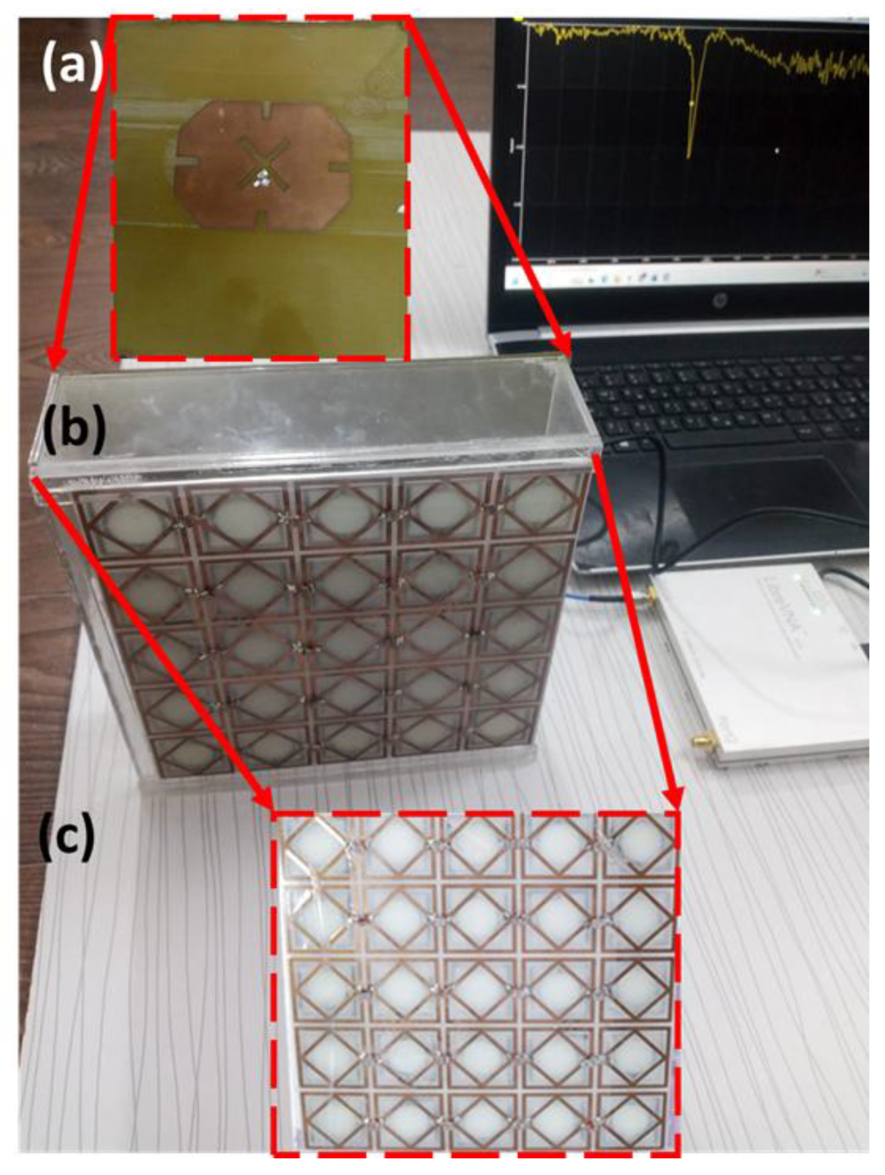
In this section, the proposed antenna is fabricated using the chemical wet etching process, as seen in Figure 9. As shown in Figure 9, the antenna prototype is fabricated using a standard photolithography method. The considered patch antenna part is shown in Figure 9a. The entire antenna system based on the proposed study is presented in Figure 9b. The proposed RIS is shown in Figure 9c. The proposed antenna is tested in terms of S11 and radiation patterns. The S11 results are measured using a LibreVNA 2-port full VNA 100 kHz–6 GHz Network Analyzer (VNA), Portman House, 2 Portman St, London W1H 6DU, UK. The radiation patterns are measured by a dual-polarized horn antenna (LB-SJ-20180), N9030A PXA signal analyzer, Portman House, 2 Portman St, London W1H 6DU, UK, and signal generator inside an RF chamber.

4.1. Antenna Performance Validation

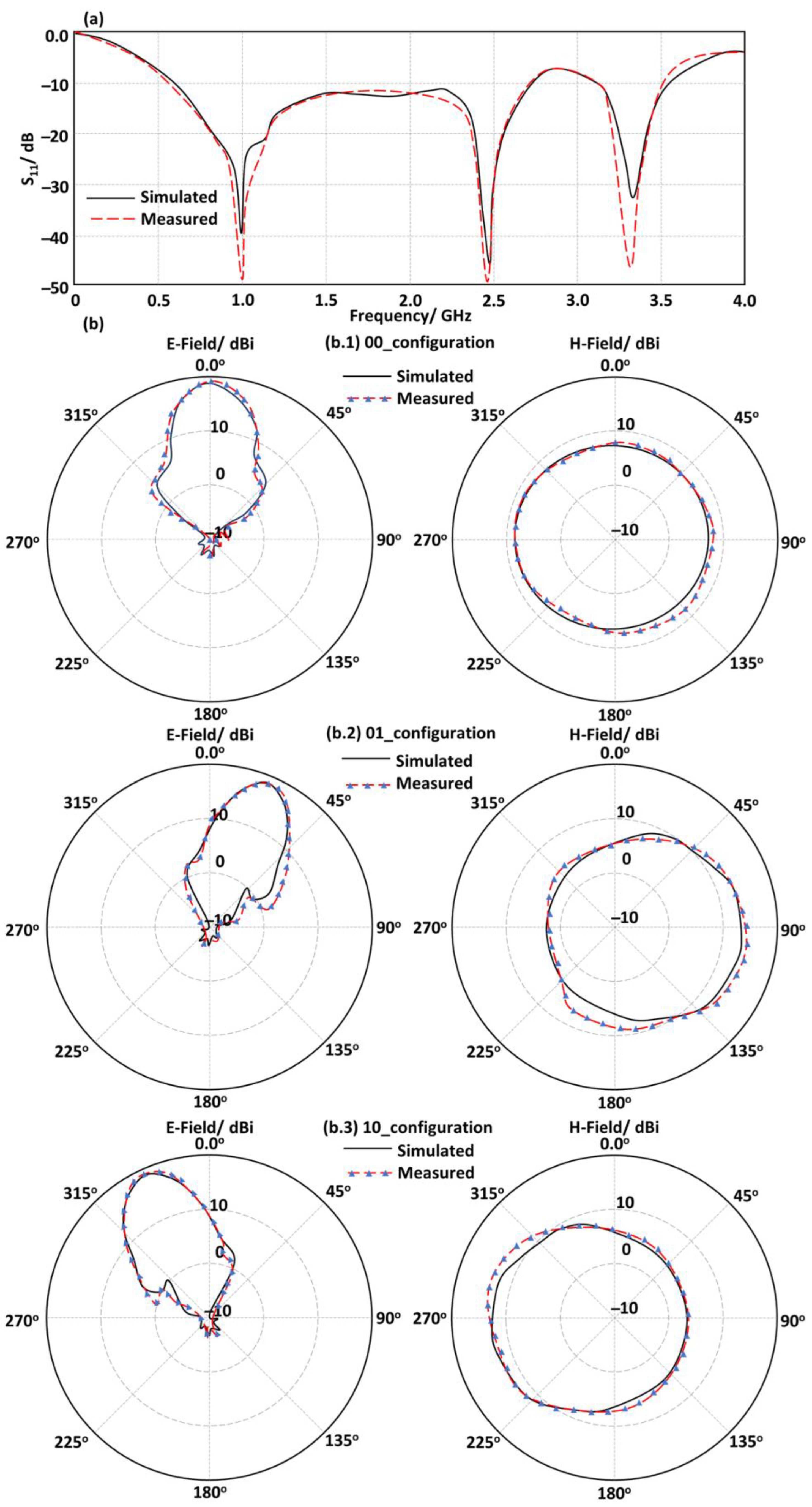
The numerical predictions from CST MWS show excellent agreement with experimental validation, indicating that the integrated antenna–RIS system achieves a broad impedance bandwidth from 0.9 GHz to 3.5 GHz, facilitating effective power transfer and low reflection, as shown in Figure 10. This is attributed to multiple resonances from RIS–antenna coupling that create a continuous operational band. Radiation pattern measurements reveal that the RIS layer modifies the aperture field to produce a highly directive main beam by enhancing constructive interference in the desired direction, significantly reducing side and back lobes. The RIS structure allows for frequency-dependent phase correction, maintaining effective wavefront collimation across a wide frequency range. Functioning similarly to a phase array antenna, it employs tunable reactive loads instead of active phase shifters. The close alignment of simulated and measured results confirms the accuracy of the design model, indicating potential applications in smart wireless communication systems requiring adaptive beam steering over a broad bandwidth. The measurements emphasize that the proposed antenna shows excellent beam steering from −22° to +22°; this is realized through switching LDR devices from 00 to 01 to 10 status.
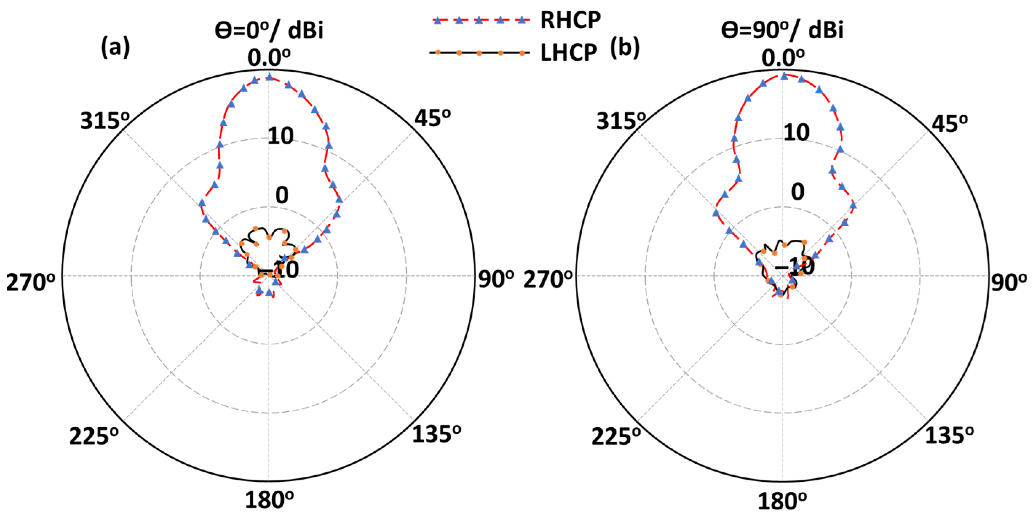
The proposed metasurface-loaded patch antenna exhibits strong circular polarization (CP) performance across the operating band, with a well-defined broadside main lobe and a 3 dB beamwidth of approximately 19° as seen in Figure 11. The cross-polar level remains at least 17 dB below the co-polar component over the main beam in both the E- and H-planes, corresponding to cross-polarization discrimination (XPD) exceeding the 15–20 dB benchmark generally accepted for high-quality CP antennas. This low cross-polarization level directly verifies the antenna’s ability to maintain a dominant right-hand or left-hand circularly polarized field. The proposed MTS plays a pivotal role in achieving this performance by acting as a high-impedance surface that provides an in-phase reflection that suppresses surface waves and enhances the vertical electric field above the ground plane. This boosts the broadside gain and equalizes the amplitudes of the TM10 and TM01 modes excited by the asymmetric patch geometry, resulting in cleaner circular polarization with minimal axial-ratio variation across the main lobe. Another indicator of robust CP behavior is the symmetry of the radiation pattern, with similar half-power beamwidths and negligible pattern distortion in both E- and H-plane cuts. This stability is particularly valuable in real-world deployments where the relative orientation between transmitting and receiving nodes may change. In summary, the measured co-/cross-polar patterns validate that the proposed MTS-loaded patch antenna achieves true circular polarization, meeting the stringent requirements for modern applications, delivering high radiation efficiency and polarization purity despite the absence of direct AR measurement.

4.2. Channel Performance

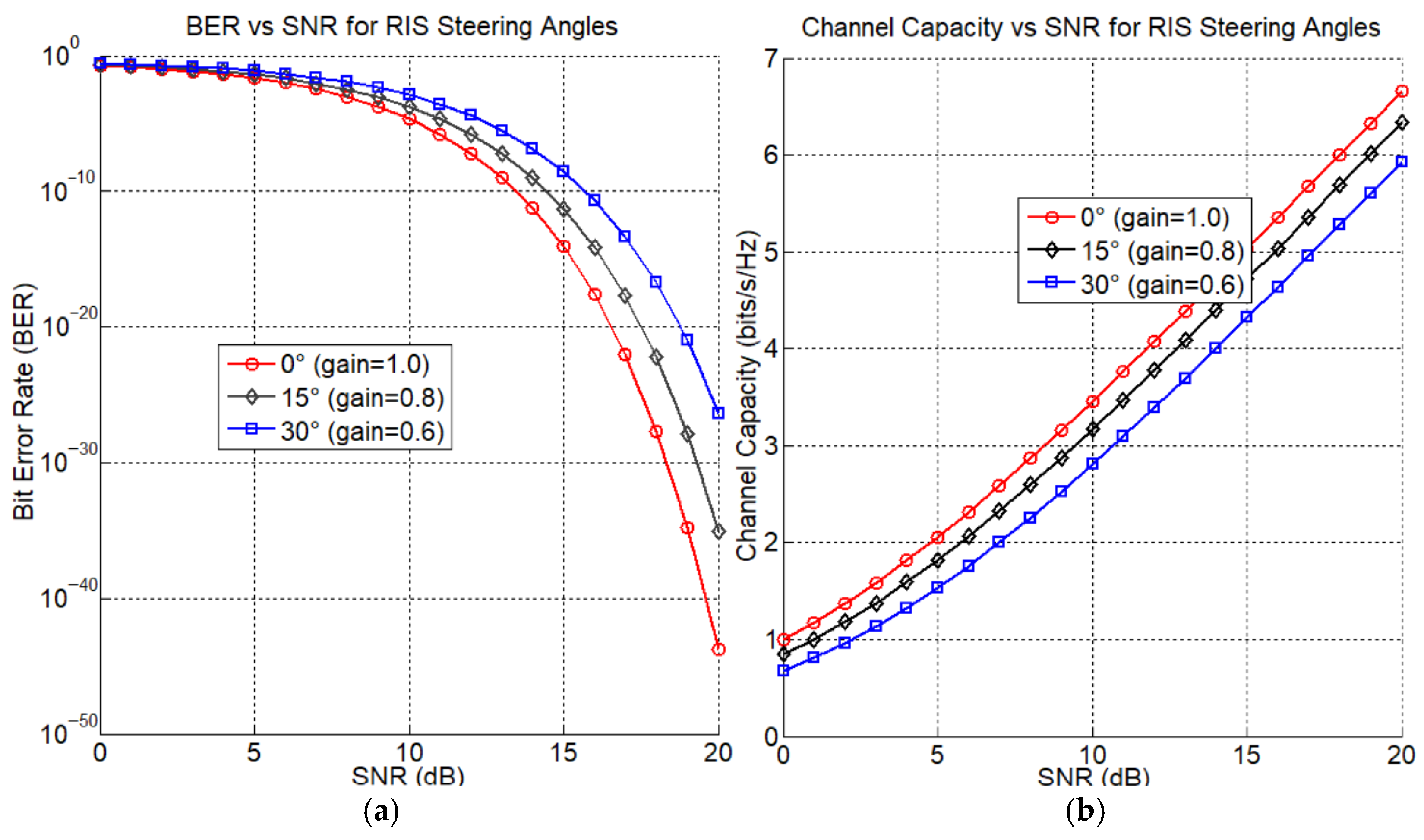
The proposed RIS utilizing LDR switches provides notable advancements in passive beam steering, achieving effective steering across ±22° at 5.8 GHz. While the system exhibits energy efficiency, the switching speed is relatively slow. Practical results indicate that optimal alignment at 0° improves performance, while a 15° misalignment slightly degrades BER and CC as shown in Figure 12. Table 1 compares this antenna design with previously introduced designs, highlighting its miniaturized structure and efficient radiation properties suitable for sub-6 GHz applications, with a gain range of 10.5 dBi to 16.8 dBi across 0.9–3.5 GHz. The use of LDR-based low-dropout resistor topologies enables quick reconfiguration and minimal insertion loss.

5. Conclusions

The study focuses on the construction, optimization, and validation of a RIS-assisted antenna system that operates across a frequency range of 0.9 GHz to 3.5 GHz. The antenna integrates a compact antenna with a RIS layer controlled by LDR switches, enhancing the antenna gain and allowing radiation pattern adjustment. The optimal performance is achieved with a 20 mm separation between the antenna and the RIS, emphasizing the importance of coupling optimization in RIS-assisted systems. The gain advantage is not limited to broadside operation, as the RIS maintains good aperture efficiency even at steering angles of ±22°. The beam steering feature works by carefully altering the LDR biasing settings of the RIS unit cells, allowing the device to steer the primary beam over a range of ±22° by carefully choosing the switching patterns. The experimental validation, employing VNA measurements for S11 and radiation pattern characterization in an RF chamber, corroborates simulation results from CST Microwave Studio with remarkable concordance. The proposed metasurface-assisted, circularly polarized antenna is designed for high gain (16.8 dBi), low cross-polarization, and compact beam steering at 0.915 GHz, making it suitable for various wireless applications. Future work plans include redesigning MTS geometry for a broader high-impedance response, integrating dual- or multi-band operation, enhancing beam steering, and miniaturizing and integrating compact IoT nodes and UAV platforms.

Author Contributions

Methodology, M.A.A.; Software, M.A.A.; Validation, M.A.A.; Investigation, O.N.U.; Writing—original draft, O.N.U. All authors have read and agreed to the published version of the manuscript.

Funding

This research was funded by International Applied and Theoretical Research Center (IATRC) with grant number [00A119].

Data Availability Statement

The original contributions presented in this study are included in the article. Further inquiries can be directed at the corresponding author.

Acknowledgments

The authors would like to express their thanks to Taha A. Elwi from the International Applied and Theoretical Research Center (IATRC) for his valuable support during the work of this research.

Conflicts of Interest

The authors declare no conflicts of interest.

References

  1. Wu, Q.; Zhang, R. Toward smart and reconfigurable environment: Intelligent reflecting surface aided wireless network. IEEE Commun. Mag. 2020, 58, 106–112. [Google Scholar] [CrossRef]
  2. Di Renzo, M.; Debbah, M.; Phan-Huy, D.-T.; Zappone, A.; Alouini, M.-S.; Yuen, C.; Sciancalepore, V.; Alexandropoulos, G.C.; Hoydis, J.; Gacanin, H.; et al. Smart radio environments empowered by reconfigurable AI meta-surfaces: An idea whose time has come. J. Wirel. Commun. Netw. 2019, 2019, 129. [Google Scholar] [CrossRef]
  3. Björnson, E.; Özdogan, Ö.; Larsson, E.G. Intelligent Reflecting Surface Versus Decode-and-Forward: How Large Surfaces are Needed to Beat Relaying? IEEE Wirel. Commun. Lett. 2020, 9, 244–248. [Google Scholar] [CrossRef]
  4. Tang, W.; Dai, J.Y.; Chen, M.; Li, X.; Cheng, Q.; Jin, S.; Wong, K.-K.; Cui, T.J. Programmable metasurface-based RF chain-free 8PSK wireless transmitter. Electron. Lett. 2019, 55, 417–420. [Google Scholar] [CrossRef]
  5. Huang, C.; Alexandropoulos, G.C.; Yuen, C.; Debbah, M. Indoor Signal Focusing with Deep Learning Designed Reconfigurable Intelligent Surfaces. In Proceedings of the 2019 IEEE 20th International Workshop on Signal Processing Advances in Wireless Communications (SPAWC), Cannes, France, 2–5 July 2019; pp. 1–5. [Google Scholar] [CrossRef]
  6. Gudla, V.V.; Kumaravelu, V.B.; Imoize, A.L.; Castillo Soria, F.R.; Sujatha, A.B.; John Kennedy, H.S.; Jadhav, H.K.; Murugadass, A.; Sur, S.N. Performance Analysis of Reconfigurable Intelligent Surface-Assisted Millimeter Wave Massive MIMO System Under 3GPP 5G Channels. Information 2025, 16, 396. [Google Scholar] [CrossRef]
  7. Ali, Q.; Shahzad, W.; Ahmad, I.; Safiq, S.; Bin, X.; Abbas, S.M.; Sun, H. Recent Developments and Challenges on Beam Steering Characteristics of Reconfigurable Transmitarray Antennas. Electronics 2022, 11, 587. [Google Scholar] [CrossRef]
  8. Worka, C.E.; Khan, F.A.; Ahmed, Q.Z.; Sureephong, P.; Alade, T. Reconfigurable Intelligent Surface (RIS)-Assisted Non-Terrestrial Network (NTN)-Based 6G Communications: A Contemporary Survey. Sensors 2024, 24, 6958. [Google Scholar] [CrossRef]
  9. Puspitasari, A.A.; Lee, B.M. A Survey on Reinforcement Learning for Reconfigurable Intelligent Surfaces in Wireless Communications. Sensors 2023, 23, 2554. [Google Scholar] [CrossRef]
  10. Yu, Y.; Wang, J.; Zhou, X.; Wang, C.; Bai, Z.; Ye, Z. Review on Channel Estimation for Reconfigurable Intelligent Surface Assisted Wireless Communication System. Mathematics 2023, 11, 3235. [Google Scholar] [CrossRef]
  11. Souto, V.D.P.; Souza, R.D.; Uchôa-Filho, B.F.; Li, Y. Intelligent Reflecting Surfaces Beamforming Optimization with Statistical Channel Knowledge. Sensors 2022, 22, 2390. [Google Scholar] [CrossRef]
  12. Chen, J.; Liang, Y.-C.; Pei, Y.; Guo, H. Intelligent Reflecting Surface: A Programmable Wireless Environment for Physical Layer Security. IEEE Access 2019, 7, 82599–82612. [Google Scholar] [CrossRef]
  13. Chen, X.; Ye, J.; Wei, Y.; Shi, J.; Zhu, J. Deep Learning-Based Joint Beamforming Design for Multi-Hop Reconfigurable Intelligent Surface (RIS)-Aided Communication Systems. Electronics 2024, 13, 3570. [Google Scholar] [CrossRef]
  14. Rapudu, T.C.; Oyerinde, O.O. Machine Learning-Based Channel Estimation for Multi-RIS-Assisted mmWave Massive-MIMO OFDM System in a Dynamic Environment. IEEE Trans. Wirel. Commun. 2025, 24, 5297–5309. [Google Scholar] [CrossRef]
  15. Tang, W.; Chen, M.Z.; Dai, J.Y.; Zeng, Y.; Zhao, X.; Jin, S.; Cheng, Q.; Cui, T.J. Wireless Communications with Programmable Metasurface: New Paradigms, Opportunities, and Challenges on Transceiver Design. IEEE Wirel. Commun. 2020, 27, 180–187. [Google Scholar] [CrossRef]
  16. You, X.; Wang, C.-X.; Huang, J.; Gao, X.; Zhang, Z.; Wang, M.; Huang, Y.; Zhang, C.; Jiang, Y.; Wang, J.; et al. Towards 6G wireless communication networks: Vision, enabling technologies, and new paradigm shifts. Sci. China Inf. Sci. 2021, 64, 110301. [Google Scholar] [CrossRef]
  17. Qian, B.; Qiao, J.; Zhang, C. STAR-RIS-Assisted Millimeter-Wave Secure Communication with Multiple Eavesdroppers. Mathematics 2024, 12, 2259. [Google Scholar] [CrossRef]
  18. Bashar, B.S.; Al-Sharify, T.A.; Rhazali, Z.A.; Misran, H.; Ismail, M.M.; Oleiwi, T.A. Miniaturized MTM Antenna for 5.7 GHz Services. In Proceedings of the 2024 4th International Conference on Artificial Intelligence and Signal Processing (AISP), Vijayawada, India, 26–28 October 2024; pp. 1–5. [Google Scholar] [CrossRef]
  19. Bashar, B.S.; Mejbel, B.G.; Rhazali, Z.A.; Misran, H.; Ismail, M.M.; Oleiwi, T.A. Design of Metasurface Antenna for 5G Applications. In Proceedings of the 2024 4th International Conference on Artificial Intelligence and Signal Processing (AISP), Vijayawada, India, 26–28 October 2024; pp. 1–4. [Google Scholar] [CrossRef]
  20. Al Naiemy, Y.; Abdulateef, A.N.; Hamad, A.R.; Ismael, M.S.; Ruthramurthy, B.; Elwi, T.A.; Nagy, L.; Zwick, T. A Further Realization of Binary Genetic Algorithm to Design a Dual Frequency Band Rectenna for Energy Harvesting in 5G Networks. Diyala J. Eng. Sci. 2025, 18, 203–214. [Google Scholar] [CrossRef]
  21. Kamil, R.A.; Alsabti, S.M.B.; Abdulsattar, R.K.; Mohammed, A.H.; Elwi, T.A. On the Enhancement Anomaly Detection for RF Bio-Sensors by Computing Artificial Networks Using Machine Learning Techniques. Infocommun. J. 2025, XVII, 89–95. [Google Scholar] [CrossRef]
  22. Verho, S.; Nguyen, V.T.; Chung, J.-Y. A 4 × 4 Active Antenna Array with Adjustable Beam Steering. Sensors 2023, 23, 1324. [Google Scholar] [CrossRef]
  23. Nabeel, M.I.; Singh, K.; Afzal, M.U.; Thalakotuna, D.N.; Esselle, K.P. Dual-Band Passive Beam Steering Antenna Technologies for Satellite Communication and Modern Wireless Systems: A Review. Sensors 2024, 24, 6144. [Google Scholar] [CrossRef]
  24. Dmitriev, V.; de Oliveira, R.M.S.; Paiva, R.R.; Rodrigues, N.R.N.M. Multifunctional THz Graphene Antenna with 360° Continuous ϕ-Steering and θ-Control of Beam. Sensors 2023, 23, 6900. [Google Scholar] [CrossRef] [PubMed]
  25. Verho, S.; Chung, J.-Y. Design of a Compact and Minimalistic Intermediate Phase Shifting Feed Network for Ka-Band Electrical Beam Steering. Sensors 2024, 24, 1235. [Google Scholar] [CrossRef]
  26. Ma, S.; Li, X.-N.; Li, Z.-D.; Ding, J.-J. Electronic Beam Steering Metamaterial Antenna with Dual-Tuned Mode of Liquid Crystal Material. Sensors 2023, 23, 2556. [Google Scholar] [CrossRef] [PubMed]
  27. Taher, F.; Rasheed, W.S.; Elwi, T.A.; Al-Khaylani, H.H.; Sree, M.F.A.; Fatah, S.Y.A.; Abdel-aleim, M.M.; El-Din, M.S.H.S. Novel Reconfigurable Fractal Antenna Design for Modern Communication Systems. J. Adv. Res. Appl. Sci. Eng. Technol. 2025, 64, 47–57. [Google Scholar] [CrossRef]
  28. Ali, M.M.; Segura, E.M.; Elwi, T.A. Advancements in Ku Band Resonator Composite Right/Left-Handed (CRLH) MTMs: Design, Analysis, and Applications. J. Eng. Sustain. Dev. 2025, 29, 184–189. [Google Scholar] [CrossRef]
  29. Abdulkareem, Z.J.; Hamad, T.K.; Elwi, T.A. Reconfigurable metasurface based on graphene optical antennas for dynamic beam steering. Sustain. Eng. Innov. 2025, 7, 127–136. [Google Scholar] [CrossRef]
  30. Dai, L.; Wang, B.; Wang, M.; Yang, X.; Tan, J.; Bi, S.; Xu, S.; Yang, F.; Chen, Z.; Di Renzo, M.; et al. Reconfigurable Intelligent Surface-Based Wireless Communications: Antenna Design, Prototyping, and Experimental Results. IEEE Access 2020, 8, 45913–45923. [Google Scholar] [CrossRef]
  31. Alaukally, M.N.N.; Ilyas, M.; Oleiwi, T.A. On the performance revision of a wearable antenna sensor for glucose detection utilizing artificial neural networks. Power Syst. Technol. 2025, 49, 1121–1155. [Google Scholar] [CrossRef]
  32. Tong, X.; Chen, Y.; Deng, Z.; Hu, E. An Off-Grid DOA Estimation Method via Fast Variational Sparse Bayesian Learning. Electronics 2025, 14, 2781. [Google Scholar] [CrossRef]
  33. Burchfield, S.; Givhan, C.; Martin, S. A Beam Steering Vector Tracking GNSS Software-Defined Receiver for Robust Positioning. Sensors 2025, 25, 1951. [Google Scholar] [CrossRef]
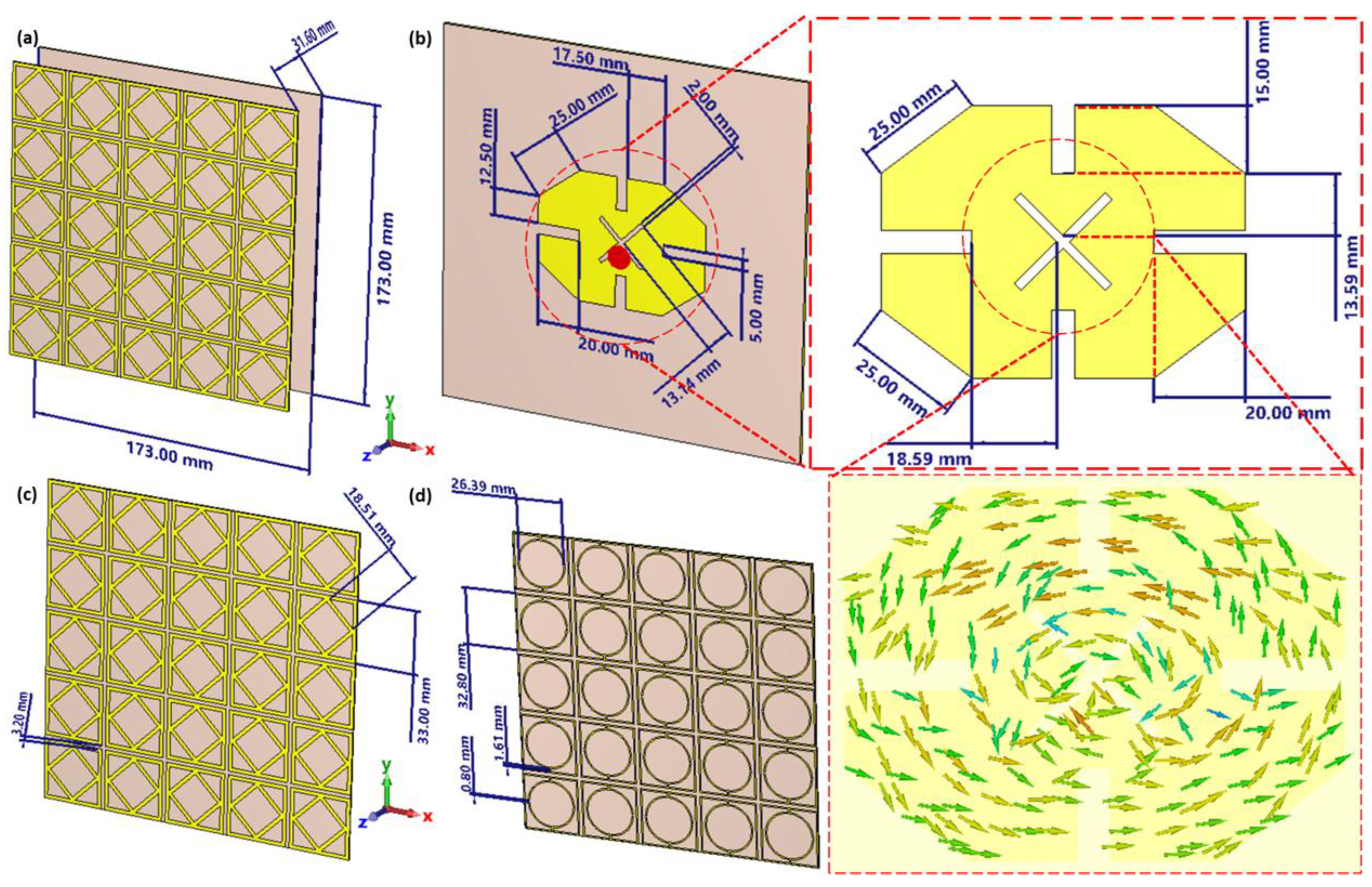
Figure 1. Configuration of the proposed antenna: (a) 3D view, (b) antenna patch view, (c) RIS front view, and (d) RIS back view.
Electronics 14 04039 g001
Figure 2. The considered cases.
Electronics 14 04039 g002
Figure 3. Simulated results of the antenna without RIS layer: (a) S11 spectra, (b) polarization spectra, and (c) gain spectra.
Electronics 14 04039 g003
Figure 4. The proposed unit cell of the proposed RIS: (a) unit cell details and (b) waveguide analysis.
Electronics 14 04039 g004
Figure 5. The evaluated S-parameters of the proposed RIS unit cell: (a) evaluated S11 and (b) S12.
Electronics 14 04039 g005
Figure 6. The evaluated S-parameters of the proposed RIS unit cell with different switching configurations: (a) evaluated S11 and (b) S12.
Electronics 14 04039 g006
Figure 7. Simulated results of the antenna with RIS layer: (a) S11 spectra, (b) polarization spectra, and (c) gain spectra.
Electronics 14 04039 g007
Figure 8. The evaluated antenna radiation patterns based on the RIS layer with different configuration processes: (a) E-Plane and (b) H-Plane.
Electronics 14 04039 g008
Figure 9. The fabricated antenna prototype: (a) the considered antenna patch, (b) the antenna structure, and (c) the proposed RIS.
Electronics 14 04039 g009
Figure 10. Antenna validation results: (a) S11 spectrum and (b) radiation patterns at 0.915 GHz across different switching configurations. (b.1) Antenna radiation patterns in the 00_configuration, (b.2) antenna radiation patterns in the 01_configuration, and (b.3) antenna radiation patterns in the 10_configuration.
Electronics 14 04039 g010
Figure 11. Measured antenna radiation patterns at 0.915 GHz with different polarizations and orientations: (a) E-Plane and (b) H-Plane.
Electronics 14 04039 g011
Figure 12. The evaluated performance in terms of (a) BER and (b) CC.
Electronics 14 04039 g012
Table 1. A comparison between the proposed study and other published results.
Size/mm2Bandwidth (BW)GainBeam Steering AngleCC ImpactSwitching TechniqueRef.
173 × 1730.9–3.5 GHz (~2.6 GHz span)10.5–16.8 dBi±22°Capacity: ~5.4 bits/s/Hz at 0° steering (16.8 dBi), ~4.8 bits/s/Hz at ±22° (10.5 dBi); BER < 10−5 at SNR > 15 dBLDRThis Work
800 × 800350 MHz (−1 dB BW)23 dBi at 2.3 GHz; 19.1 dBi at 28.5 GHz0–60° (broadside) steeringNot explicitly stated2-bit phase shifting with PIN diodes[29]
300 × 30022.5–29.5 GHz (26.9% fractional BW)(Not specified indBi)±50°Not quantitatedOne-bit PIN switches[30]
400 × 400Dual-band(Not specified)±35° (sub-6), ±30° (mmWave)Not quantitatedRF switches controlling shared aperture[31]
210 × 140~4% BW at 5 GHz~8 dBi±40° elevation and multi-azimuth+29% coverage capacity, +16% throughputPIN diode-controlled pixels[32]
140 × 200Dual-frequency(Not stated)10–45° at 27 GHz and 31 GHz+50% at 20 dB SNR; +84% at 60 dBVaractor tuning via ML biasing[33]
Disclaimer/Publisher’s Note: The statements, opinions and data contained in all publications are solely those of the individual author(s) and contributor(s) and not of MDPI and/or the editor(s). MDPI and/or the editor(s) disclaim responsibility for any injury to people or property resulting from any ideas, methods, instructions or products referred to in the content.