Abstract
This paper presents a control delay compensation method for an LLCL-type active power filter (APF), aimed at improving performance in digital control systems. The proposed strategy is directly integrated into the inner-loop current controller, requiring no additional compensation modules, predictor structures, or capacitor current feedback, which simplifies the control structure and increases flexibility. The method uses real-time internal state responses of the controller to actively compensate for the phase lag caused by digital control delay, effectively maintaining current control accuracy and overall system dynamic stability. Simulation studies based on a 5.5 kW APF system are conducted to verify the effectiveness of the approach. The results show improved current tracking accuracy, stable dynamic behavior under various load conditions. The simulation-based results indicate the potential of the proposed method for improving control accuracy and stability in digitally controlled APF systems. Moreover, very few studies have addressed control delay compensation specifically for LLCL-based APF systems, making this work a valuable contribution to the field.
1. Introduction
With the increasing use of nonlinear loads—such as computers, inverters, and various electronic devices—power quality issues in modern power systems have become more critical. These loads cause voltage and current waveform distortions, leading to harmonic pollution and excessive reactive power, which reduce system stability and efficiency. Harmonics can result in equipment overheating, mechanical vibrations, and premature aging, while reactive power increases energy losses in transmission lines and transformers, raising operational costs and causing unnecessary energy waste. Such problems not only affect the performance of the power grid but also pose risks to sensitive devices and overall system reliability. Therefore, mitigating power quality problems caused by nonlinear loads has emerged as an important and ongoing research focus in the field of power engineering [1]. To address the aforementioned challenges, researchers have proposed a variety of strategies aimed at improving power quality, among which APFs have attracted considerable attention due to their superior compensation capabilities and real-time dynamic response performance [2,3]. APFs are capable of actively injecting compensating currents to eliminate harmonic components while simultaneously providing reactive power compensation, thereby stabilizing voltage and current waveforms within the power grid. Compared with conventional passive filters, APFs offer enhanced adaptability and precise control, allowing them to promptly adjust in response to varying load conditions and maintain efficient operation under complex and dynamic grid environments. Current research on APF primarily focuses on the design of control strategies and the optimization of system architectures. High-performance and fast control algorithms can significantly improve the response speed and compensation accuracy of the filters, enabling them to react in real time to load fluctuations. Meanwhile, optimizing the hardware architecture of the filters contributes to overall system stability and enhances energy utilization efficiency. Furthermore, by improving the reactive power compensation capability, APF can effectively reduce energy losses within the system, thus achieving higher energy efficiency. With the rapid development and large-scale integration of renewable energy technologies, such as solar and wind power, power systems are increasingly exposed to uncertainties and power quality challenges, including intermittent generation and frequent voltage fluctuations. These conditions further emphasize the necessity for advanced APF solutions capable of maintaining grid stability and ensuring high-quality power delivery under increasingly variable operating conditions. APFs have been extensively studied as effective solutions for improving power quality, due to their ability to actively compensate harmonic currents and reactive power in real time. Among the various APF configurations, the Shunt Active Power Filter (SAPF) [4,5,6] has emerged as one of the most widely adopted implementations. Unlike general APF, SAPF are connected in parallel with the power system, making them particularly suitable for mitigating current harmonics and providing reactive power compensation in dynamic and nonlinear load conditions. This specific configuration enables SAPF to respond instantaneously to load variations and maintain high compensation accuracy, which is especially important in power systems with a high penetration of renewable energy sources. Consequently, integrating SAPF into modern power networks not only enhances system stability and reliability but also facilitates the efficient utilization of renewable energy, contributing to the development of cleaner, smarter, and more sustainable power grids.
In the control of APFs, the increasing complexity of control algorithms, combined with the delays introduced by the sampling-and-hold process and pulse-width modulation (PWM), often drives the overall system closer to instability due to phase lag, and in severe cases may even result in divergence. To address this critical issue, numerous delay compensation strategies have been successively proposed in the literature, aiming to mitigate the adverse impact of control delays on system stability and dynamic performance. These compensation techniques not only help maintain robust operation under high switching frequencies and rapidly changing load conditions but also improve the accuracy of harmonic mitigation and reactive power compensation, thereby ensuring the reliable functioning of APF systems in modern power networks. First, Xin et al. [7] proposed a grid current feedback control strategy that integrates a Second-Order Generalized Integrator (SOGI) in order to enhance the stability of grid-connected systems employing LCL filters. In this method, the SOGI structure is utilized to compensate for digital control delays, thereby improving both the immediacy and robustness of current feedback. However, the control performance of this approach strongly depends on the accurate setting of the grid fundamental frequency; any deviation in frequency, or the absence of integration with a phase-locked loop (PLL), will significantly degrade the compensation effect. Moreover, since the SOGI framework incorporates dual integrators and multipliers, it imposes a relatively high computational burden on DSP hardware resources. Practical implementations must also carefully consider issues such as integrator drift, noise interference, and numerical stability, all of which may affect overall system reliability. Ding et al. [8] addressed the challenges of weak grid conditions by proposing a delay compensation strategy that combines a Proportional Complex-Integral (PCI) controller with a second-order low-pass filter. The primary objective of this method is to extend the compensation frequency range, thereby enhancing the robustness of system control under fluctuating grid parameters. Although the PCI controller exhibits excellent delay compensation capability, its design process requires highly precise tuning of complex parameters and relies heavily on the accuracy of the system’s dynamic model. Furthermore, the implementation of this approach involves complex-valued computations and increased hardware resource consumption, which may limit its applicability and flexibility in embedded systems or platforms with constrained computational resources. Another study [9] proposed a delay compensation approach within the Finite Control Set Model Predictive Control (FCS-MPC) framework by incorporating a time-prediction mechanism to offset one control period of digital delay. This strategy can significantly enhance prediction accuracy and improve control response speed. However, its implementation requires high-order differential models and Lagrange extrapolation algorithms, which considerably increase the overall computational complexity. In addition, the method is highly coupled with the switching vector optimization algorithm, posing challenges both to the computational capacity of the controller and to the stability of the system. Lin et al. [10] proposed a dual-sampling real-time computation method that effectively mitigates the impact of digital control delays on the performance of LCL-filter-based grid-connected inverters, demonstrating strong delay compensation capability. However, several practical challenges may arise in applications. First, the dual-sampling mechanism substantially increases the computational burden on the digital controller and imposes stricter requirements on timing synchronization and interrupt handling, particularly under high switching frequency conditions. Furthermore, this method necessitates two current measurements within a single control period; if the associated measurement filters or hardware design are not adequately optimized, noise interference may be exacerbated, potentially compromising the stability and reliability of the control system.
To overcome these limitations, this study proposes a control delay compensation method embedded directly within the inner-loop current controller. The mechanism is fully integrated into the controller architecture, eliminating the need for separate compensating modules or predictive structures, and without relying on additional feedback signals such as capacitor currents. This integration improves system compactness. By actively counteracting phase and gain errors induced by digital control delays through real-time controller state response, the method effectively maintains current control accuracy and overall dynamic stability. Simulation results validate that the proposed approach not only provides effective compensation but also ensures stable operation and precise control, demonstrating strong potential for practical applications, particularly in the LLCL-type APF system developed in this work. The comparison table of previous works and the proposed method is shown in Table 1. The following section systematically presents the proposed control delay compensation method. First, the theoretical foundation and design architecture are introduced, providing a detailed explanation of the control principle and highlighting how the method effectively overcomes common delays in digital control systems while enhancing overall control accuracy. To the best of our knowledge, studies on control delay compensation strategies in LLCL-type APF systems are still lacking, and this work seeks to provide an initial contribution to address this gap. Subsequently, system stability is evaluated through mathematical modeling and frequency-domain analysis, investigating the influence of the compensation strategy on system stability to ensure robust and reliable performance under various operating conditions. Finally, the proposed method is validated through comprehensive simulations conducted in Matlab/Simulink on a 5.5 kW system under multiple scenarios and load-switching conditions, including transient responses and abrupt load changes. These results demonstrate the compensation effectiveness and dynamic performance of the method. In particular, the main contributions are listed as follows:

Table 1.
Comparison table.
- The proposed control achieves effective delay compensation without requiring additional sensors or predictive controllers.
- Only the inner-loop compensation is used, resulting in lower cost and higher fault tolerance.
- For LLCL-type APFs, this work provides a novel perspective that fills a research gap in the existing literature.
2. Materials and Methods
2.1. Architecture of LLCL-Type Active Power Filter
As shown in Figure 1, the system architecture mainly consists of two primary components: (1) a rectifier and (2) an APF. The system input voltage Vg serves as the main power source for the entire system. The rectifier is responsible for converting the AC voltage into DC voltage to supply the DC load Ro. However, the nonlinear characteristics of the rectification process introduce significant harmonic distortion, causing the current waveform to deviate considerably from the ideal sinusoidal shape. This not only degrades power quality but also results in a substantial increase in the total harmonic distortion (THD) of the current. To effectively suppress the harmonic pollution generated by the rectifier and to significantly improve the current THD of the overall system, an APF is integrated into the power network. This APF is implemented using an LLCL-type full-bridge topology. The APF is capable of real-time monitoring of the grid current signals, and through the use of high-precision current sensors, it accurately extracts the non-ideal components embedded in the load current iL with particular emphasis on the low-order harmonic components. The system is capable of identifying the frequency and phase information of the target harmonics. Based on this analysis, the APF actively generates a set of compensating currents ig that possess the same frequency but an opposite phase to the harmonics to be mitigated. These compensation currents are then injected into the grid in real time, ensuring an effective cancelation of the undesired harmonic components. As a result of this compensation mechanism, the grid-side current ia can closely approximate an ideal sinusoidal waveform, thereby improving current quality and significantly reducing the THD. Through this approach, the system not only suppresses current distortion induced by rectifiers and other nonlinear loads, but also alleviates equipment interference and thermal losses caused by harmonics, ultimately enhancing grid operational stability and improving overall energy utilization efficiency.
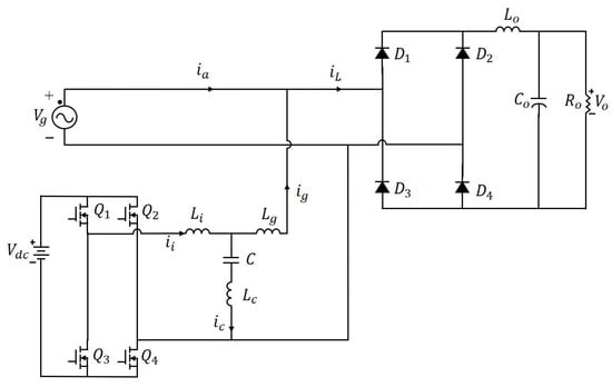
Figure 1.
LLCL-type APF system architecture, illustrating the main components.
To enhance the suppression capability of the APF against high-order harmonics, this study specifically addresses the harmonics generated during the inverter switching process (Q1~Q4), with particular attention to the high-frequency harmonics occurring around the switching frequency of 20 kHz. To achieve this objective, the output stage of the APF inverter adopts an LLCL filter topology. Compared with the conventional LCL filter, the LLCL configuration introduces an additional small series inductor Lc in the capacitor branch of the LCL structure, thereby improving the high-frequency attenuation characteristics and enabling effective suppression of specific higher-order harmonics. The presence of this additional inductor significantly increases the impedance around the switching frequency, reinforcing the attenuation of high-frequency switching harmonics. Consequently, the THD in the output current is effectively reduced, resulting in improved grid current quality. Furthermore, the LLCL filter demonstrates a steeper frequency attenuation slope compared to traditional LC and LCL structures. This property allows the use of smaller inductance Lc and capacitance C values for the passive components while still maintaining excellent high-order harmonic suppression. Such advantages not only reduce the physical size of the filter components but also contribute to a more compact circuit layout and higher overall system efficiency. Under the same filtering requirements, the LLCL topology achieves superior high-frequency harmonic suppression with smaller passive elements, offering improved power density and space utilization. Considering both filtering performance and overall system design requirements, the LLCL filter exhibits superior characteristics compared to LC or LCL filters, and is therefore adopted as the filtering topology in this study.
As shown in Figure 2, the control block diagram of the APF in this study can be divided into three main sections: the LLCL filter transfer function GLLCL(s), the controller transfer function Gc(s), and the conversion from the inverter switching duty cycle d to the output voltage vt. First, the LLCL filter transfer function GLLCL(s) is established based on the equivalent linear circuit, which includes the inverter-side inductor Li, grid-side inductor Lg, filter capacitor C, and series inductor Lc. This transfer function reflects the current–voltage dynamic characteristics of the filter system in the frequency domain and is expressed as follows:

Figure 2.
APF control block diagram, without considering control delay, showing the main control loops of the system.
This transfer function describes the dynamic response from the inverter-side current ii to the inverter output voltage vt, serving as a fundamental basis for both controller design and stability analysis. Subsequently, the design of the controller Gc(s) focuses on enhancing the stability and responsiveness of the current-feedback loop, ensuring that the output current can accurately track the reference compensation current. The controller is implemented based on a proportional–integral structure, expressed as follows:
Next, the inverter modulation mechanism generates the corresponding output voltage vt through the control of the duty cycle d. Since a bipolar PWM switching scheme is employed in this system, the relationship between d and vt can be expressed as follows:
By integrating the three aforementioned blocks, the APF control block diagram illustrates the complete control process: the reference current input ii,ref and the feedback current ii are first subtracted, and the resulting error is processed by the controller to generate the reference modulation signal vt*. This signal is subsequently applied to the inverter, which, together with the LLCL filter, produces the desired compensating current ig. This comprehensive control framework not only defines the operational flow of the system but also provides a solid foundation for the design and stability analysis of the control delay compensation method proposed in the subsequent sections. In this study, the duty cycle d is derived from Equation (3), where the inverter output voltage vt is replaced with the reference modulation signal vt* to implement the closed-loop control strategy. The duty cycle d is expressed as follows:
To mitigate unexpected voltage harmonic disturbances on the grid side and to enhance overall compensation performance and control stability, a feedforward compensation mechanism based on the capacitor voltage vc is incorporated into the duty cycle d control strategy. This approach actively counteracts the impact of grid-side disturbances on the output voltage control. Consequently, Equation (4) is revised as follows:
In Equation (5), vt* represents the ideal inverter output voltage command, which can be further expressed as the product of the current control error and the controller transfer function Gc(s)(ii,ref − ii), where ii,ref denotes the desired reference compensation current, and ii is the actual feedback current measured on the inverter side. This relationship indicates that the controller generates the corresponding inverter voltage command vt* based on the real-time current error, driving the inverter to produce an accurate compensating current and thereby achieving effective harmonic suppression. Accordingly, Equation (5) can be expanded as follows:
In the following subsection, the duty cycle d expression derived in this subsection serves as the basis for further introducing a control delay compensation mechanism, aiming to enhance system stability and dynamic response performance under a digital control environment. To clearly illustrate the design of the compensation strategy, the control block diagram will be redrawn to incorporate the transfer function representing the control delay, thereby providing a more comprehensive depiction of the delay effects on the system’s dynamic behavior. Subsequently, based on the updated control block diagram, the control delay compensation mechanism will be applied to counteract the adverse impacts of control delay on the system.
2.2. Control Delay Compensation Mechanism
In this subsection, based on the control block diagram presented in the previous chapter, two updated control block diagrams will be illustrated. The first diagram incorporates the digital control delay transfer function, explicitly reflecting the significant impact of control delay on phase and gain margins. The second diagram further includes the control delay compensator, enabling a comparison of the system structure before and after compensation and highlighting the role of the compensator within the overall control loop. Through this comparison, the effectiveness of the control delay compensation mechanism in enhancing control accuracy and system stability can be systematically demonstrated. Figure 3 illustrates the control block diagram incorporating the effects of control delay. In this diagram, the delay transfer function is positioned after the duty cycle d to explicitly reflect the delay introduced by sampling and PWM in digital control systems on the dynamic response. The inherent digital control delay can be approximated as 1.5 control periods, including one sampling-period computation delay and an additional half sampling-period delay introduced by the PWM process. The proposed delay compensator effectively compensates delays up to 1.5 control periods, corresponding to the switching period of the system. Within this range, the compensator successfully mitigates the phase lag introduced by control delays, ensuring that the closed-loop system maintains stability and accurate current tracking under all considered operating conditions. Beyond 1.5 control periods, the compensation gradually becomes less effective, and the phase margin decreases, defining the practical operational limit of the compensator. The control delay function Gd(s) is expressed as follows:

Figure 3.
APF control block diagram, considering control delay (without delay compensation).
To further analyze the specific impact of control delay on system stability, the control block diagram shown in Figure 3 is equivalently simplified and transformed into the frequency-domain analysis model depicted in Figure 4. In this model, GPWM(s) is equivalently represented as follows:

Figure 4.
Simplified control block diagram incorporating control delay.
Based on the system transfer function corresponding to Figure 4, the complete open-loop transfer function GOL(s) can be derived, as expressed in Equation (9):
To explicitly represent the effects of control delay in the frequency domain, a second-order `Pade approximation is applied to the control delay transfer function, enabling its conversion into a rational function form, as shown in Equation (10):
Subsequently, based on Equation (9), the open-loop transfer function Bode plot is depicted in Figure 5. It can be observed that the system’s phase margin (PM) exhibits negative values (−70.6°), indicating that the current control architecture, without any compensation, operates within an unstable region. This instability could lead to control system divergence or even complete loss of stability. Therefore, it is essential to introduce a control delay compensation mechanism to enhance the overall system stability.
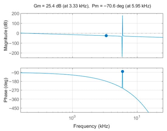
Figure 5.
Bode plot showing the open-loop characteristics without control delay compensation.
To address the issue of negative PM observed in the Bode plot, Figure 6 illustrates the control block diagram incorporating the proposed delay compensation mechanism. This mechanism introduces a negative feedback path at the controller output, where the feedback signal is scaled by a fixed gain Gcomp(s) before being subtracted from the original error signal at the controller input. Such a structure effectively adjusts the system’s phase characteristics and gain response, thereby enhancing the overall stability. Based on this compensation framework, the control block diagram can be further simplified, as shown in Figure 7, from which the modified open-loop transfer function is derived, as expressed in Equation (11).

Figure 6.
APF control block diagram with the proposed delay compensation mechanism.

Figure 7.
Simplified control block diagram with the proposed delay compensation mechanism.
Subsequently, based on Equation (11), the open-loop transfer function incorporating the delay compensation mechanism is plotted in the Bode diagram, as shown in Figure 8a. The pole-zero location diagram is shown in Figure 8b. The results clearly indicate that, with the introduction of the proposed compensation strategy, the system PM is significantly improved to a positive range (57.4°). This improvement effectively eliminates the instability risk associated with negative phase margins, thereby ensuring the stable operation of the overall control system. Moreover, Figure 8b exhibits seven poles and six zeros. After appropriate controller design, nearly all poles are stably located in the left-half plane. Although some zeros are positioned in the right-half plane, they do not affect the closed-loop stability. It is worth highlighting the contrast between Figure 5 and Figure 8a. As shown in Figure 5, the system without delay compensation exhibits a negative phase margin, indicating an inherently unstable operating condition. This instability arises from the phase lag introduced by digital control delays, which severely degrades the dynamic performance. In contrast, Figure 8a demonstrates that, after applying the proposed compensation mechanism, the phase margin shifts to a positive region with sufficient stability margin. This clear improvement verifies the effectiveness of the compensation strategy in counteracting delay-induced distortions and ensuring robust current control performance in the APF system.
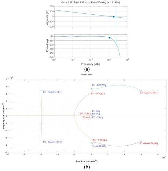
Figure 8.
Stability analysis diagram of the system with the proposed delay compensation mechanism: (a) bode plot; (b) pole-zero locations diagram.
2.3. Multiple Resonance and Stability Issues in LLCL-Type System
In this subsection, the multiple resonance and stability issues in the LLCL-type system is discussed. The transfer function of the LLCL-type system is derived in Equation (12).
From Equation (12), two resonance points can be identified, as expressed in Equations (13) and (14), which are shown below
Because the parameters Lc and C primarily determine the high-frequency resonant point responsible for harmonic attenuation (20 kHz), as shown in Equation (14), they are not modified to preserve the designed high-frequency filtering performance. Therefore, the parameter variation analysis focuses on Li and Lg, which dominate the low-frequency resonant point as indicated in Equation (13). The Bode plots in Figure 9 show that under nominal conditions and parameter deviations of −20%, −10%, and +10%, the system maintains stable phase margins. However, when Li and Lg increase by +20%, the phase margin drops to −58.1°, indicating instability. This occurs because the phase at the second 0 dB gain crossover falls below −180°, resulting in a loss of stability. These results demonstrate that the proposed system remains stable within a reasonable parameter variation range and confirm that the inner-loop control strategy can maintain stability without requiring capacitor current feedback or virtual damping. Nevertheless, the analysis also reveals a certain sensitivity to parameter deviations, suggesting that accurate component design is essential to ensure robust operation.
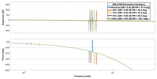
Figure 9.
Bode plots showing gain and phase margins under nominal and varied Li and Lg (±10%, ±20%) conditions.
3. Results and Discussion
In this study, the feasibility and performance of the proposed APF system with a control delay compensation mechanism are verified through system-level simulations using Matlab/Simulink R2024b. A complete system model is constructed on the Simulink platform, integrating the rectifier, APF main circuit, controller, and control delay compensation mechanism, in order to emulate the operation behavior under realistic power conditions. Subsequently, simulation tests70 are carried out to evaluate the system performance in terms of stability, dynamic response characteristics, and harmonic suppression capability under various operating scenarios. Finally, by comparing the voltage and current waveforms as well as the THD variations before and after introducing the compensation mechanism, the effectiveness of the proposed strategy in improving system stability and control performance is systematically discussed. The parameters of the simulated circuit are summarized in Table 2.

Table 2.
Main parameters of the simulated circuit.
Subsequently, system-level simulations are conducted to verify the overall performance and stability under different operating conditions. Four simulation scenarios are considered, as shown in Table 3.

Table 3.
Simulation scenarios.
3.1. Scenario 1-Rectifier Only (No APF)
Figure 10 illustrates the simulation waveforms of the original power system without the integration of the APF. As shown, the grid voltage Vg maintains a stable and symmetric sinusoidal waveform, with a peak value of approximately ±155 V, corresponding to an RMS value of about 110 V, which complies with the system design specifications. However, since no harmonic compensation mechanism is implemented, the grid current ia is entirely identical to the load current iL. Its waveform is significantly affected by the nonlinear rectifier-type load, resulting in pronounced peak distortions and low-order harmonic components. Compared with the ideal pure sinusoidal reference, clear deviations are observed, indicating that the system suffers from considerable current THD problems under the condition without filtering.
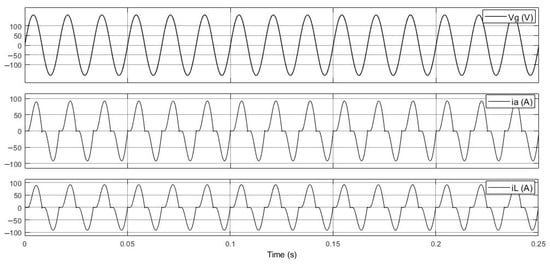
Figure 10.
Grid voltage and current waveforms of the original power system without APF, showing severe grid current distortion.
Figure 11 presents the frequency-domain analysis of the grid current using the fast Fourier transform (FFT) tool. The results indicate that the fundamental component (60 Hz) reaches a maximum value of 76.71 A, while the THD is as high as 25.84%. This clearly demonstrates that the grid current contains a substantial amount of low-order harmonic components, causing the waveform to deviate severely from the ideal sinusoidal shape. Such a distorted current not only elevates the overall THD of the power grid but may also pose operational instability risks to other electrical equipment. To address this issue, subsequent simulations introduce the APF for real-time compensation control in order to verify its effectiveness in improving grid current quality and suppressing harmonic disturbances.
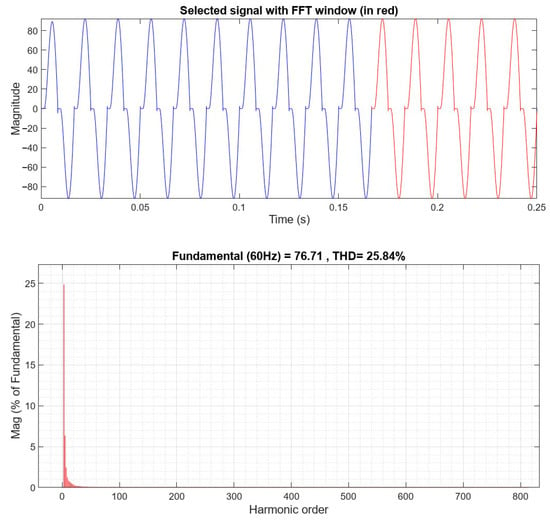
Figure 11.
Frequency-domain spectrum of the grid current without APF, highlighting significant harmonic distortion.
3.2. Scenario 2-APF Without Digital Control Delay
Figure 12 illustrates the voltage and current waveform responses of the overall power system after the introduction of the APF. In the present system configuration, the load current iL generated by the nonlinear load contains a significant amount of low-order harmonics, which, if directly supplied by the grid without compensation, would reduce the power factor and adversely affect power quality. To effectively suppress such nonlinear currents, the APF with an LLCL filter structure is introduced, which can generate a compensation current ig in real time. The compensation current exhibits the same frequency but opposite phase as the harmonic components of iL, thereby canceling the harmonics and effectively purifying the input current waveform. As a result, the grid current ia closely approximates an ideal sinusoidal waveform, significantly enhancing both current quality and power factor of the system.
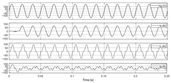
Figure 12.
Grid voltage and current waveforms with APF, without considering control delay, showing the grid current closely following a sinusoidal waveform.
Figure 13 presents the spectral analysis of the grid current ia after the introduction of the APF. Following compensation, the THD of ia significantly decreases from 25.84% to 3.41%. This result demonstrates that the designed compensation current ig effectively suppresses the low-order harmonic components generated by the nonlinear load, markedly improving the spectral characteristics of the input current. Consequently, the proposed APF control strategy exhibits excellent harmonic mitigation capability, providing a substantial enhancement in both power quality and overall system stability.
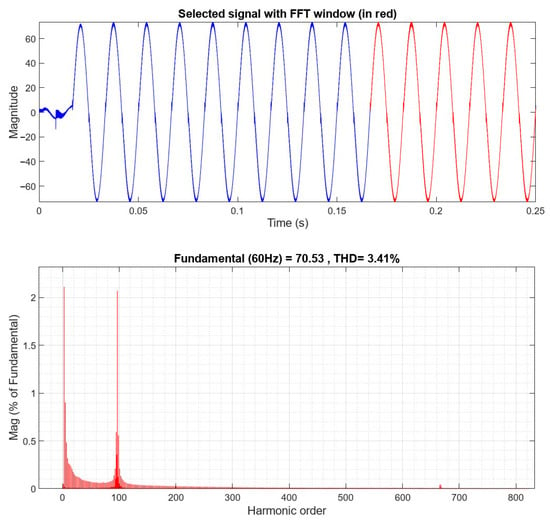
Figure 13.
Frequency-domain spectrum of the grid current with APF, showing effective harmonic suppression without considering control delay.
3.3. Scenario 3-APF with Digital Control Delay
Figure 14 illustrates the time-domain responses of voltages and currents when the system considers the effect of control delay. As shown, the grid voltage vg remains an ideal sinusoidal waveform, indicating that the input is unaffected by the delay. The load current iL also maintains stable oscillation amplitude. However, both the grid current ia and the compensation current ig exhibit noticeable divergent behavior, with amplitudes rapidly increasing over time, potentially leading to system instability or collapse. This unstable phenomenon is primarily attributed to the introduction of control delay in the digital control system, which effectively adds extra phase lag in the current feedback path. The delay significantly reduces the system’s PM, causing the poles of the open-loop transfer function to move toward the right half-plane and even cross the imaginary axis, resulting in an unstable closed-loop system. These simulation results clearly demonstrate the severe impact of control delay on system stability and underscore the necessity of a delay compensation mechanism. As the resulting grid current THD becomes extremely large in this scenario, it loses physical significance; therefore, the system stability is evaluated primarily through the time-domain responses, providing a more meaningful assessment of performance under extreme conditions.
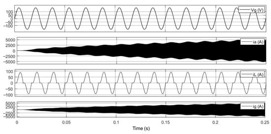
Figure 14.
Time-domain responses of grid voltage and currents with APF under control delay effects, showing the grid current becoming unstable over time.
3.4. Scenario 4-APF with Proposed Delay Compensation
Figure 15 illustrates the current waveforms when the APF system incorporates the proposed control delay compensation strategy. It can be observed that the grid voltage Vg remains stable and undistorted, indicating that the power network side is unaffected by the control adjustments. Compared to the uncompensated case, the compensated grid current ia clearly restores a sinusoidal waveform that is in phase with the grid voltage, successfully achieving power factor correction and demonstrating the effective harmonic suppression of the compensation mechanism. Moreover, the compensation current ig exhibits a stable and convergent behavior without any divergence, showing that the compensator possesses robust dynamic regulation capability, capable of promptly counteracting the harmonics and non-ideal components in the load current iL. Overall, these results verify that the proposed control delay compensation strategy significantly enhances the system’s stability and current quality.
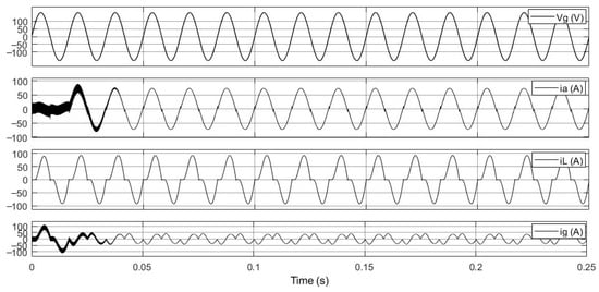
Figure 15.
Grid voltage and current waveforms with control delay compensation, showing the grid current closely following a sinusoidal waveform.
Figure 16 presents the frequency spectrum of the grid current ia after implementing the control delay compensation mechanism in the APF system. The FFT analysis shows a significant improvement in THD, which decreases to 4.99%, indicating that the delay compensation strategy effectively mitigates instability caused by control delays. The simulation results demonstrate that the compensated current THD is under 5%, verifying the high feasibility and practicality of the proposed compensation mechanism in improving current quality.
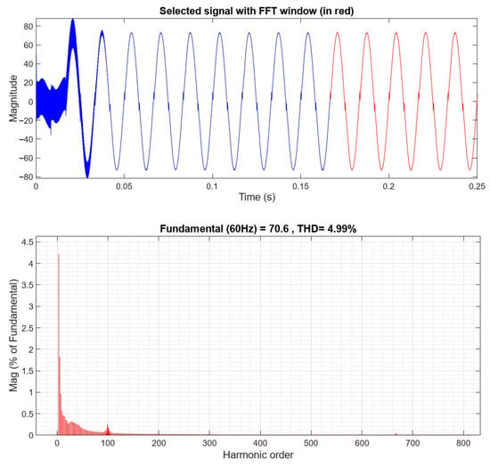
Figure 16.
Frequency-domain spectrum of the grid current with control delay compensation applied, showing effective harmonic suppression.
Unlike previous studies based on conventional LCL filters, our work employs an LLCL-type filter as the system foundation, which introduces additional resonance points and significantly increases control complexity. The proposed delay compensation method robustly ensures stable operation of this more challenging LLCL system, effectively mitigating control delays while suppressing multi-resonant behaviors. This demonstrates a decisive advantage over traditional approaches: our method achieves stable performance in a system inherently more difficult to control, without requiring additional sensors, predictive controllers, or complex modifications.
4. Conclusions
This study addresses the issue of current harmonic pollution caused by rectifier-type loads by designing an APF system integrated with a control delay compensation mechanism. The system employs an LLCL filter topology, which, owing to its superior high-frequency attenuation characteristics and potential for compact modular design, effectively enhances overall filtering performance. From a control perspective, the inherent computation and PWM delays in digital control systems are explicitly modeled, and a negative-feedback delay compensator is designed to improve system stability and phase margin under dynamic operating conditions. Simulation analyses are conducted under four operational scenarios: a baseline system without APF, an APF system without considering delay, an APF system with delay but without compensation, and the complete system with the delay compensator implemented. Results indicate that, without delay compensation, the system exhibits divergent responses, as illustrated by the rapidly increasing amplitudes in the grid and compensation currents, demonstrating system instability. With the proposed delay compensation mechanism, the waveforms show significant improvement, the control response converges stably, and the final current THD is reduced to 4.99%. In this study, the THD of the grid current is employed as the performance metric for evaluating harmonic suppression. Under the given simulation conditions, the compensated system achieves a grid current THD well below 5%, demonstrating effective mitigation of harmonic distortion. These results validate the effectiveness of the proposed LLCL-type APF architecture and the delay compensation strategy in improving power quality.
Furthermore, we also briefly discuss the practical implementation and potential limitations of the proposed method. The delay compensation strategy is straightforward to implement, requiring no additional sensors or predictive controllers, making it suitable for typical LLCL-type APF systems. Its effectiveness depends on accurate knowledge of system parameters, and performance may be sensitive to variations or uncertainties in these parameters.
In future work, we plan to further extend the proposed LLCL-type APF control strategy to address additional practical scenarios. Specifically, studies will explore its application to systems with variable switching frequencies and multi-phase grid-connected converters, aiming to further enhance robustness and practical applicability. While experimental implementation would provide additional verification, the primary focus of the current and near-term studies remains on comprehensive simulation-based analysis, which has already demonstrated the method’s effectiveness under a wide range of operating conditions. These future investigations will continue to deepen understanding of the proposed delay compensation strategy and its potential for broader practical deployment.
Author Contributions
Conceptualization, T.-C.C. and P.-S.L.; methodology, T.-C.C.; formal analysis, T.-C.C. and P.-S.L.; investigation, P.-S.L. and C.-Y.C.; resources, T.-C.C.; data curation, P.-S.L. and C.-Y.C.; writing—original draft preparation, T.-C.C.; writing—review and editing, C.-W.H.; visualization, P.-S.L.; supervision, T.-C.C.; project administration, T.-C.C.; funding acquisition, T.-C.C. All authors have read and agreed to the published version of the manuscript.
Funding
This research was funded by the National Science and Technology Council (NSTC), grant number 113-2222-E-239-003-.
Data Availability Statement
The datasets generated and/or analyzed during the current study are available from the corresponding author upon reasonable request.
Conflicts of Interest
The authors declare no conflicts of interest.
References
- Luo, A.; Xu, Q.M.; Ma, F.J.; Chen, Y.D. Overview of power quality analysis and control technology for the smart grid. J. Mod. Power Syst. Clean Energy 2016, 4, 1–9. [Google Scholar] [CrossRef]
- Fei, J.T.; Wang, H. Experimental Investigation of Recurrent Neural Network Fractional-Order Sliding Mode Control of Active Power Filter. IEEE Trans. Circuits Syst. II Express Br. 2020, 67, 2522–2526. [Google Scholar] [CrossRef]
- Gao, C.; He, S.; Fang, X.F.; Davari, P.; Leung, K.N.; Loh, P.C.; Blaabjerg, F. Current-Limiting Control Strategy for Indirect-Current-Controlled Active Power Filter. IEEE Trans. Power Deliv. 2024, 39, 3551–3554. [Google Scholar] [CrossRef]
- Karbasforooshan, M.S.; Monfared, M. Adaptive Self-Tuned Current Controller Design for an LCL-Filtered LC-Tuned Single-Phase Shunt Hybrid Active Power Filter. IEEE Trans. Power Deliv. 2022, 37, 2747–2756. [Google Scholar] [CrossRef]
- Indragandhi, V.; Boopathi, R. Experimental Investigations on Photovoltaic Interface Neutral Point Clamped Multilevel Inverter-Based Shunt Active Power Filter to Enhance Grid Power Quality. IEEE Access 2024, 12, 74482–74498. [Google Scholar] [CrossRef]
- Rai, K.B.; Kumar, N.; Singh, A. Three-Phase Grid Connected Shunt Active Power Filter Based on Adaptive Q-LMF Control Technique. IEEE Trans. Power Electron. 2024, 39, 10216–10225. [Google Scholar] [CrossRef]
- Xin, Z.; Wang, X.F.; Loh, P.C.; Blaabjerg, F. Grid-Current-Feedback Control for LCL-Filtered Grid Converters with Enhanced Stability. IEEE Trans. Power Electron. 2017, 32, 3216–3228. [Google Scholar] [CrossRef]
- Ding, X.; Xue, R.N.; Zheng, T.Z.; Kong, F.N.; Chen, Y.M. Robust Delay Compensation Strategy for LCL-Type Grid-Connected Inverter in Weak Grid. IEEE Access 2022, 10, 67639–67652. [Google Scholar] [CrossRef]
- Wu, W.; Wang, W.G. Research on FCS-MPC Control of LCL Grid-Connected Inverter Based on Optimized i1-i2-uc Prediction. In Proceedings of the 2019 International Conference on Computer Network, Electronic and Automation, Xi’an, China, 27–29 September 2019. [Google Scholar]
- Lin, Z.H.; Ruan, X.B.; Zhang, H.; Wu, L.G. A Generalized Real-Time Computation Method with Dual-Sampling Mode to Eliminate the Computation Delay in Digitally Controlled Inverters. IEEE Trans. Power Electron. 2022, 37, 5186–5195. [Google Scholar]
Disclaimer/Publisher’s Note: The statements, opinions and data contained in all publications are solely those of the individual author(s) and contributor(s) and not of MDPI and/or the editor(s). MDPI and/or the editor(s) disclaim responsibility for any injury to people or property resulting from any ideas, methods, instructions or products referred to in the content. |
© 2025 by the authors. Licensee MDPI, Basel, Switzerland. This article is an open access article distributed under the terms and conditions of the Creative Commons Attribution (CC BY) license (https://creativecommons.org/licenses/by/4.0/).