1. Introduction
The advent of 6G technology is expected to bring revolutionary advancements to the Internet of Things (IoT) [
1,
2], especially in low-power IoT scenarios such as massive Machine Type Communication (mMTC) [
3], where low PAPR is a critical performance metric that directly influences device energy consumption [
4]. Enhanced coverage is another key scenario in 6G, in which low PAPR also plays a vital role. Techniques aimed at reducing PAPR typically include low PAPR waveform design [
5,
6], low PAPR modulation schemes [
7,
8,
9], and various signal preprocessing methods [
10,
11]. These approaches have the potential to improve energy efficiency, extend battery life [
12,
13], and enhance uplink coverage. As such, low PAPR technologies are of significant importance in the development of 6G, particularly for low-power IoT and extended coverage applications, and are currently under active research for potential standardization.
In existing communication systems, OFDM has been widely adopted due to its ability to mitigate frequency-selective fading in multipath channels and its relatively low implementation complexity at both the transmitter and receiver. However, in multi-carrier OFDM systems, the PAPR increases due to the superposition of multiple subcarriers within the same time-domain symbol, which can significantly degrade system performance [
14]. Generally, single-carrier waveforms exhibit lower PAPR compared to multi-carrier waveforms [
15]. For instance, the DFT-s-OFDM waveform used in 5G NR typically achieves a lower PAPR owing to the application of DFT processing prior to OFDM modulation. The PAPR of single-carrier waveforms is strongly influenced by the modulation scheme. Currently, the 5G mobile communication standard supports π/2-BPSK modulation, which offers relatively low PAPR. Nevertheless, meeting the even stricter PAPR requirements for future 6G signal applications remains a significant challenge.
On the other hand, the industry has also adopted FDSS for π/2-BPSK [
16,
17] as an implementation approach to further reduce PAPR. However, this method compromises demodulation performance. Several other low PAPR modulation schemes have also been proposed, including 8-BPSK [
18], Continuous Phase Modulation (CPM) [
19], and trellis-coded QPSK [
20]. In 8-BPSK, information bits are mapped onto 8-PSK constellation points using a grid-based mapping method to ensure minimal phase transitions between consecutive symbols. CPM, as a phase modulation technique, employs cumulative and instantaneous phase components to achieve near-continuous phase transitions. As a common novel modulation scheme in 5G NR proposals, trellis-coded QPSK is characterized by its low PAPR, resulting from the joint design of convolutional codes and QPSK mapping. Nevertheless, these schemes still face challenges such as degraded demodulation performance at the receiver and increased demodulation complexity, which significantly limit their practical applicability. Additionally, in [
21], a (1 + D) π/2(N + 1) BPSK scheme was proposed, capable of achieving very low PAPR while preserving good demodulation performance. However, as N increases, the required code rate decreases, which limits its efficiency in high-data-rate scenarios.
So far, no existing scheme has demonstrated superior overall performance compared to the π/2-BPSK scheme when considering key factors such as PAPR, BLER, and receiver complexity. Therefore, it is of great importance for future communication systems to develop a modulation scheme that achieves a lower PAPR without compromising other performance characteristics.
This article proposes a novel ORIM scheme designed to meet the stringent PAPR requirements expected in 6G communications. ORIM is an interpolation-based modulation technique that combines cyclic shifting and phase rotation, employing QPSK, BPSK, and π/2-BPSK as base modulation formats. Importantly, ORIM achieves a substantial reduction in PAPR without sacrificing demodulation performance, making it a promising candidate for future 6G systems.
The structure of the article is organized as follows:
Section 2: Explains the fundamental principles of ORIM, including the overarching concept and the detailed generation process for each ORIM variant. This section also provides a comparative analysis of PAPR performance between ORIM and existing modulation schemes, quantitatively demonstrating its advantages.
Section 3: Introduces three distinct demodulation algorithms specifically designed for ORIM. The analysis shows that ORIM achieves significantly low demodulation complexity.
Section 4: Presents a comprehensive comparison of the BLER performance across the three ORIM variants. Simulation results confirm that there is no noticeable BLER degradation compared to conventional modulation schemes.
2. Modulation Scheme of ORIM
As shown in
Figure 1a, the overall scheme of ORIM can be described as follows: modulate the bit data to generate a first data sequence, then perform cyclic offset and addition operations on the first data sequence sequentially to generate a second data sequence. Each element of the phase-rotated second data sequence is inserted between adjacent elements of the first data sequence to form a third data sequence. This third data sequence is the modulated data sequence for ORIM.
The specific process for generating the second data sequence is as follows: the real and imaginary parts of the first data sequence are respectively obtained as the fourth and fifth data sequences. Then, the cyclic offset is applied to the fourth data sequence, and the second data sequence is formed by adding it to the fifth data sequence. Here, the cyclic offset can also be applied to the fifth data sequence (imaginary parts). Essentially, it is the same. In this article, we only take the cyclic offset of the fourth data sequence as an example.
The specific process of phase rotation of the second data sequence is to rotate each element of the second data sequence with phase θ in turn, that is, multiply by exp(jθ), in which “exp(·)” represents the natural exponential function and j is the imaginary unit. When the modulation scheme of the first data sequence is QPSK or BPSK, θ equals 0 or π; and when the system is a single-carrier DFT-s-OFDM system, if the time-domain modulated symbols are directly mapped to the frequency-domain resources in the order of subcarriers after performing DFT, θ equals π, in this case, the serial number of the subcarrier is 0 to P-1, P is the total number of the subcarriers; if the time-domain modulated symbols are first subjected to DFT and then undergo a half-cycle offset, and then mapped to the frequency-domain resources in the order of subcarriers, θ equals 0, in this case, the serial number of the subcarrier is −P/2 to P/2 − 1. When the modulation scheme of the first data sequence is π/2 BPSK, θ equals ±π/4 when a half-cycle offset is performed and θ equals ±3π/4 when a half-cycle offset is not performed. The descriptions in the remainder of this article are all for the case where a half-cycle offset is performed.
Among them, when the modulation methods of the first sequence are QPSK, BPSK, or π/2 BPSK, respectively, the generated ORIMs are I-QPSK, I-BPSK, and I-π/2 BPSK.
The above process can be summarized as generating
s(
m) according to Equation (1),
m = 1, 2, 3,…,
M, where
M is the number of elements in the
s(
m) sequence. The
C(
n) sequence is the data sequence of QPSK, BPSK, and π/2 BPSK modulation, i.e., the first data sequence,
n = 1, 2, 3,…,
N, where
N is the number of elements in the
C(
n) sequence, and
M = 2
N. Where “real(·)” represents taking the real part, “imag(·)” represents taking the imaginary part, and
θ(
m) is the rotating phase. In the formula for generating
s(
M),
C(
N + 1) is the first data in the
C(
n) sequence, i.e.,
C(
N + 1) =
C(1). Equation (1) is to take the imaginary part of the former symbol and the real part of the latter symbol, and can also be reversed, that is, to take the real part of the former symbol and the imaginary part of the latter symbol.
This process can also be described by the diagram in
Figure 1b, where switches S1 and S2 are used to generate the odd and even symbols of data, respectively. Specifically, S1 corresponds to the first line of Equation (1) and is used to generate the original modulation data (QPSK, BPSK, or π/2-BPSK), whereas S2 corresponds to the second line of Equation (1) and generates the data after cyclic offset and phase rotation. The final ORIM is then obtained by inserting the even symbols into the sequence of odd symbols. Algorithm 1 summarizes the detailed process by which ORIM generates data.
| Algorithm 1: ORIM Sequence Generation |
| Input: bit_data, mod_type: (QPSK, BPSK, π/2-BPSK), θ, |
| 1: first_seq (length N) ← Modulation(bit_data, mod_type) |
| 2: real_part ← Re(first_seq); imag_part ← Im(first_seq) |
| 3: shifted_real ← Cyclic_Shift(real_part, 1) |
| 4: second_seq ← shifted_real + j·imag_part |
| 5: switch mod_type: |
| case QPSK or BPSK: θ ← {0, π} |
| case π/2-BPSK: θ ← {±π/4, ±3π/4} |
| 6: rotated_second_seq ← second_seq·exp(jθ) |
| 7: for i ← 1 to N-1 do: |
| ORIM_seq.append(first_seq[i]) |
| ORIM_seq.append(rotated_second_seq[i]) |
| end for |
| ORIM_seq.append(first_seq[N]) |
| 8: Output: ORIM_seq |
We can clearly identify the differences between ORIM and the (1 + D) π/2(N + 1) BPSK schemes in [
21], that is, ORIM is not merely interpolation; it also encompasses cyclic offset and phase rotation, and ORIM can be generated based on BPSK, QPSK, or even 16QAM or others.
The following section will present an overview of three types of ORIM processes along with their associated constellation diagrams.
2.1. I-QPSK
The I-QPSK scheme can be obtained by performing the following processing steps.
According to the description of QPSK in 3rd Generation Partnership Project (3GPP) TS38.211 protocol [
22], a length-
N first data sequence {
C1,
C2,…,
CN} is generated by performing QPSK modulation on 2
N bits of data {
b1,
b2,…,
b2N}:
where
n = 1, 2, 3,…,
N, and j is the imaginary unit.
First, extract the real parts {
I1,
I2,…,
IN} and imaginary parts {
Q1,
Q2,…,
QN} of the first data sequence as the fourth and fifth data sequences, respectively. Then, perform a left cyclic offset on the fourth data sequence to obtain {
I2,
I3,…,
IN,
I1}. Next, add this offset sequence with the fifth data sequence to generate a second data sequence of length
N: {
I2 +
Q1,
I3 +
Q2,…,
IN +
QN-1,
I1 +
QN}. In this case, we are considering
θ = 0, so the phase rotation operation can be omitted. Insert these elements sequentially between adjacent elements in the first data sequence to form a third data sequence of length 2
N: {
I1 +
Q1,
I2 +
Q1,
I2 +
Q2,
I3 +
Q2,…,
IN +
QN-1,
IN +
QN,
I1 +
QN}. This results in an I-QPSK modulated data sequence. It is worth noting that the interpolation results of I-QPSK can be generated based on left or right cyclic offset of the real part, and these two schemes have the same performance and PAPR. The example provided in this article is a left cyclic offset; this is equivalent to (1 + D) π/2 BPSK in article [
21], but the right cyclic offset is not. The constellation diagram for I-QPSK is shown in
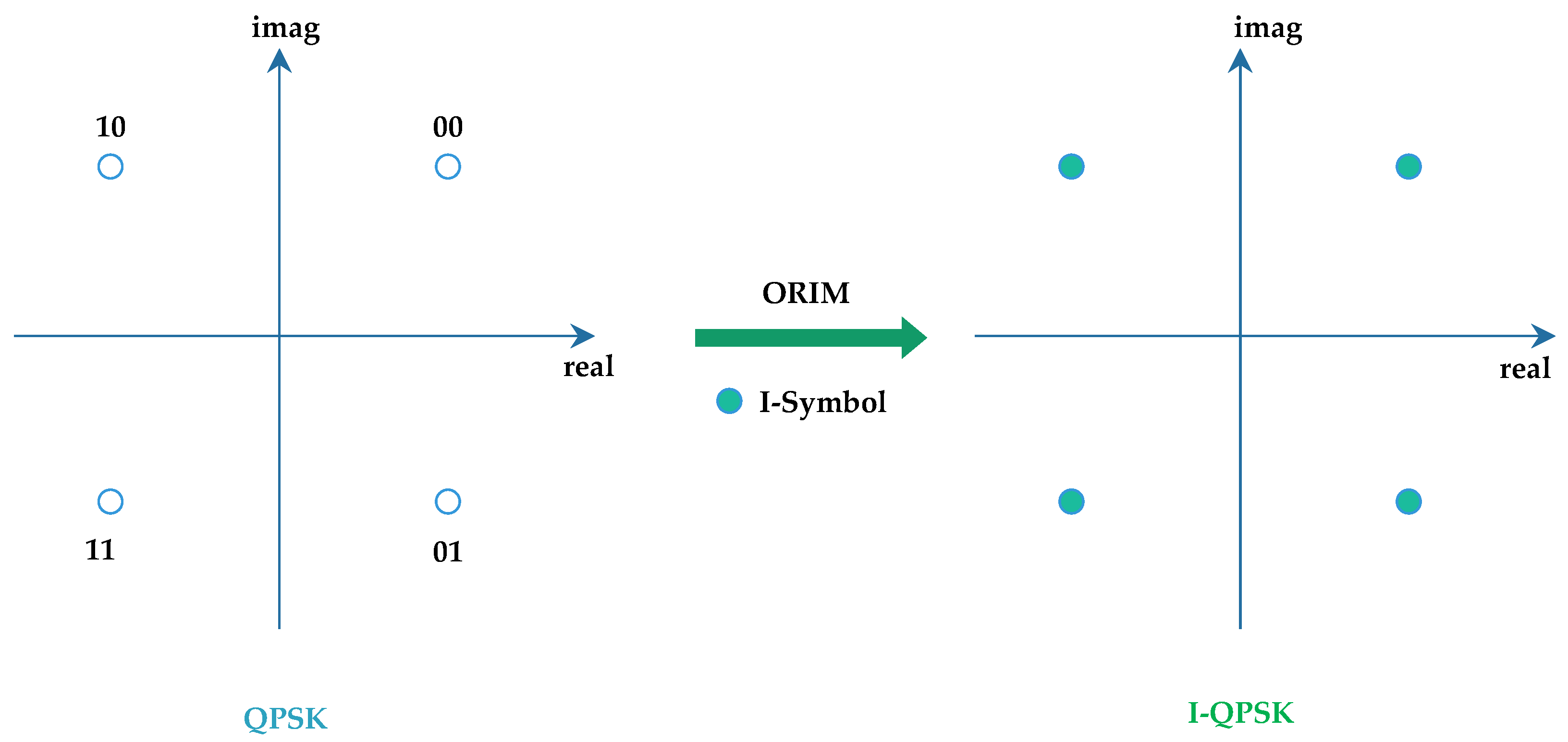
Figure 2. The odd symbols of I-QPSK are the QPSK symbols, the even symbols are obtained by QPSK cyclic offset and phase rotation, and the constellation diagram is exactly these four points, so the constellation diagram after interpolation is the same as the constellation diagram of QPSK. However, the generation process and meaning of constellation points of even symbols and constellation points of QPSK are different.
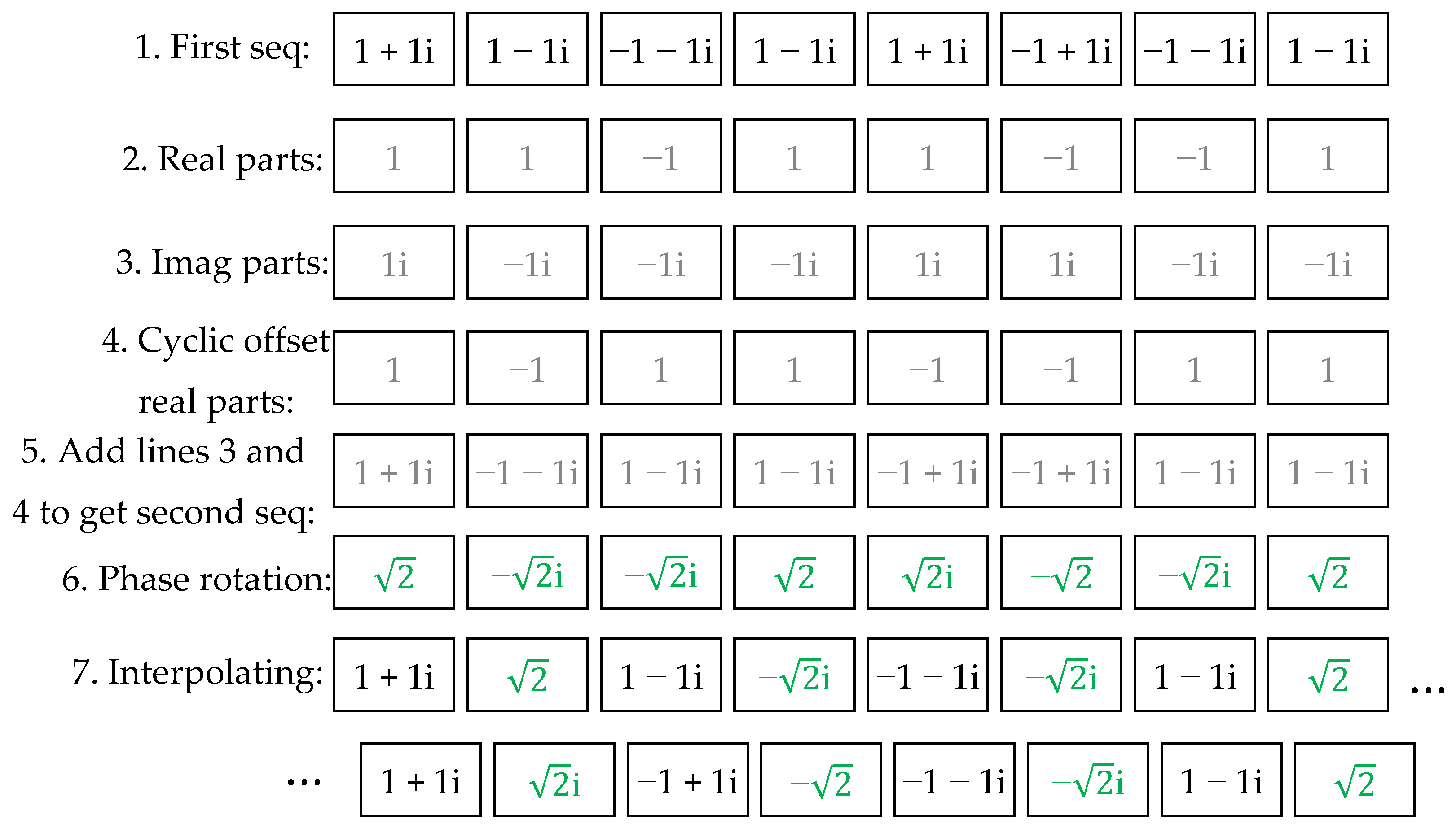
Figure 3 presents a schematic diagram of I-QPSK generation, where the issue of power was ignored for convenience. It can be observed that because the I-QPSK generation process can ensure that two adjacent symbols have the same real part or imaginary part, the phase variations between adjacent symbols in I-QPSK are either 0 or π/2, whereas in conventional QPSK, the phase variations can be 0, π/2, or π. This illustrates that ORIM can effectively reduce the phase variations between adjacent symbols, thereby lowering the PAPR.
It should be noted that the trellis-coded QPSK mentioned in [
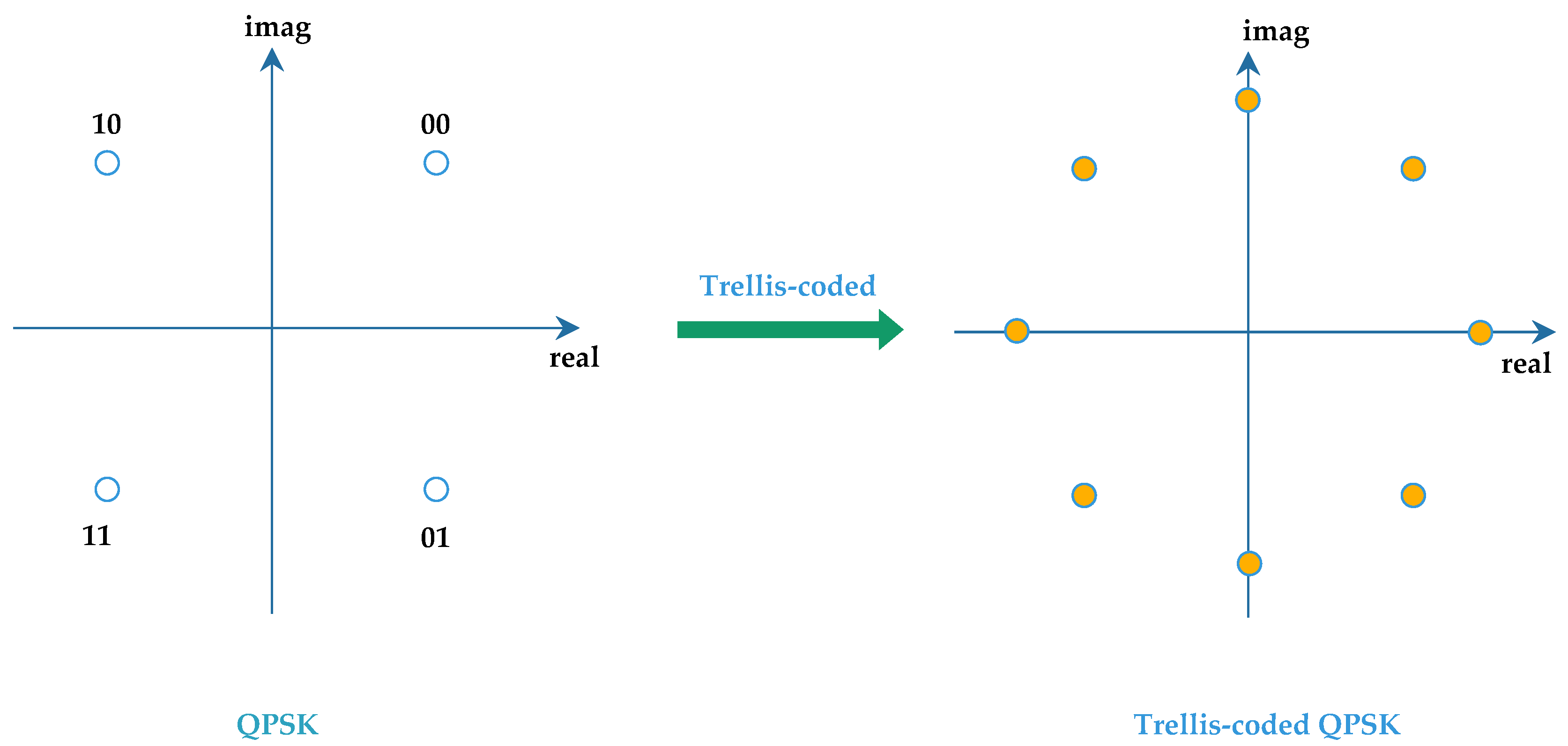
20] and the proposed I-QPSK in this article are two different modulation methods. In simple terms, it can be observed from the constellation diagram of trellis-coded QPSK, as shown in
Figure 4, that it contains 8 different constellation points, while the proposed I-QPSK only has 4 different constellation points.
2.2. I-BPSK
The I-BPSK scheme can be obtained through the following processing steps.
The
N-bit data {
b1,
b2,…,
bN} is modulated using BPSK to generate a first data sequence of length
N: {
C1,
C2,…,
CN}. According to the description of BPSK in 3GPP’s TS38.211 protocol.
where
n = 1, 2, 3,…,
N, and j is the imaginary unit.
The real part {
I1,
I2,…,
IN} and the imaginary part {
Q1,
Q2,…,
QN} of the first data sequence are separately obtained as the fourth data sequence and the fifth data sequence. Then, a left cyclic offset is performed on the fourth data sequence to obtain {
I2,
I3,…,
IN,
I1}. After that, an addition operation is carried out with the aforementioned fifth data sequence to generate a second data sequence of length
N as {
I2 +
Q1,
I3 +
Q2,…,
IN +
QN-1,
I1 +
QN}. In this case, we are considering
θ = 0, so the phase rotation operation can be omitted. Then, each element in it is inserted sequentially between adjacent elements of the first data sequence to form a third data sequence of length 2
N as {
I1 +
Q1,
I2 +
Q1,
I2 +
Q2,
I3 +
Q2,…,
IN +
QN-1,
IN +
QN,
I1 +
QN}, which represents an I-BPSK modulated signal. The interpolation result of I-BPSK can be generated based on left or right cyclic offset of the real part, and both schemes exhibit equivalent performance and PAPR characteristics. In this article, an example demonstrating a left cyclic offset is provided. The constellation diagram for I-BPSK modulation is shown in
Figure 5.
Figure 6 presents a schematic diagram of I-BPSK generation, where the issue of power was ignored for convenience. It can be observed that because the I-BPSK generation process can ensure that two adjacent symbols have the same real part or imaginary part, the phase variations between adjacent symbols in I-BPSK are either 0 or π/2, whereas in conventional BPSK, the phase variations can be 0 or π. This illustrates that ORIM can effectively reduce the phase variations between adjacent symbols, thereby lowering the PAPR.
2.3. I-π/2 BPSK
The I-π/2 BPSK scheme can be achieved through the following processing steps.
The
N-bit data {
b1,
b2,…,
bN} is modulated using π/2-BPSK to generate
N first data sequences {
C1,
C2,…,
CN}. According to the description of π/2-BPSK in 3GPP’s TS38.211 protocol, it can be understood that:
where
n = 1, 2, 3,…,
N, and j is the imaginary unit, “(
n − 1) mod 2” means the remainder when (
n − 1) is divided by 2.
First, obtain the real part {
I1,
I2,…,
IN} and the imaginary part {
Q1,
Q2,…,
QN} of the first data sequence as the fourth and fifth data sequences, respectively. Then, perform a left cyclic offset on the fourth data sequence to obtain {
I2,
I3,…,
IN,
I1}. Next, add this offset sequence with the fifth data sequence to generate a second data sequence of length
N: {
I2 +
Q1,
I3 +
Q2,…,
IN +
QN-1,
I1 +
QN}. In this case, we are considering phase rotation
θ = ±π/4, so multiply each element in the second data sequence by a phase correction coefficient {exp(-jπ/4), exp(jπ/4),…, exp((-1)
Njπ/4)}. Then, insert each resulting element between adjacent elements in the first data sequence to form a third data sequence of length 2
N: {
I1 +
Q1, exp(-jπ/4)(
I2 +
Q1),
I2 +
Q2, exp(jπ/4)(
I3 +
Q2),…, exp((−1)
N−1jπ/4)(
IN +
QN−1),
IN +
QN, exp((−1)
Njπ/4)(
I1 +
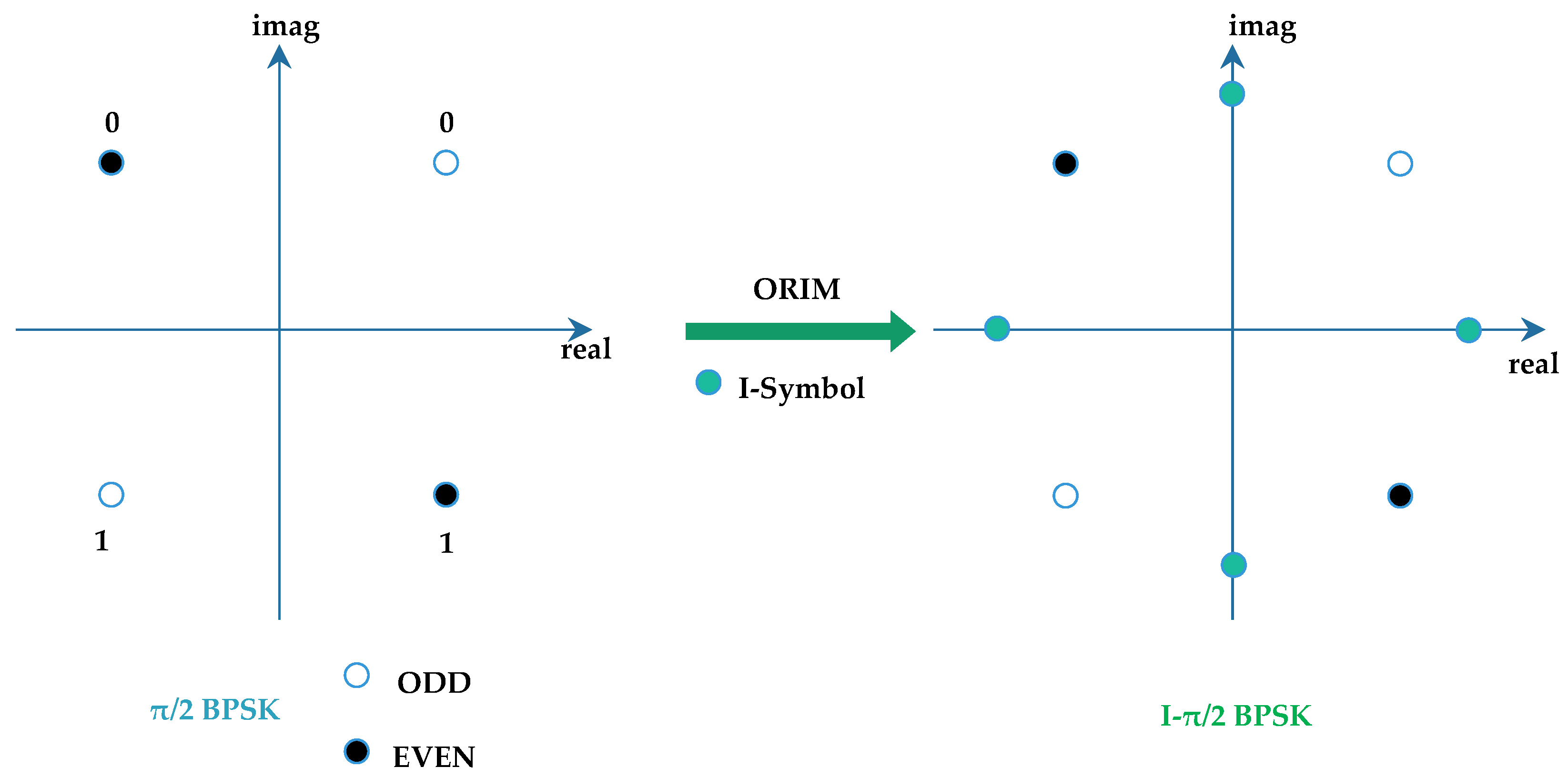
QN)}. This results in an I-π/2 BPSK modulated data sequence, which can also be named π/4 BPSK. The name “π/4 BPSK” is given because it involves phase correction coefficients related to π/4, and adjacent modulation symbols have a phase difference of π/4. The interpolation result for I-π/2 BPSK can be achieved through either left or right cyclic offset of the real part; this article provides an example using left cyclic offset, but both methods yield identical modulation schemes. The constellation diagram for I-π/2 BPSK is shown in
Figure 7.
Figure 8 presents a schematic diagram of I-π/2 BPSK generation, where the issue of power was ignored for convenience. It can be observed that because the I-π/2 BPSK generation process can ensure that two adjacent symbols have the same real part or imaginary part before phase rotation, the phase variations between adjacent symbols in I-π/2 BPSK are π/4, whereas in conventional π/2 BPSK, the phase variations can be π/2. This illustrates that ORIM can effectively reduce the phase variations between adjacent symbols, thereby lowering the PAPR.
2.4. PAPR Analysis
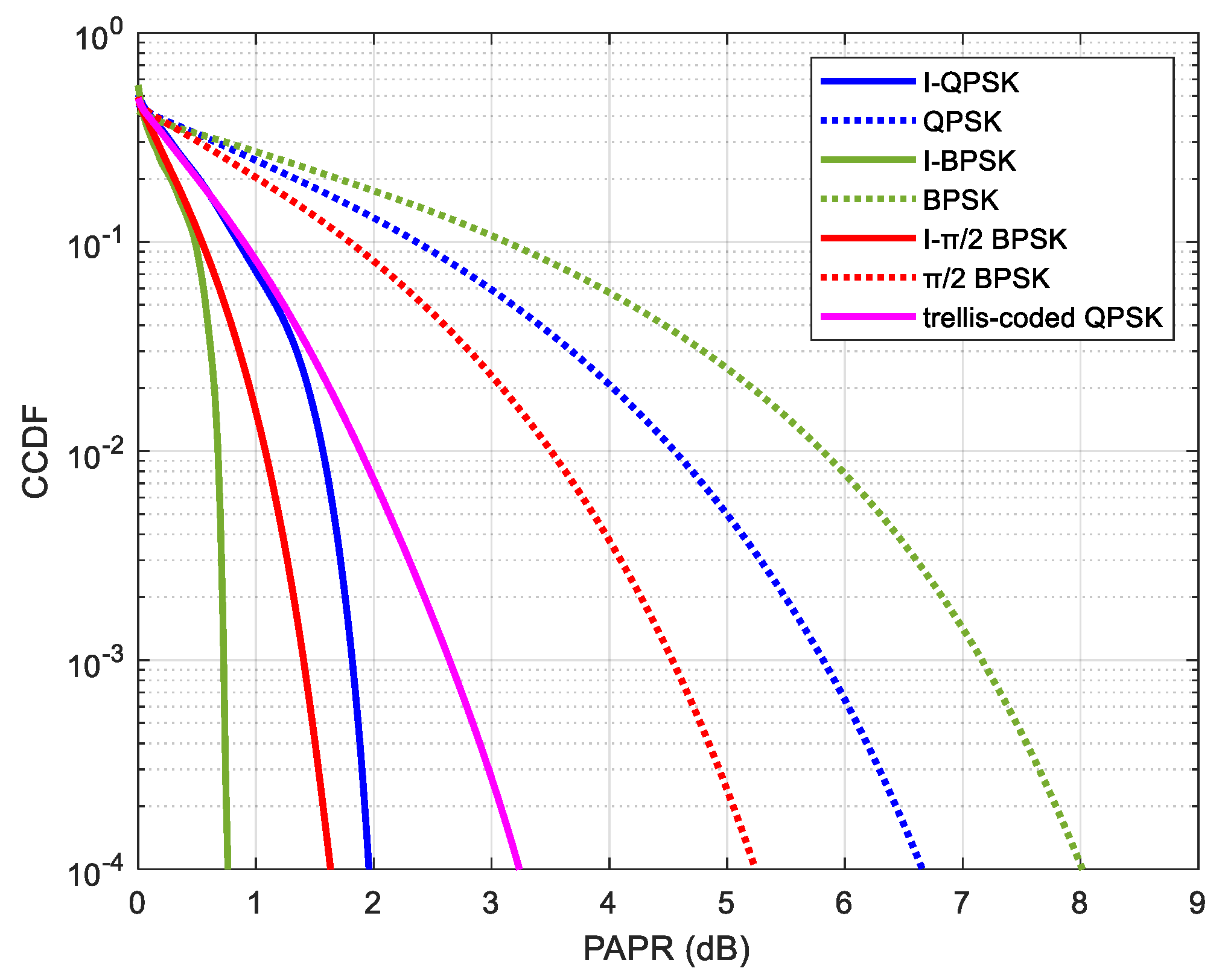
The comparative simulation results of the PAPR are shown in
Figure 9 for I-QPSK, I-BPSK, and I-π/2 BPSK, as well as the existing schemes of π/2 BPSK and the trellis-coded QPSK.
We adopt the method of Complementary Cumulative Distribution Function (CCDF) to analyze the PAPR performance of the signal. The complementary cumulative distribution function of the ratio between the instantaneous power and mean power of signal
x is calculated using Equation (5).
Among them, “
P(·)” represents the probability that satisfies the condition in parentheses, and “
E(·)” denotes taking the average.
xpapr is the linear value of PAPR, which is converted to dB units and corresponds to the horizontal axis values in
Figure 6, while
fCCDF (
xpapr) represents the vertical axis values.
We conducted PAPR simulations to compare various modulation schemes under the following simulation parameters: 1 Resource Block (RB), which is 12 subcarriers [
23] and DFT-s-OFDM waveforms. The PAPR of DFT-S-OFDM is independent of the data bandwidth and is only related to the modulation scheme. The results in
Figure 9 demonstrate that the proposed three ORIM schemes for PAPR have lower PAPR compared to the π/2 BPSK PAPR in the 5GNR protocol. This occurs because ORIM generation yields smaller phase transitions between adjacent modulation symbols in the time domain compared to BPSK or QPSK, thereby reducing PAPR in oversampled data. This is because determining the PAPR is fundamentally equivalent to calculating the PAPR of a continuous analog signal, which is generated by oversampling the discretized modulated symbol data and is also the input signal of the Power Amplifier (PA). The greater the positive correlation among the modulation symbols before oversampling, the lower the resulting PAPR. Moreover, when the signal magnitudes are equal, smaller phase variations result in stronger positive correlation, thereby leading to a lower PAPR.
It is evident that the modulation process of the ORIM transmitter is not significantly complex compared to π/2 BPSK. Moreover, the power consumption of this component is considerably lower than that of DFT or the gains achieved through PAPR reduction.
Additionally, the proposed I-QPSK also exhibits lower PAPR than the trellis-coded QPSK mentioned in [
20].
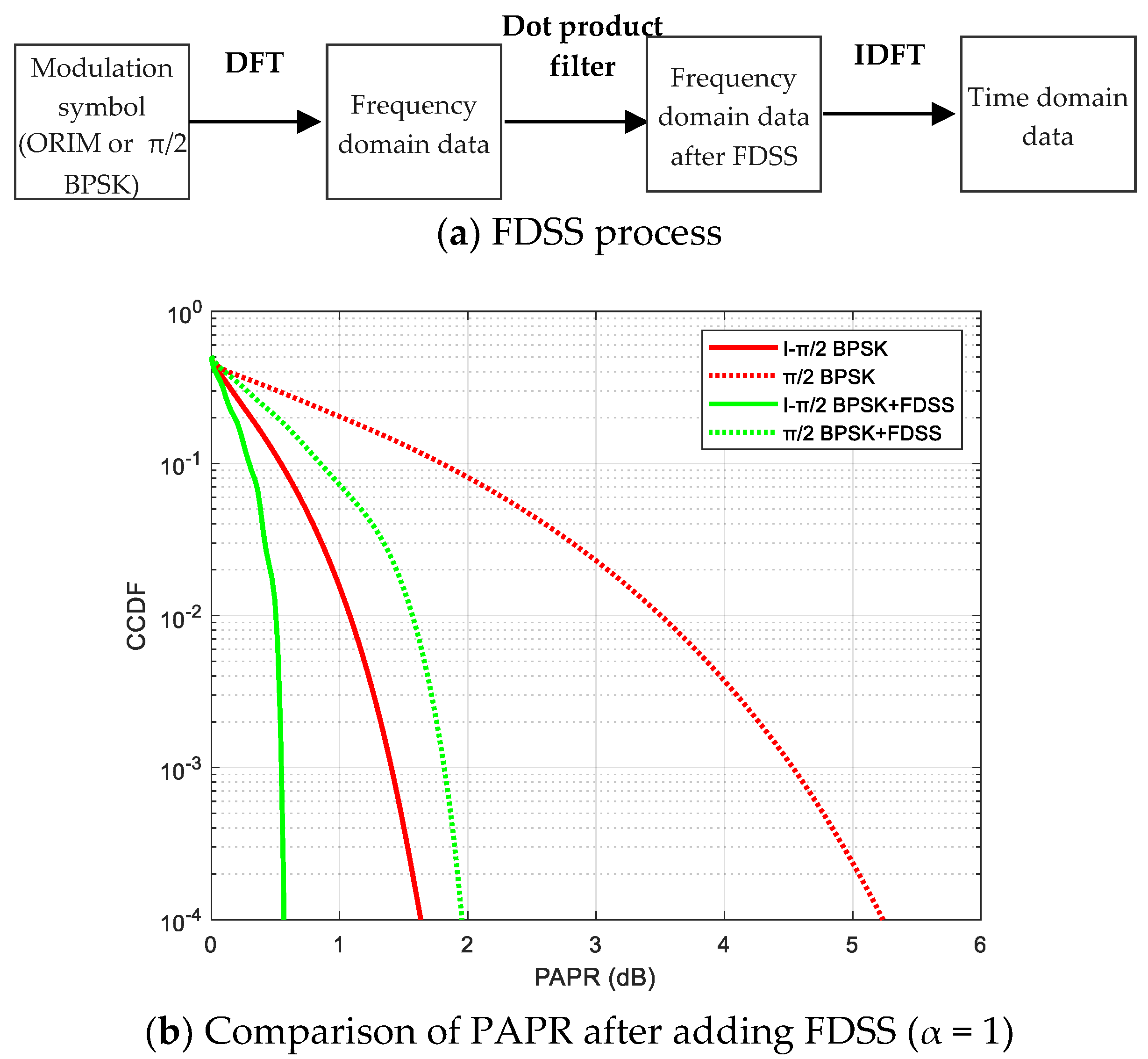
In the 5G NR implementation, a filtering operation known as FDSS can be applied to the transmitted data, which reduces the PAPR of π/2 BPSK. Therefore, in this case, we compare the PAPR of I-π/2 BPSK and π/2 BPSK with the same FDSS. The process of FDSS can be summarized as shown in
Figure 10a. First, FFT is performed on the data of the modulation symbol to obtain the frequency-domain data, and then it is multiplied with a root-raised cosine (RRC) filter in the frequency domain. The bandwidth of the RRC filter is equal to the frequency-domain width of the data, and the roll-off factors α = 1 is chosen for the filter. Finally, IFFT is performed on the frequency-domain data after FDSS to obtain the time-domain data.
The results shown in
Figure 10 demonstrate that after adding identical FDSS, our proposed I-π/2 BPSK has lower PAPR compared to π/2 BPSK in the 5G NR protocol, where the gains are approximately 1.4 dB at CCDF = 10
−4.
In addition, we have provided
Table 1 to more clearly display the SNR values of the PAPR results of several modulation methods at CCDF = 10
−4, facilitating performance comparison.
3. Demodulation Scheme of ORIM
This chapter will introduce three receiver demodulation algorithms for ORIM, with the main principle being the Log-likelihood ratio (LLR) algorithm [
24,
25].
3.1. Demodulation Scheme for I-QPSK
First, let us introduce the demodulation scheme for I-QPSK. Based on the modulation scheme at the transmitter end of I-QPSK, it can be observed that each bit of information is related to two adjacent modulation symbols. Specifically, for odd-numbered bits b2n-1, they determine the real part of the (2n − 2)-th and (2n − 1)-th modulation symbols in the third data sequence; while for even-numbered bits b2n, they determine the imaginary part of the (2n − 1)-th and (2n)-th modulation symbols in the third data sequence. Here, n = 1, 2, 3,…, N. The value of 2N represents both a group of bits to be demodulated and a group of modulation symbols to be demodulated. In particular, when n = 1 corresponds respectively to the (2N)-th and first modulation symbol.
Therefore, in order to obtain soft information for each bit, we can use the LLR algorithm.
For ease of description, the constellation points for I-QPSK are numbered as shown in
Figure 11, and the relationship between different bits and symbols is shown in
Table 2.
The soft information of odd-numbered bits
b2n−1(
n > 1) can be obtained according to Equation (6).
In which
represents the receiver calculating the (2
n − 2)-th data symbol
s2n−2 based on the received data
y, as the sum of probabilities of symbol 2 and symbol 3 in the constellation diagram of
Figure 11.
Appendix A provides the detailed expansion of
. The same applies to others.
Substituting the expanded results into Equation (6), after simplification, we can obtain the soft information expression for bit
b2n−1.
where “real(·)” represents taking the real part, “imag(·)” represents taking the imaginary part,
σ2 represents the variance of Gaussian white noise contained in the received modulation symbol s, and similarly for other probability expressions related to
s.
Similarly, for the even-positioned bit
b2n (
n > 1):
Since I-QPSK modulation is based on the method of cyclic offset, the expression for the soft information of the first bit
b1 is as follows:
3.2. Demodulation Scheme for I-BPSK
Next, the demodulation scheme of I-BPSK will be introduced. According to the modulation scheme at the transmitting end of I-BPSK, it can be observed that each bit of information is related to three adjacent modulation symbols. Specifically, bit bn determines the real part of the (2n − 2)-th modulation symbol in the third data sequence, the overall part of the (2n − 1)-th modulation symbol, and the imaginary part of the (2n)-th modulation symbol. Here, n = 1, 2, 3,…, N. N represents the number of bits to be demodulated in a group, and 2N represents the number of modulation symbols to be demodulated in a group. In particular, when n = 1 corresponds respectively to the (2N)-th, first, and second modulation symbols.
So, to obtain the soft information for each bit, we can use the LLR algorithm.
Figure 12 shows the constellation point numbering for I-BPSK, and the relationship between different bits and symbols is shown in
Table 3.
The soft information of bit
bn (
n > 1) can be obtained according to Equation (10).
By substituting the results of all probability calculations into Equation (10) and simplifying, we can obtain the expression for the soft information of bit
bn as Equation (11).
Since I-BPSK modulation is based on the method of cyclic offset, the soft information expression for the first bit
b1 is as in Equation (12).
3.3. Demodulation Scheme for I-π/2 BPSK
Then, the demodulation scheme for I-π/2 BPSK is introduced. Based on the modulation scheme at the transmitting end of I-π/2 BPSK, it can be observed that each bit of information is related to three adjacent modulation symbols. Specifically, bit bn determines the possible mapping positions of the (2n − 2)-th, (2n − 1)-th, and (2n)-th modulation symbols in the third data sequence, here, n = 1, 2, 3,…, N. N represents the number of bits to be demodulated in a group and 2N represents the number of modulation symbols to be demodulated in a group. In particular, when n = 1 corresponds respectively to the (2N)-th, first, and second modulation symbols.
So, the soft information for each bit can be obtained using the LLR algorithm.
Figure 13 shows the constellation point numbering for I-π/2 BPSK, and the relationship between different bits and symbols is shown in
Table 4.
For odd-numbered bits
bn (
n > 1), the soft information can be obtained according to Equation (13).
By substituting the results of all probability calculations into Equation (13) and simplifying, we can obtain the expression of soft information for bit
bn as Equation (14).
For the soft information expression of even-bit
bn (
n > 1) is as Equation (15).
Since I-π/2 BPSK modulation is performed using a cyclic offset method, the soft information expression for the first bit
b1 is as in Equation (16).
In summary, the demodulation algorithms of various ORIM schemes are not complex, as they essentially involve simple addition and subtraction operations applied to the real and imaginary components. Similarly, the demodulation process of π/2-BPSK can be simplified to extracting the real and imaginary parts for computation. Therefore, it can be concluded that the demodulation complexity of ORIM is comparable to or of the same order of magnitude as that of π/2-BPSK.
Therefore, whether it is the modulation process at the transmitting end or the demodulation process at the receiving end, the complexity is very low and is much lower than the gain brought by the PAPR. It is very easy to complete for hardware implementation.
4. Simulation
In this section, the BLER performance of three types of ORIM, π/2-BPSK, and the trellis-coded QPSK is compared and analyzed under a Single-Input Single-Output (SISO) system.
Table 1 presents the simulation parameters, where each time slot contains 13 data symbols and 1 pilot symbol. To ensure fairness in comparison, that is, based on the same data rate or spectral efficiency, we have adjusted the code rate. According to modulation principles, it can be observed that I-QPSK, π/2 BPSK, and the trellis-coded QPSK have the same code rate, while I-BPSK and I-π/2 BPSK have a code rate twice that of π/2 BPSK. Based on the above modifications, all five modulation schemes have the same data bandwidth, the same spectral efficiency, and the same data rate. Due to the fact that low-power scenarios often involve narrowband transmission, such as the 1 RB bandwidth used in NB-IoT (as shown in
Table 5), its channel can be approximated as an AWGN channel. In addition, since DFT-s-OFDM is supported for low PAPR waveforms in the 5G NR protocol, DFT-s-OFDM is also used in this simulation.
In the case of the AWGN channel with ideal channel estimation, as shown in
Figure 14, simulation results indicate that the performance of the first four modulation schemes is similar, proving that ORIM does not compromise BLER performance even with a lower PAPR advantage. However, the trellis-coded QPSK exhibits slightly worse performance, and its demodulation method is more complex. Furthermore, as evidenced in
Table 1, I-QPSK, I-BPSK, and I-π/2 BPSK provide significant PAPR reduction over π/2 BPSK, with CCDF at 10
−4 gains of 3.2 dB, 4.5 dB, and 3.6 dB, respectively.
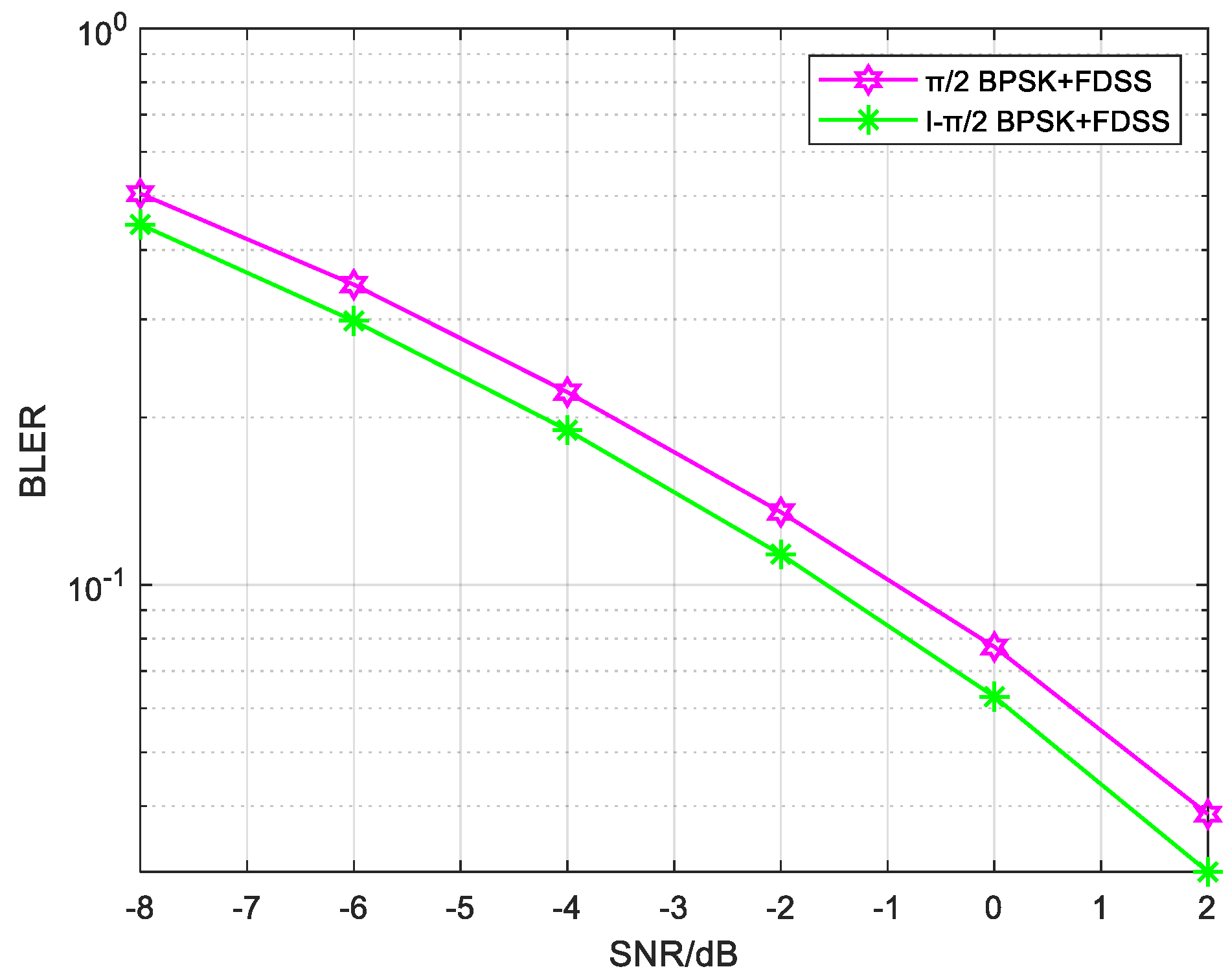
Then, the performance comparison between π/2-BPSK and I-π/2 BPSK with the addition of transparent FDSS (
α = 1) is provided. The wireless channel is TDL-A 10 Hz 100 ns, and the FDSS, which is transparent to the receiver, is also part of the channel. So, the channel asking for estimation is the combination of the wireless channel and FDSS. Other simulation parameters remain the same as in
Table 4. Real channel estimation is used in the simulation, and the pilot and data use the same modulation method.
The simulation results are shown in
Figure 15. It can be observed that with the addition of FDSS, I-π/2 BPSK outperforms π/2-BPSK in terms of BLER performance. Furthermore, according to the PAPR results shown in
Figure 8, I-π/2 BPSK with FDSS exhibits lower PAPR compared to π/2-BPSK. This highlights the advantage of using I-π/2 BPSK over π/2-BPSK when FDSS is employed; the performance improvement is approximately 0.6 dB at BLER = 0.1.
Based on the previous PAPR results, we can conclude that I-π/2 BPSK with FDSS has advantages over π/2 BPSK with FDSS in both PAPR and BLER, where the gains are approximately 1.4 dB and 0.6 dB, respectively.
5. Conclusions
The article proposes a new modulation scheme named ORIM, which is particularly suitable for low-power IoT applications and enhanced coverage scenarios in 6G systems. The principle of the ORIM scheme is introduced, which is based on interpolation modulation using QPSK, BPSK, and π/2 BPSK. ORIM demonstrates a significantly low PAPR, with all three ORIM variants exhibiting lower PAPR than π/2 BPSK and the trellis-coded QPSK. Furthermore, the article presents low complexity demodulation solutions for the three ORIM schemes based on the LLR algorithm. The simulation results show that, under the same data rate and spectral efficiency, compared with π/2 BPSK, ORIM achieves stable BLER performance without any performance loss, and is superior to trellis-coded QPSK. Additionally, when FDSS is applied, I-π/2 BPSK achieves better PAPR and BLER performance than π/2 BPSK under TDL-A channel conditions.
The simulation results of this paper are based on ideal channel estimation and the narrowband assumption. In our subsequent research, we will study the real channel estimation, scenarios with wider bandwidth, as well as methods for increasing spectral efficiency by adding spectral truncation, and also attempt to combine other methods for reducing PAPR for research.

