Abstract
The instantaneous AC-side output power of a two-stage single-phase inverter pulsates at twice the output voltage frequency, inducing second harmonic current (SHC) in the front-end DC–DC converter. While conventional SHC mitigation methods mainly focus on controller optimization for PWM-controlled DC–DC converters, LLC resonant converters, which have been widely adopted in two-stage single-phase inverters for high efficiency and soft-switching characteristics, lack tailored solutions due to frequency modulation complexities. To address this gap, this paper first analyzes the propagation mechanism of the SHC in terms of converter output impedance. Then, by simultaneously lowering the open-loop gain and increasing the output impedance of the DC–DC converter at 2fN, this paper proposes a hybrid SHC mitigation strategy that achieves low SHC and fast dynamic performance for frequency-modulated LLC converters. Finally, a 28 V DC to 220 V/50 Hz AC inverter was developed, and the experimental results verified the effectiveness of the proposed control strategy.
1. Introduction
As the aviation industry evolves toward More-Electric Aircraft (MEA) and All-Electric Aircraft (AEA), onboard power systems are increasingly adopting more efficient architectures such as variable-frequency AC (e.g., 230 VAC, 360–800 Hz) [1,2,3]. However, despite the high efficiency and power density this advanced system offers, specialized power sources tailored for avionics remain incompatible with standard ground equipment. Therefore, a critical need persists for efficiently and reliably converting conventional onboard 28 V DC power to standard 220 V/50 Hz AC to operate crucial medical devices, passenger electronics, and specialized instruments.
Addressing this challenge, two-stage single-phase inverter systems [4], which comprise a front-end DC–DC converter cascaded with a downstream DC–AC inverter, have emerged as prevalent solutions for integrating onboard 28 V DC with ground equipment. This configuration offers advantages in applications requiring wide-range DC input voltage regulation and scenarios involving a high voltage ratio between input sources and output requirements [5]. The front-end DC–DC converter regulates the variable DC input voltage into a stable intermediate DC bus voltage while providing galvanic isolation between input and output. The downstream DC–AC inverter then transforms this regulated DC voltage into the AC output, either to power electrical loads or synchronize with the utility by injecting controlled AC current.
The topology of the two-stage single-phase inverter is shown in Figure 1. The inherent double-frequency power fluctuation in single-phase AC systems creates an instantaneous power imbalance between the AC and DC sides [4,5]. This imbalance induces a double-frequency harmonic current in the front-end DC–DC converter, resulting in elevated switching device current stress, reduced conversion efficiency, and increased intermediate DC bus voltage ripple. Therefore, suppression of this second harmonic current (SHC) is critical to ensure system reliability and performance.

Figure 1.
Block diagram of a two-stage single-phase inverter.
Previous research has explored numerous methods to mitigate SHC in front-end DC–DC converters. The most straightforward approach involves enlarging the intermediate DC bus capacitance [6]. However, this method necessitates the use of bulky electrolytic capacitors, significantly compromising the converter power density. Moreover, an LC resonant circuit tuned at twice the fundamental frequency (2fN) can be paralleled with the DC bus [6], creating a low-impedance path to absorb SHC. However, the resonant circuit is sensitive to frequency or parameter deviations and reduces the system power density.
To achieve SHC attenuation while preserving power density, researchers have proposed active filtering methods without the utilization of bulky passive components. In [7,8,9,10], an active harmonic compensation circuit is shunt-connected to the intermediate DC bus to inject a phase-inverted SHC, matching the amplitude and frequency of the inherent ripple caused by the downstream DC–AC inverter, thereby canceling the ripple current and stabilizing the bus voltage. However, these approaches introduce trade-offs including increased system complexity, higher implementation costs, and additional switching losses that degrade overall efficiency.
Aiming for SHC suppression without ancillary hardware components, recent advancements have focused on advanced control methodologies for front-end DC–DC converters. These strategies employ dynamic impedance reshaping and adaptive feedforward compensation to attenuate harmonic propagation, while avoiding the need for additional filtering circuits through advanced modulation techniques and multi-loop control architectures. In [11], a high bandwidth inner current loop is inserted after the DC voltage loop of the front-end DC–DC converter to suppress the SHC. Although the SHC can be mitigated, the cutoff frequency of the DC voltage loop is reduced substantially to ensure proper decoupling between the voltage and current control loops. This bandwidth limitation, in turn, degrades the converter’s transient response. An inductor current feedforward strategy, which introduces a virtual resistor in series with the output inductor of the front-end DC–DC converter, is proposed in [12]. However, the virtual resistor elevates the converter output impedance across the whole frequency band, leading to dynamic performance degradation. By implementing a notch filter and PR controller in the voltage control loop [13], the converter output impedance can be reduced significantly at a selected frequency twice the fundamental frequency. However, its control performance is sensitive to the grid frequency, deteriorating rapidly once the frequency deviates. Reference [14] employs a notch filter integrated into the voltage control loop to attenuate the loop gain at twice the fundamental frequency. While effective in harmonic suppression, this approach introduces a significant phase lag, critically constraining the achievable voltage loop crossover frequency and thereby limiting system dynamic performance. Considering that high impedance is preferred only at two times the fundamental frequency, a series bandpass filter-based inductor current feedback control strategy is proposed in [15] to achieve SHC mitigation with enhanced system dynamic performance. In [16], by simultaneously introducing the intermediate bus voltage and inductor current feedback, two virtual impedances are introduced at the output of the DC–DC converter for increasing the converter’s double frequency impedance while decreasing impedance of other frequency bands, further improving the dynamic characteristics of the system. An active disturbance rejection controller based on a notch filter is proposed in [17] for boost converter front-ended two-stage inverters with the voltage loop bandwidth higher than 2fN. A similar impedance shaping-based SHC mitigation method is proposed for boost PFC converter front-ended PMSM drives [18].
However, existing SHC mitigation strategies predominantly target pulse-width modulation (PWM)-controlled front-end DC–DC converters. In contrast, frequency-modulated LLC resonant converters—favored for high voltage gain, high efficiency, high power density, and inherent soft-switching capabilities—have emerged as a prevalent front-end solution. Current active power decoupling methods primarily utilize PWM duty cycle adjustments to inject virtual impedance, enabling second-order power pulsation suppression. However, limited research addresses SHC mitigation in frequency-modulated LLC resonant converters, where variable switching frequency operation complicates impedance shaping and necessitates novel control paradigms to harmonize harmonic suppression with resonant tank dynamics. In [19], different SHC transfer characteristics of the LLC converter are analyzed, and a parameter design guideline to prevent SHC amplification during fixed-frequency operation is proposed. A voltage-oriented state plane feedforward-based second harmonic voltage ripple suppression method is proposed in [20] for an LLC converter front-ended two-stage rectifier. While this approach eliminates the need for state variable sensing, its efficacy critically depends on precise system modeling. A nonlinear feedforward-based strategy is proposed in [21] for SHC suppression in LLC converter front-ended two-stage rectifiers. While demonstrating effective harmonic attenuation, this method requires accurate system modeling and significant switching frequency variations to adapt to dynamic output current conditions, inducing system efficiency degradation.
To address these challenges, this work proposes a composite SHC mitigation strategy integrating notch filtering and virtual impedance synthesis for LLC converter front-ended single-phase inverters. Unlike existing PWM and PFM-based SHC suppression methods requiring multi-sensor implementations or suffering from wide frequency deviations, the proposed approach achieves comparable harmonic attenuation using only one additional current sensor while maintaining low switching frequency variations. In addition, considering that the converter’s fundamental frequency only relies on the inverter control strategy, the performance of the proposed virtual impedance and the notch filter-based SHC strategy is robust against system parameter variations. By utilizing the downstream inverters’ inherent voltage stabilization capability, the frequency modulation range of the front-end DC–DC converter can be further constrained, enhancing the system efficiency. Section 2 initially elaborates on SHC propagation characteristics under open-loop and closed-loop control of the LLC converter. Section 3 investigates the proposed hybrid SHC mitigation strategy, while Section 4 shows the controller design method and impedance analysis. Experimental results are analyzed and discussed in Section 5. Finally, conclusions are presented in Section 6.
2. SHC Propagation Characteristic Analysis Based on SLLC Converters
Conventional LLC resonant converters are widely adopted for high-efficiency applications due to their inherent soft-switching capabilities, enabling zero-voltage switching (ZVS) of primary-side transistors and zero-current switching (ZCS) of secondary rectifiers across full-load conditions [22]. However, in applications such as the 28 V DC to 220 V/50 Hz AC single-phase inverter investigated in this work, which requires an 8:1 voltage boost ratio and high input currents, the conventional LLC topology faces a significant limitation due to large resonant tank losses. To address this, a secondary-side resonant LLC topology (SLLC) [23] is implemented as the front-end DC–DC stage. By relocating the resonant network to the transformer’s secondary side, circulating currents in the resonant tank are minimized, reducing conduction losses compared to primary-resonant LLC configurations. As illustrated in Figure 2, the two-stage architecture comprises the SLLC converter and a downstream inverter. Note that a single-phase full-bridge topology is adopted for the DC–AC converter, which is regulated by a dual-loop voltage/current controller and bipolar SPWM modulation strategy. For the purpose of SHC analysis, this paper models the inverter as a parallel connection of an ideal DC current source and an SHC source. This approach is justified since this paper mainly focuses on the suppression of the second harmonic current.

Figure 2.
Topology of SLLC converter front-ended two-stage single-phase inverter.
Due to the double-frequency (2fN) pulsating power of the inverter, the SHC from the DC–AC stage is inherently shared between the front-end DC–DC converter and the intermediate DC bus capacitor in two-stage single-phase inverters, as depicted in Figure 2. This SHC propagation originates from the impedance characteristics of the current flow path, where the converter output impedance Zo(s) and bus capacitor admittance YCbus(s) jointly govern harmonic current distribution at 2fN.
The SLLC resonant converter regulates output voltage by modulating its switching frequency to adjust the voltage gain of the resonant tank. Unlike pulse-width modulation (PWM)-based counterparts, its small-signal modeling is inherently complex due to the nonlinear dynamics of resonant operation. To address this, the extended describing function (EDF) method [24] is applied under the fundamental harmonic approximation (FHA) framework, enabling the derivation of frequency-domain transfer characteristics. When operating in below resonant or resonant frequency modes (fsw ≤ fr), the SLLC converter achieves high conversion efficiency by realizing ZVS across primary devices, and the corresponding equivalent small-signal circuit is illustrated in Figure 3. In the figure, iinv denotes the current of the downstream DC–AC inverter stage, Cbus denotes the capacitor of the intermediate DC bus, , , are the disturbance of the input voltage, switching frequency, and output voltage, respectively. Zo(s) and Zo1(s) are the open-loop output impedance of the SLLC converter with and without Cbus, respectively. Kv and Kd are the coefficients of the controlled voltage source, and can be expressed as follows:
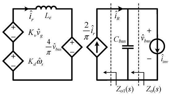
Figure 3.
Equivalent small signal model of the SLLC converter.
Based on the derived small signal model, the system control block diagram can be obtained to facilitate stability analysis and controller design for robust voltage regulation under wide input variations. Considering that the system input voltage is stable, is approximately 0. Then, the open-loop and closed-loop control block diagrams of the system can be obtained and are depicted in Figure 4 and Figure 5, respectively.

Figure 4.
Open-loop control block diagram of the SLLC converter.

Figure 5.
Closed-loop control block diagram of the SLLC converter.
Consequently, the system transfer function from output voltage to switching frequency can be derived as (3). Note that the derivation with a switching frequency smaller than the resonance frequency is illustrated for the sake of simplicity. As can be seen from Figure 6, the derived model aligns well with that in the simulation, validating the small-signal approximation accuracy. Consequently, the voltage loop PI controller can be designed by setting the bandwidth and phase margin to 450 Hz and 45°, respectively. Note that the parameters of the converter are listed in Table 1.
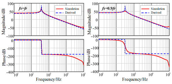
Figure 6.
Bode plot of the system.

Table 1.
Parameters of the converter.
After designing the converter parameters, this paper employs an impedance-based analytical framework to quantify SHC propagation dynamics in the two-stage inverter. The methodology focuses on frequency-dependent interactions through admittance ratio analysis. According to Figure 4, the open-loop output impedance of the SLLC converter can be derived as follows:
where ωs denotes the switching frequency, ωr denotes the resonance frequency, and Le denotes the equivalent inductance. Assuming Cbus is small enough and all the SHC is provided by the SLLC converter, then the SLLC converter open-loop output impedance without the output capacitor can be derived as follows:
In order to analyze the SHC flow path under open-loop state, the corresponding equivalent circuit of the SLLC converter is drawn in Figure 7. As can be seen, the SHC from the downstream DC–AC converter is supplied by both the converter and the intermediate bus capacitor, and the SHC division ratio is governed by the frequency-dependent impedance magnitudes at 2fN.
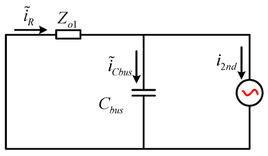
Figure 7.
Equivalent circuit of SHC flow path under open-loop state.
Then, the SHC of the SLLC converter output current under open-loop control can be derived as follows:
where i2nd is the SHC required by the load, and iCbus is the capacitor current. Note that Le remains constant, since the open-loop SLLC converter operates at a fixed switching frequency. Under these conditions, (7) reveals that the amplitude of the SHC provided by the SLLC converter is inversely proportional to the intermediate bus capacitance.
By shifting the comparison point in the closed-loop control block diagram shown in Figure 5, the equivalent control block diagram is obtained as depicted in Figure 8. Based on the figure, the SHC flow path of the SLLC converter under feedback control can be modeled, and the corresponding equivalent circuit is depicted in Figure 9. As can be seen, the controller introduces a virtual impedance Zvs(s) in parallel with the open-loop output impedance Zo1(s). Note Zvs(s) can be derived as follows:

Figure 8.
Closed-loop control block diagram of SLLC converter.
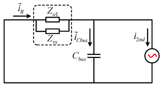
Figure 9.
Equivalent circuit of SHC flow path under closed-loop state.
Meanwhile, the SHC of the SLLC converter output current under closed-loop control can be derived as follows:
where iR_cl is the SHC provided by the converter under closed-loop state.
Assuming a proportional–integral (PI) controller is utilized in the voltage control loop, then Zvs(s) can be further derived as follows:
where kpv and kiv are the proportional and integral coefficients of the voltage controller, respectively. From (10), it can be seen that Zvs(s) is the parallel connection of Zvs1(s) and Zvs2(s). Note that Zvs1(s) can be seen as a negative resistor due to its constant −180° phase angle, while Zvs2(s) behaves like an inductor at 2fN. The existence of both impedances contributes to lowering the SLLC converter output impedance, and as kpv/kiv increases, the output impedance can be further decreased. Consequently, increased SHC conductance through the front-end SLLC converter via the resonant tank, H-bridge, and DC input capacitor, as illustrated in Figure 10. This unintended redistribution introduces higher switching and passive component losses, revealing a compromise in intermediate bus voltage regulation: the voltage regulation capability of the controller inherently conflicts with the SHC mitigation performance.

Figure 10.
The SHC flow path.
3. Proposed SHC Mitigation Strategy
3.1. Principle of the SHC Mitigation Strategy
According to Figure 5, the transfer function from the converter switching frequency to the output voltage, and the corresponding voltage loop gain T(s) are derived as follows:
Then, the closed-loop output impedance of the SLLC converter can be derived as follows:
By substituting (5), (11), and (12) into (13), and assuming Cbus is sufficiently small to be neglected, most of the SHC flows into the front-end converter. Under these circumstances, the closed-loop output impedance of the SLLC converter without Cbus can be derived as follows:
Effective suppression of the SHC within the front-end SLLC converter necessitates enlarging the amplitude of Zo1_CL(s) at twice the fundamental frequency. As derived in (14), two distinct strategies enable this increase:
(1) Lowering the amplitude of the system open-loop gain at 2fN.
(2) Increasing the amplitude of the open-loop output impedance Zo1_CL(s) at 2fN.
It is important to note that increasing Zo1_CL(s) through the first method has a limit: the maximum value of Zo1_CL(s) that can be reached is Zo1(s), which occurs when the amplitude of Gv(s) at 2fN becomes zero. Moreover, to effectively absorb SHC and limit voltage ripple at the intermediate DC bus, Cbus must be sized based on the double-frequency power pulsation, and the minimum capacitance can be derived as follows:
where Po is the output power, Vbus is the intermediate bus voltage, and ΔVbus is the maximum allowable voltage ripple.
3.2. Hybrid SHC Mitigation Strategy
Based on the two suppression principles established in the previous section, this paper proposes a hybrid SHC mitigation strategy for two-stage single-phase inverters. This approach can simultaneously attenuate the voltage loop gain at 2fN through notch filter integration and amplify open-loop output impedance at 2fN via virtual impedance synthesis. This coordinated action achieves SHC reduction while maintaining voltage loop bandwidth to overcome the compromise between harmonic suppression and dynamic performance degradation observed in conventional methods.
3.2.1. Notch Filter-Based SHC Mitigation Strategy
To attenuate the open-loop gain at 2fN, a notch filter-based SHC mitigation strategy (NFS), where the filter GN(s) centered at 2fN is cascaded within the voltage loop regulator Gv(s), is proposed. The control block diagram is shown in Figure 11, and the expression of GN(s) is given as follows:

Figure 11.
Block diagram of NF-based SHC mitigation strategy.
The frequency-selective attenuation mechanism elevates the output impedance characteristic of the SLLC converter at 2fN, thereby redirecting SHC circulation to the DC bus capacitor rather than through power semiconductor components. Significantly, the control architecture maintains the converter loop gain across non-targeted frequencies, ensuring enhanced harmonic impedance shaping for SHC mitigation and preservation of transient response dynamics. The proposed notch filter-based strategy demonstrates placement flexibility, achieving equivalent SHC suppression when implemented in the voltage feedback loop configuration, as shown in Figure 11. Note that to ensure system stability when implementing the NFS strategy, the output of the notch filter is cascaded with a unity-gain low-pass filter.
After inserting a filter into the voltage control loop, the closed-loop output impedance of the SLLC converter can be derived as follows:
3.2.2. Virtual Impedance-Based SHC Mitigation Strategy
As can be seen from (17), the NFS control strategy has a limited influence on the SLLC converter’s closed-loop output impedance. Accordingly, following the SHC suppression principle listed in the previous section, a series of virtual impedance Zs(s) is introduced at the output of the diode rectifier bridge, thereby significantly increasing the closed-loop output impedance of the SLLC converter, as shown in Figure 12.
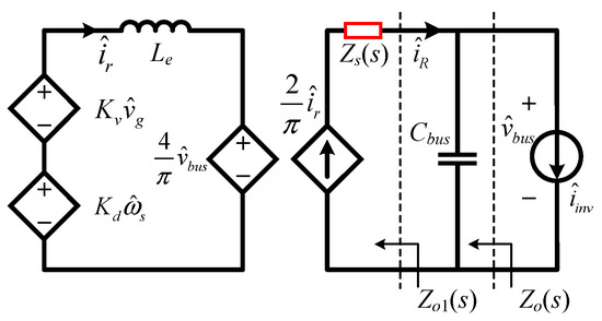
Figure 12.
The small signal model with the virtual impedance implemented.
The virtual impedance Zs(s) must exhibit frequency-selective characteristics to balance impedance enhancement and dynamic performance preservation. Specifically, Zs(s) should be designed to present high impedance exclusively at 2fN for harmonic suppression, while maintaining near-zero impedance across all other frequencies. This targeted impedance profile prevents broad-spectrum output impedance amplification that would otherwise degrade the converter’s transient response and voltage regulation bandwidth. The required amplitude–frequency response of Zs(s), featuring a sharp resonance peak at 2fN, is rigorously defined in Figure 13.
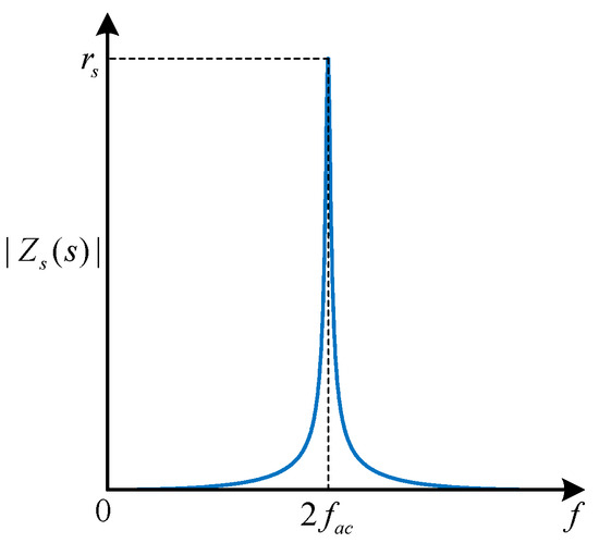
Figure 13.
Amplitude of the virtual impedance.
According to Figure 13, the basic form of the virtual impedance Zs(s) is as follows:
where rs is the impedance amplitude of Zs(s) at 2fN, GBPF(s) is the transfer function of the bandpass filter (BPF) centered at 2fN with the following expression.
where ωb = 2πfb is the BPF bandwidth, ω0 = 2πf0 is the BPF center frequency. Note that the gain of the BPF is 1 at 2fN. To ensure sufficient coverage of voltage frequency variations, fb must maintain a minimum threshold. Conversely, excessive bandwidth expansion would introduce undesirable impedance amplification in out-of-band frequency ranges. Through systematic analysis of these competing requirements, an optimal bandwidth of fb = 10 Hz has been determined in this paper, achieving effective frequency selectivity while maintaining satisfactory out-of-band rejection characteristics.
Based on the aforementioned analysis, virtual impedance can be achieved through feedback control of the SHC, which is extracted from the rectifier bridge output current using the BPF. This configuration leads to the modified SLLC converter control architecture, as shown in Figure 14. Then, the equivalent output impedance of the converter can be expressed as follows:
where ZR(s) is the output impedance with VI implemented.

Figure 14.
Control block diagram with virtual impedance.
As can be seen from (20), the output impedance of the SLLC converter at 2fN can be adjusted by tuning rs.
To implement a series virtual impedance within the control system, the feedback point for the rectifier bridge current shown in Figure 14 can be moved forward to either the output or input of the voltage controller. The former method effectively superimposes a double-frequency component onto the switching frequency via the feedback branch. The latter, however, superimposes a double-frequency voltage component onto the reference voltage through its feedback branch. While their working principles are identical, the design of the transfer function and control parameters on their respective feedback branches differs. Control block diagrams of the two methods are shown in Figure 15 and Figure 16, respectively. Note that transfer functions of the feedback are shown in Equations (21) and (22), respectively.

Figure 15.
Control block diagram with the feedback point at the controller output.

Figure 16.
Control block diagram with the feedback point at the controller input.
After adopting the control strategy of series virtual impedance of the rectifier bridge branch, the closed-loop output impedance of the SLLC converter that does not include Cbus is as follows:
The closed-loop output impedance of the SLLC converter, excluding Cbus, can be expressed as follows after implementing the series virtual impedance control strategy:
3.2.3. The Proposed Hybrid SHC Mitigation Method
To achieve a superior SHC suppression effect, this paper proposes to simultaneously implement the NFS and VI-based SHC mitigation strategy. This hybrid method can increase the open-loop output impedance of the SLLC converter at 2fN while reducing the voltage loop gain at the same frequency, and consequently, further amplifies the SLLC converter’s closed-loop output impedance at 2fN. The control block diagram of the SLLC converter under this hybrid control scheme is shown in Figure 17, and its closed-loop output impedance is derived in (24).
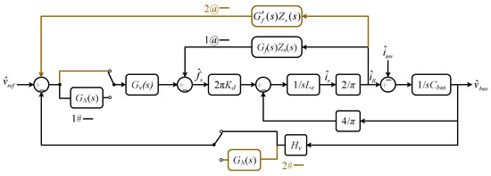
Figure 17.
Control block diagram of the hybrid SHC mitigation method.
4. Parameters Design and Performance Analysis
4.1. Closed-Loop Parameter Design
According to Mason’s theorem, the open-loop gain of the system with virtual impedance shown in Figure 15 can be derived as follows:
As Figure 18 illustrates, the system’s open-loop gain exhibits two resonant spikes and sharp phase jumps in its amplitude and frequency curve, due to the influence of GBPF(s). These characteristics can potentially lead to system instability, and to suppress these resonant spikes, a damping resistor, rd, can be added in series with the introduced VI rsGBPF(s). This modification smooths the phase-frequency curve of the loop gain, thereby increasing the system stability margin. Based on a trial-and-error approach, rd is set to 0.1rs to effectively suppress the resonant peak with minimal impact on SHC mitigation performance.
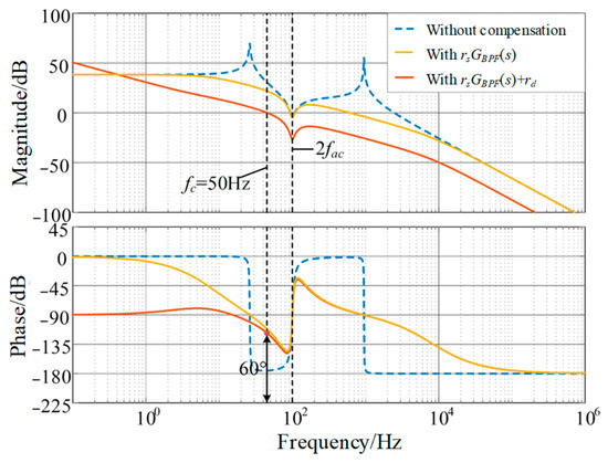
Figure 18.
System loop gain w/wo the SHC mitigation methods.
By replacing rsGBPF(s) with rsGBPF(s) + rd in (25), the system loop gain with a damping resistor can be derived as follows:
The yellow line shown in Figure 18 is the loop gain Bode plot after damping. It can be seen that the resonant peak is effectively suppressed, and the severity of system phase changes is reduced, significantly enhancing stability margins.
Normally, a PI controller is utilized as the voltage regulator with the following expression:
where the crossover frequency fL is as follows:
To enhance SHC mitigation performance, the system cutoff frequency is set below 2fN. This prevents interaction with the filter introduced by the NFS strategy, which is centered at 2fN. When fL of the PI controller is significantly smaller than the system cutoff frequency, the voltage controller can be simplified to a proportional controller, Kp. Then, by the definition of cutoff frequency, the system loop gain is as follows:
Based on (28) and (29), Kp and Ki can be derived as follows:
Note that fL is 5 Hz in the paper.
Moreover, to analyze the SHC magnitude entering the front-end DC–DC converter following the implementation of the proposed controller, the transfer function relating the DC–AC converter input current to the DC–DC converter rectifier output current is derived as follows:
Then, αSHC, which stands for the percentage of the SHC contained in the rectifier bridge of the SLLC converter, can be obtained as follows:
With αSHC = 0.05, and by incorporating the data from Table 1 into (32), the magnitude of the VI can be derived as follows:
According to (33), if the SHC flowing into the SLLC converter is confined within 5%, the value of rs should be larger than 368.5 Ω. However, since the actual BPF is non-ideal, increasing rs will also elevate the output impedance of the SLLC converter in frequency bands other than 2fN, thereby affecting the converter’s dynamic performance. Consequently, rs cannot be too large and is set to 400 Ω in the paper. After designing the VI, parameters of the voltage loop controller can then be obtained utilizing (30) and (31), respectively.
4.2. SLLC Converter Output Impedance Comparison Under Different Control Strategies
The closed-loop output impedance of the SLLC converter under different control strategies is shown in Figure 19. Note that the solid black line indicates the impedance of the intermediate bus capacitor. The following can be observed from Figure 19:
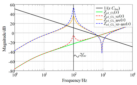
Figure 19.
Output impedance amplitude of the SLLC converter under different control strategies.
- When the SLLC converter operates under closed-loop control without an SHC suppression strategy, its closed-loop output impedance, Zo1_CL(s), is much smaller than the impedance of the intermediate bus capacitor at 2fN. This leads to a significant amount of SHC flowing into the SLLC converter.
- When adopting the NFS control strategy, the integrated notch filter ensures that the closed-loop voltage control does not significantly reduce the output impedance at 2fN. Consequently, the amplitude of the SLLC converter closed-loop output impedance, Zo1_CL_NF(s), at 2fN is notably increased, leading to a reduction in the second harmonic current content within the converter.
- Implementation of the VI-based SHC mitigation strategy introduces a series-connected virtual impedance within the rectifier bridge, selectively increasing the SLLC converter output impedance at 2fN. Consequently, the magnitude of the output impedance Zo1_CL_BPF(s) rises significantly, reducing SHC penetration into the SLLC converter.
- Implementation of both the NF- and VI-based control strategy—cascading a notch filter in the voltage loop and inserting virtual impedance in series with the rectifier bridge—maximizes the magnitude of the SLLC converter output impedance Zo1_CL_NF+BPF(s) at 2fN. This selective impedance peaking achieves optimal SHC suppression.
5. Experimental Verification
To validate the proposed control strategy, a two-stage DC–AC converter prototype was developed in this paper. Key parameters are detailed in Table 1, with the physical implementation shown in Figure 20. Note that the parameters design strategy of the DC–AC converter has been well-established in previous studies [25,26]; this paper presents only the designed parameter values. To analyze the SHC mitigation performance, this section presents experimental results for the proposed NF, VI, and NF+VI control strategies with a detailed comparison.
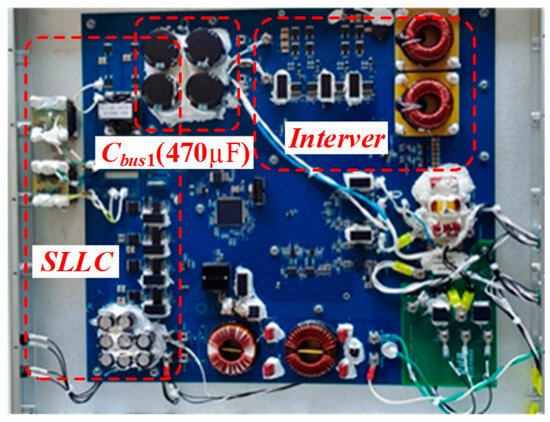
Figure 20.
The two-stage DC–AC inverter prototype.
The open- and closed-loop converter input current, resonant inductor current, intermediate bus voltage, output voltage, and output current waveforms are shown in Figure 21 and Figure 22, respectively. As can be seen, the closed-loop implementation increases the SHC amplitude in the input current from 30% to 70% based on FFT analysis, attributed to a significant reduction in the SLLC converter output impedance under closed-loop control. While achieving bus voltage stabilization within required fluctuation ranges, this amplified SHC propagation reveals the limitation of solely relying on front-end converter closed-loop regulation, as the resultant harmonic deterioration compromises system efficiency and reliability, necessitating complementary harmonic suppression strategies for balanced voltage and power quality performance.
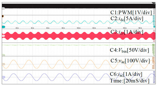
Figure 21.
Waveforms when the SLLC converter operates under open-loop state.
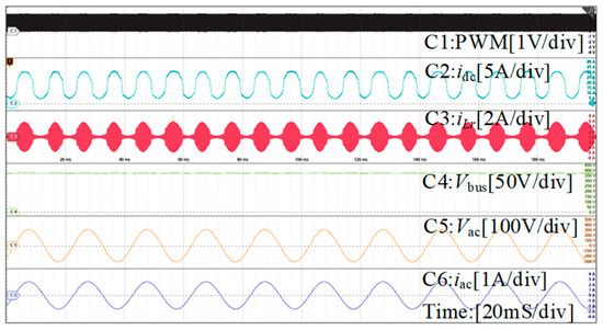
Figure 22.
Waveforms when the SLLC converter operates under closed-loop state.
Figure 23 indicates that after implementing the NF-based SHC mitigation strategy, the SHC amplitude is significantly reduced, and the SHC content in idc is about 37%, slightly higher than that of the open-loop state, but substantially lower than the 70% SHC content measured under conventional closed-loop control. These results show the correctness of the theoretical analysis regarding system impedance characteristics. Notably, while the NFS strategy successfully mitigates the SHC induced by closed-loop feedback control, its inherent limitation prevents additional impedance injection at 2fN. The SHC content increase compared to that of the open-loop system stems from this restricted impedance compensation capability, illustrating the practical constraints of the NFS strategy for SHC suppression.
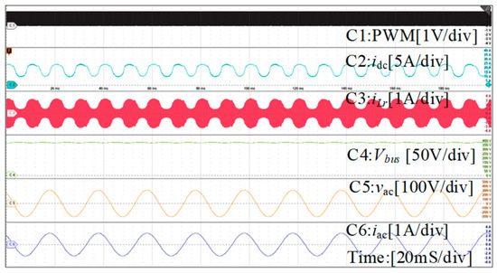
Figure 23.
Steady-state experimental waveform under NF-based control strategy.
Figure 24 presents the inverter steady-state waveforms under the VI-based control strategy, while Figure 25 illustrates the FFT analysis of the converter input current. As can be seen, the SHC content in idc reduces to about 5.2%, which demonstrates that connecting virtual impedance in series with the converter effectively increases the SLLC converter closed-loop output impedance amplitude at 2fN, thereby suppressing the SHC of the input current. Although the SHC content is slightly higher than the designed αSHC (5%), it can validate the effectiveness of the proposed impedance-based analysis. This mitigation mismatch is brought about by the digital delay of the controller and parasitic parameters of the SLLC converter.
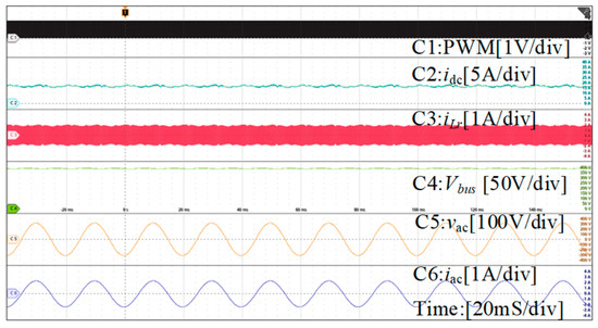
Figure 24.
Steady-state experimental waveform under VI-based control strategy.
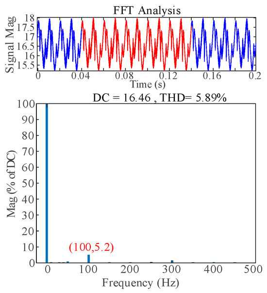
Figure 25.
THD of idc under VI-based control strategy.
To further enhance SHC mitigation performance, the NF and VI-based hybrid strategy is implemented simultaneously. Figure 26 and Figure 27 show the corresponding steady-state waveforms of the inverter. As can be seen from the figures, the converter input current pulsation is barely visible, and the SHC content in idc significantly reduces to approximately 1.75%. This enhanced performance demonstrates that the combination of reducing the voltage loop gain and increasing the SLLC converter output impedance maximizes the closed-loop output impedance magnitude at the selected frequency 2fN, thereby achieving optimal SHC mitigation performance. These experimental results align closely with the impedance-based analysis presented in Figure 19. Then, αSHC under different control strategies is listed in Table 2 to show the performance of the proposed SHC mitigation strategy.
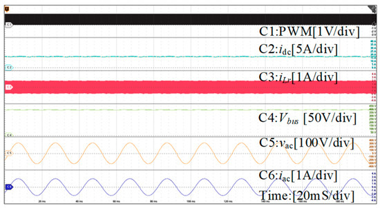
Figure 26.
Steady-state experimental waveform under the hybrid control strategy.
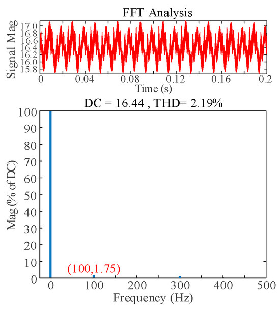
Figure 27.
THD of idc under the hybrid control strategy.

Table 2.
Comparison of the SHC content under different control strategies.
To validate the controller performance against AC frequency variations, experiments were conducted by changing the inverter reference frequency to 49.5 Hz. As shown in Figure 28, a slight degradation in mitigation performance is observed, with the input current THD increasing from 2.18% to 2.52%. The slight performance degradation is attributed to the gain reduction in the NF and BPF at off-nominal frequencies. A trade-off exists where increasing the filter bandwidth improves frequency adaptation at the expense of peak mitigation performance. However, these results still validate the robustness of the controller against AC frequency deviations.
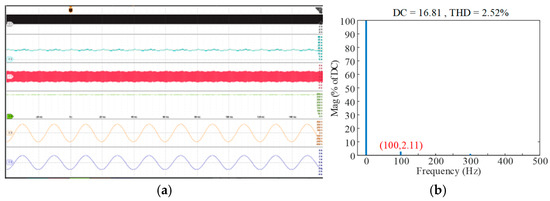
Figure 28.
SHC mitigation results under frequency variations. (a) waveforms, (b) THD.
To verify the converter’s dynamic performance under the proposed hybrid control strategies, experiments were conducted during load transients. Figure 29 shows waveforms during load step changes, specifically from full load to half load and back from half load to full load. As shown, both the DC-link current (idc) and the intermediate bus voltage ripple (ΔVbus) exhibit minimal overshoot and undershoot, settling rapidly to the new steady state. This confirms the excellent dynamic characteristics of the system under the proposed control strategy. Moreover, the input current THD at half load was calculated and is presented in Figure 30. The results show that the THD is comparable to that under full-load conditions, confirming the effectiveness of the proposed control strategy across various operational states.
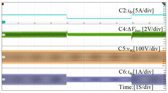
Figure 29.
System waveforms during a load step transient with the hybrid control strategy.
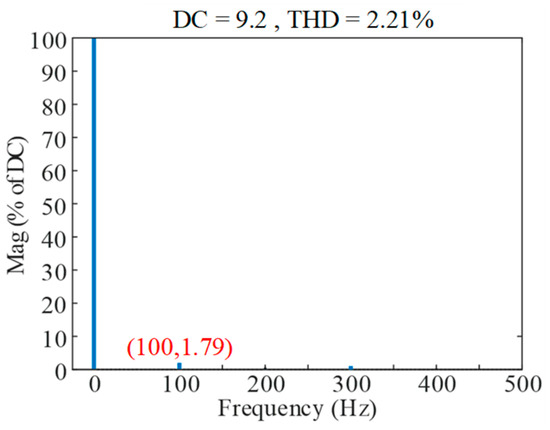
Figure 30.
THD of idc under half-load condition.
6. Conclusions
This paper investigated a two-stage single-phase inverter with an SLLC resonant converter as its front-end stage. To address the prevalent SHC problem, the paper first analyzed its generation mechanism and propagation path. Building upon this, the paper proposes a hybrid SHC mitigation strategy for the DC side. The proposed strategy integrates a notch filter in the voltage loop along with a series virtual impedance implemented at the output of the SLLC converter. Experimental results demonstrate that the proposed control strategy mitigates the SHC content to 1.75% while simultaneously ensuring robust dynamic characteristics for the system.
Author Contributions
Conceptualization, X.Z.; methodology, X.Z.; software, P.C.; validation, P.C.; formal analysis, K.M.; investigation, P.C.; resources, X.W. (Xuanlyu Wu) and X.W. (Xiaohua Wu); data curation, X.C.; writing—original draft preparation, P.C.; writing—review and editing, X.Z. and X.W. (Xuanlyu Wu); visualization, X.L.; supervision, X.Z.; project administration, X.W. (Xiaohua Wu); funding acquisition, X.Z. All authors have read and agreed to the published version of the manuscript.
Funding
This research was supported by the National Natural Science Foundation of China, grant number 52107208.
Data Availability Statement
Data are contained within the article.
Conflicts of Interest
The authors declare no conflicts of interest.
References
- Buticchi, G.; Wheeler, P.; Boroyevich, D. The More-Electric Aircraft and Beyond. Proc. IEEE 2023, 111, 356–370. [Google Scholar] [CrossRef]
- Barzkar, A.; Ghassemi, M. Components of Electrical Power Systems in More and All-Electric Aircraft: A Review. IEEE Trans. Transp. Electrif. 2022, 8, 4037–4053. [Google Scholar] [CrossRef]
- Liang, Y.; Bodnár, D.; Ram Chandra Mouli, G.; Ragni, D.; Bauer, P. Charging Demand Prediction: Small All-Electric Aircraft and Electric Vertical Takeoff and Landing Aircraft. IEEE Trans. Transp. Electrif. 2025, 11, 2732–2747. [Google Scholar] [CrossRef]
- Cervone, A.; Darvishzadeh, A.; Dujic, D. Active Filtering of Second-Order Harmonic in Two-Stage Single-Phase AC/DC Converters with Frequency Modulated Series-Resonant Converters. IEEE Trans. Power Electron. 2025, 40, 14908–14922. [Google Scholar] [CrossRef]
- Zarkab Farooqi, M.; Singh, B.; Panighiri, B. Performance Enhancement of Single-Phase Two-Stage AC-DC Converter with Reduced DC-Link Capacitance. IEEE Trans. Ind. Appl. 2023, 59, 5739–5748. [Google Scholar] [CrossRef]
- Das, J. Passive filters—Potentialities and limitations. IEEE Trans. Ind. Appl. 2004, 40, 232–241. [Google Scholar] [CrossRef]
- Kan, S.; Ruan, X.; Li, X. Topology and control for second harmonic current reduction in two-stage single-phase inverter without electrolytic capacitors. IEEE Trans. Power Electron. 2024, 39, 9051–9058. [Google Scholar] [CrossRef]
- Zhang, Y.; Fang, J.; Gao, F.; Song, T.; Gao, S.; Rogers, D.J. Second-harmonic ripple voltage suppression of integrated single-phase pulse width modulation rectifier charging system for EVs. IEEE Trans. Power Electron. 2020, 35, 3616–3626. [Google Scholar] [CrossRef]
- Wu, H.; Wong, S.; Tse, C.K.; Chen, Q. Control and modulation of bidirectional single-phase AC–DC three-phase-leg SPWM converters with active power decoupling and minimal storage capacitance. IEEE Trans. Power Electron. 2016, 31, 4226–4240. [Google Scholar] [CrossRef]
- Huang, X.; Ruan, X.; Fang, J.; Kan, S. A virtual impedance based control scheme for modular electrolytic capacitor-less second harmonic current compensator. IEEE Trans. Ind. Electron. 2021, 68, 198–209. [Google Scholar] [CrossRef]
- Liu, C.; Lai, J.S. Low frequency current ripple reduction technique with active control in a fuel cell power system with inverter load. IEEE Trans. Power Electron. 2007, 22, 1429–1436. [Google Scholar] [CrossRef]
- Zhang, L.; Ren, X.; Ruan, X. Control strategy for suppressing second harmonic current in two-stage inverter based on virtual impedance and increasing system bandwidth. Trans. China Electrotech. Soc. 2014, 29, 136–144. [Google Scholar]
- Jung, H.J.; Ha, K.S.; Song, B.M.; Lai, J.S.; Hyun, D.S.; Kim, R.Y. Low frequency current reduction using a quasi-notch filter operated in two-stage DC-DC-AC grid-connected systems. In Proceedings of the 2011 IEEE Energy Conversion Congress and Exposition, Phoenix, AZ, USA, 17–22 September 2011; pp. 2746–2750. [Google Scholar]
- Wei, Z.; Deng, X.; Gong, C.; Chen, J.; Zhang, F. A novel technique of low frequency input current ripple reduction in two-stage DC-AC inverter. In Proceedings of the IECON 2012—38th Annual Conference on IEEE Industrial Electronics Society, Montreal, QC, Canada, 25–28 October 2012; pp. 139–143. [Google Scholar]
- Zhang, L.; Ren, X.; Ruan, X. A Bandpass Filter Incorporated Into the Inductor Current Feedback Path for Improving Dynamic Performance of the Front-End DC–DC Converter in Two-Stage Inverter. IEEE Trans. Ind. Electron. 2014, 61, 2316–2325. [Google Scholar] [CrossRef]
- Zhang, L.; Ruan, X.; Ren, X. Second-Harmonic Current Reduction and Dynamic Performance Improvement in the Two-Stage Inverters: An Output Impedance Perspective. IEEE Trans. Ind. Electron. 2015, 62, 394–404. [Google Scholar] [CrossRef]
- Zhang, D.; Zhang, Y.; Wang, X. Impedance model-based dual-loop control strategy for a two-stage inverter with second harmonic current reduction and dynamic performance improvement. IEEE Trans. Ind. Electron. 2025. early access. [Google Scholar]
- Qu, D.; Li, B.; Wang, G.; Wang, S.; Wang, Q.; Zhang, G. Virtual admittance reshaping based ripple current suppression strategy of DC-Link capacitors for PMSM drives. IEEE Trans. Power Electron. 2025, 40, 16443–16455. [Google Scholar] [CrossRef]
- Wei, T.; Cervone, A.; Dujic, D. second harmonic induced resonant modes of fixed-frequency operated LLC converters. IEEE Trans. Ind. Appl. 2025, 61, 6547–6555. [Google Scholar] [CrossRef]
- Chen, J.; Xu, J.; Tang, H.; Bi, Y.; Peng, Y.; Wang, Y. Second harmonic voltage suppression for LLC converter in dual-stage single-phase rectifier based on voltage-oriented state plane feedforward control. IEEE Trans. Power Electron. Lett. 2023, 38, 9329–9334. [Google Scholar] [CrossRef]
- Wu, C.; Chen, J.; Chen, X.; Wang, Y. Second harmonic current reduction for two-stage single-phase rectifier with LLC converter based on charge control with nonlinear feedforward. IEEE Trans. Power Electron. 2024, 39, 15409–15413. [Google Scholar] [CrossRef]
- Xu, H.; Yin, Z.; Zhao, Y.; Huang, Y. Accurate Design of High-Efficiency LLC Resonant Converter with Wide Output Voltage. IEEE Access 2017, 5, 526653–526665. [Google Scholar] [CrossRef]
- Kim, E.; Chung, B.; Kang, S.; Cha, I.; Kye, M. A Novel Topology of Secondary LLC Series Resonant Converter. In Proceedings of the 22nd IEEE Applied Power Electronics Conference and Exposition, Anaheim, CA, USA, 25 February–1 March 2007; pp. 1625–1629. [Google Scholar]
- Corti, F.; Bertolini, V.; Reatti, A.; Faba, A.; Cardelli, E. Advanced Modeling Approach for LLC Resonant Converters: From Multiharmonic Analysis to Small Signal Model. IEEE Trans. Power Electron. 2025, 40, 3899–3915. [Google Scholar] [CrossRef]
- Zmood, D.; Holmes, D. Stationary frame current regulation of PWM inverters with zero steady-state error. IEEE Trans. Power Electron. 2003, 18, 814–822. [Google Scholar] [CrossRef]
- Mohiuddin, S.; Du, W.; Lyu, X.; Kim, J.; Nguyen, Q. A two-stage current limiting control strategy for direct-droop-controlled grid-forming inverters. IEEE Trans. Ind. Appl. 2025, 61, 6472–6483. [Google Scholar] [CrossRef]
Disclaimer/Publisher’s Note: The statements, opinions and data contained in all publications are solely those of the individual author(s) and contributor(s) and not of MDPI and/or the editor(s). MDPI and/or the editor(s) disclaim responsibility for any injury to people or property resulting from any ideas, methods, instructions or products referred to in the content. |
© 2025 by the authors. Licensee MDPI, Basel, Switzerland. This article is an open access article distributed under the terms and conditions of the Creative Commons Attribution (CC BY) license (https://creativecommons.org/licenses/by/4.0/).