Abstract
This work proposes a methodology for the automated sizing of transistors in analog integrated circuits, based on a modular and hierarchical representation of the circuit. The methodology combines structured design techniques and systematic design flow to generate a hierarchy of simplified macromodels that define their specifications locally and are interconnected with other macromodels or transistor-level primitive blocks. These primitive blocks can be described using symbolic models or pre-characterized data from look-up tables (LUTs). The symbolic representation of the system is obtained using Modified Nodal Analysis (MNA), and the exploration of each block is performed using local design spaces constrained by top-level specifications. The methodology is validated through the design of low dropout voltage regulators (LDOs) for DC-DC integrated power systems using open-source tools and three process design kits: Sky130A, GF180MCU, and IHP-SG13G2. Results show that the methodology allows the exploration of several topologies and technologies, demonstrating its versatility and modularity, which are key aspects in analog design.
1. Introduction
The design of analog integrated circuits (ICs) faces numerous challenges in the technology landscape, which demands increasingly efficient and robust solutions, particularly in terms of power consumption, area usage, and tolerance to process variability [1]. These circuits are essential for linking the physical and digital worlds, enabling signal conditioning and data conversion for electronic systems [2]. Despite their importance, analog IC design remains constrained by the lack of abstraction and standardized tools that can simplify the design process and promote a repeatable and systematic design flow [3,4]. As a result, analog design is often considered a bottleneck in integrated system development and a major barrier to improving the productivity of design teams [5,6].
The increasing demand for more efficient and portable analog integrated circuits has further exposed the limitations of traditional design flows, which are highly dependent on designer expertise and iterative manual tuning. Unlike digital design, analog design automation remains a significant challenge because of the high sensitivity of circuit behavior to process variations and its inherent nonlinearity such as temperature effects and dead-time design in Power Management Integrated Circuits (PMICs) [7].
Within this context, Low Dropout Regulators (LDOs) represent a particularly relevant case study. These circuits are widely used in battery-powered and mixed-signal systems and are required to simultaneously satisfy multiple performance specifications, such as loop gain, power supply rejection ratio (PSRR), phase margin, and current efficiency [8,9]. This multi-objective nature makes the sizing of LDOs a complex and often unsystematic task.
Several methods have emerged to address analog design automation, including machine learning models, numerical optimization techniques, and topology-specific template-based strategies [10,11]. However, these approaches still exhibit key limitations: lack of interpretability, difficulty in generalizing across different circuit topologies, and persistent dependence on expert intervention during critical phases of the flow. Moreover, many of these techniques do not fully exploit the inherent modularity and reusability of analog building blocks. In the specific case of LDOs, a general automation approach has been demonstrated in [12]; it adopts a systematic, symbolic methodology but does not address this aspect, and its scalability to higher-complexity designs is not established.
This paper proposes a hierarchical and modular methodology for the automated sizing of transistors in analog circuits. The approach combines structured design principles—where the circuit is decomposed into functional building blocks—with systematic design flow, which allows efficient circuit design exploration. Each block is abstracted as a macromodel with a simplified symbolic representation generated via Modified Nodal Analysis (MNA) [13], and locally explored using precomputed Lookup Tables (LUTs) [14]. This hybrid representation enables efficient design space exploration, reduces simulation overhead, and facilitates reuse across technologies and topologies.
This paper extends our previous conference work presented in [15], by generalizing the methodology to support multiple topologies, proposing a scalable exploration flow, and validating the approach across three open PDKs with fully automated transistor sizing. The contributions of this paper are three main points: (1) the proposal of a scalable and topology-independent design methodology for analog circuits, (2) the integration of symbolic modeling and LUT-based exploration in a hierarchical automation flow, and (3) the validation of the approach through the implementation of different topologies of LDOs using open-source tools and three different open PDKs. Thus, the key innovation of this work is a portable and modular design framework that minimizes designer intervention while preserving electrical interpretability.
The rest of this paper is organized as follows. Section 2 presents the theoretical foundations of structured and systematic analog design among other key concepts. Section 3 describes the proposed methodology in detail. Section 4 shows validation results using LDO designs implemented across different topologies and PDKs: Sky130A [16], GF180MCU [17], and IHP-SG13G2 [18]. Finally, Section 5 discusses conclusions and future perspectives.
2. Background on Structured and Systematic Analog Design
2.1. Structured Analog Design
Structured analog design is a methodology that organizes the development of analog circuits based on a hierarchy of reusable functional blocks [19]. Instead of approaching design from individual transistor behavior, this paradigm focuses on composing systems from a limited set of well-defined primitives, each responsible for a specific electrical function.
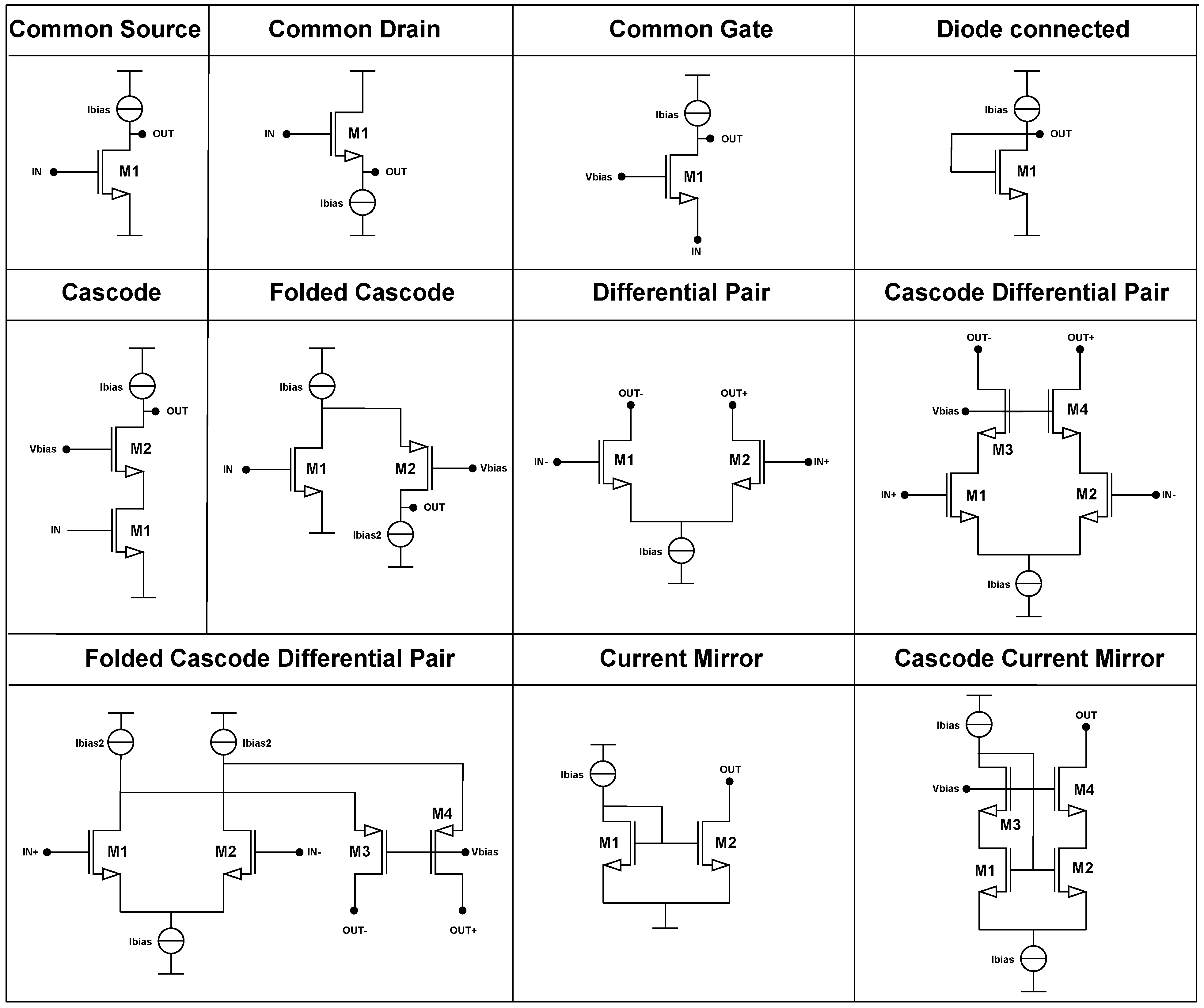
The primitives, which are shown in the Figure 1, serve as building blocks for more complex subcircuits, which in turn are composed into complete analog systems. Each block fulfills a dedicated role within the circuit and can be characterized using a small number of electrical parameters, such as gain, impedance, transconductance, or current consumption. This abstraction enables early specification of requirements at the system level and modular verification at the block level.
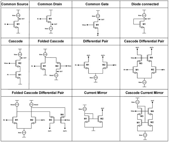
Figure 1.
Primitive table.
In the structured methodology, the set of analog primitives is classified into three main categories, based on their role in circuit operation:
- Amplification Structures: These include differential pairs, simple gain stages, and cascode amplifiers. Their purpose is to provide voltage amplification and signal processing.
- Load and Bias Structures: This group includes resistive loads, current mirrors, and cascode current mirrors. They define the output impedance and enable current control and replication.
- Biasing Networks: These comprise voltage bias stacks and startup circuits, ensuring proper operating points for active devices throughout the system.
A key advantage of the structured approach is that the number of fundamental building blocks is finite, and their behavior is well understood. By combining them in a hierarchical manner, designers can construct complex circuits with predictable properties. This supports hierarchical reasoning, reuse, and facilitates automation [20,21].
In this work, structured design is used to define a macromodel library, where each macromodel encapsulates a functional block defined by:
- A symbolic netlist derived from a small-signal model;
- A set of internal electrical variables;
- Exploratory parameters (e.g., currents, dimensions);
- A connection interface to other macromodels or primitives.
This organization enables the proposed methodology to operate in a recursive manner, exploring local design spaces, verifying constraints, and propagating specifications throughout the system in a scalable and reusable fashion.
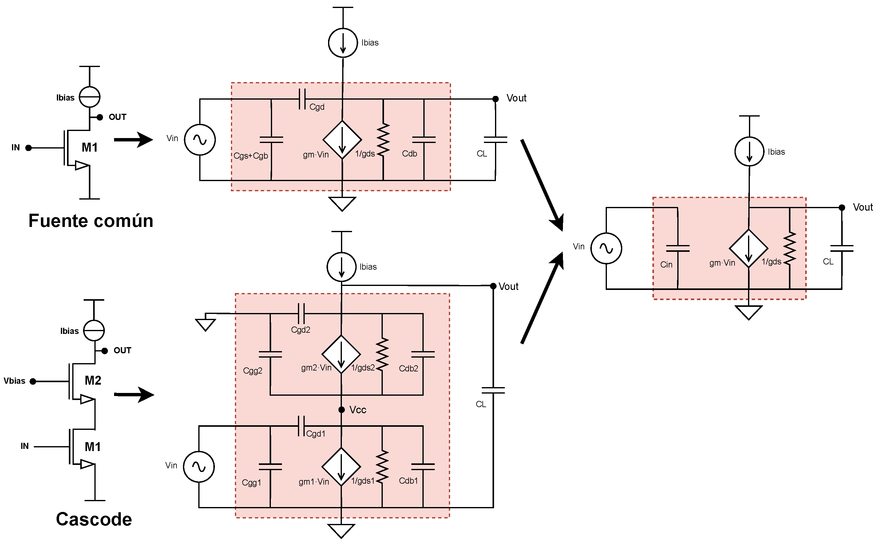
An additional contribution of this work to structured design is the introduction of a higher level of abstraction, where different primitives can be represented through a common symbolic structure, provided that their electrical parameters are redefined according to the specific topology. For example, a common-source configuration and its cascode counterpart can share the same simplified symbolic model once their small-signal representations are replaced and further reduced. As shown in Figure 2, this leads to an identical structural model with distinct expressions for parameters such as , and . This approach differs from traditional structured design that was presented in [19], where separate strategies are defined for each primitive without applying a unified abstraction. Instead, this unified symbolic structure simplifies the treatment of basic blocks within the automated flow.
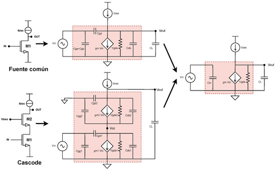
Figure 2.
Primitive simplification example.
Nevertheless, while structured design facilitates hierarchical organization and the derivation of electrical equations, it remains insufficient for transistor sizing. This step still relies on analytical models such as the quadratic approximation or EKV model, which present several limitations; they require specific algebraic manipulation for each block, do not scale easily to more complex structures, and lose accuracy in modern technologies where these models fail to capture the true behavior of transistors.
These limitations motivate the transition to systematic design, which addresses sizing directly using preprocessed technological data via LUTs and design space exploration techniques, as detailed in the following section.
2.2. Systematic Design
Systematic analog design refers to a methodology where electrical specifications guide the selection of circuit parameters using formalized models and structured procedures [22]. Rather than relying on trial-and-error or designer intuition, this approach establishes direct relationships between performance metrics and electrical quantities such as transconductance, output resistance, or bias current.
A key element of systematic design is the use of analytical equations or precharacterized data to estimate the behavior of a circuit block without the need for full transistor-level simulations at each step. For instance, expressions for gain, bandwidth, or output swing can be derived from simplified small-signal models and used to constrain the values of internal variables before committing to device-level implementations.
Systematic design supports techniques such as:
- -based design, where the ratio between transconductance and drain current determines device sizing and inversion level;
- Voltage/current domain separation, which simplifies the estimation of biasing and signal parameters;
- Lookup Tables (LUTs) derived from PDK-level simulations, enabling accurate prediction of electrical parameters over a wide range of operating points.
In this context, systematic design serves as a sizing philosophy that can be integrated into automated frameworks. It enables fast evaluation of circuit configurations, supports constraint-driven design, and improves portability across different process technologies.
The methodology proposed in this work builds upon these principles to structure local block-level exploration based on symbolic models and precomputed data, as further discussed in Section 3.
2.3. Symbolic Analysis and MNA
Symbolic analysis is a technique that derives analytical expressions describing the electrical behavior of a circuit using algebraic manipulation rather than numerical simulation. In this work, the analysis is based on the MNA method, which constructs a system of equations relating the voltages and currents at each node of the circuit.
Each analog block is represented by a symbolic netlist, where components are modeled using their small-signal equivalents. For example, MOSFETs may be abstracted using transconductance () and output resistance (), while current sources and resistors are inserted directly as algebraic terms. The MNA process then systematically generates a set of equations of the form:
where the matrix A contains symbolic expressions involving parameters like gm, ro, and load resistance, and the vector x contains the node voltages or currents of interest. Solving this system yields transfer functions, gains, impedances, and other circuit characteristics in symbolic form. This representation enables:
- Insight into parameter dependencies, showing how performance metrics evolve with design variables;
- Efficient local exploration, where symbolic equations can be evaluated rapidly over different input values;
- Compatibility with automation, as the symbolic form can be programmatically manipulated to extract or verify electrical constraints.
The symbolic analysis is performed automatically using Python3.10-based tools, enabling each block in the design to be characterized algebraically before committing to numerical validation or transistor-level implementation.
2.4. Lookup Tables (LUTs) for Design Exploration
The use of LUTs is a well-established technique in systematic analog design to avoid expensive iterative simulations. LUTs store precharacterized data obtained through sweeping transistor parameters under specific process design kits (PDKs), enabling the retrieval of electrical parameters such as transconductance, output resistance, or saturation voltage for given device dimensions and bias conditions.
In the proposed methodology, LUTs are used to provide accurate device-level data for primitive blocks during the exploration phase, enabling rapid evaluation of design alternatives while preserving PDK fidelity. This allows each macromodel to transition from an estimated symbolic model to a numerically accurate instance once the primitives are resolved.
3. Proposed Methodology
This work proposes a methodology that integrates the principles of structured design and systematic analog design to enhance the automation of analog circuit sizing. The key concepts behind these approaches were introduced in Section 2.1 and Section 2.2.
From structured design, the methodology adopts the hierarchical decomposition of the circuit into functional blocks called macromodels. Each macromodel may contain internal sub-macromodels or terminal primitives. It also incorporates the derivation and propagation of specifications, allowing design constraints to be transferred from the system level down to the fundamental circuit elements. This modular structure facilitates the analysis, optimization, and reuse of analog blocks.
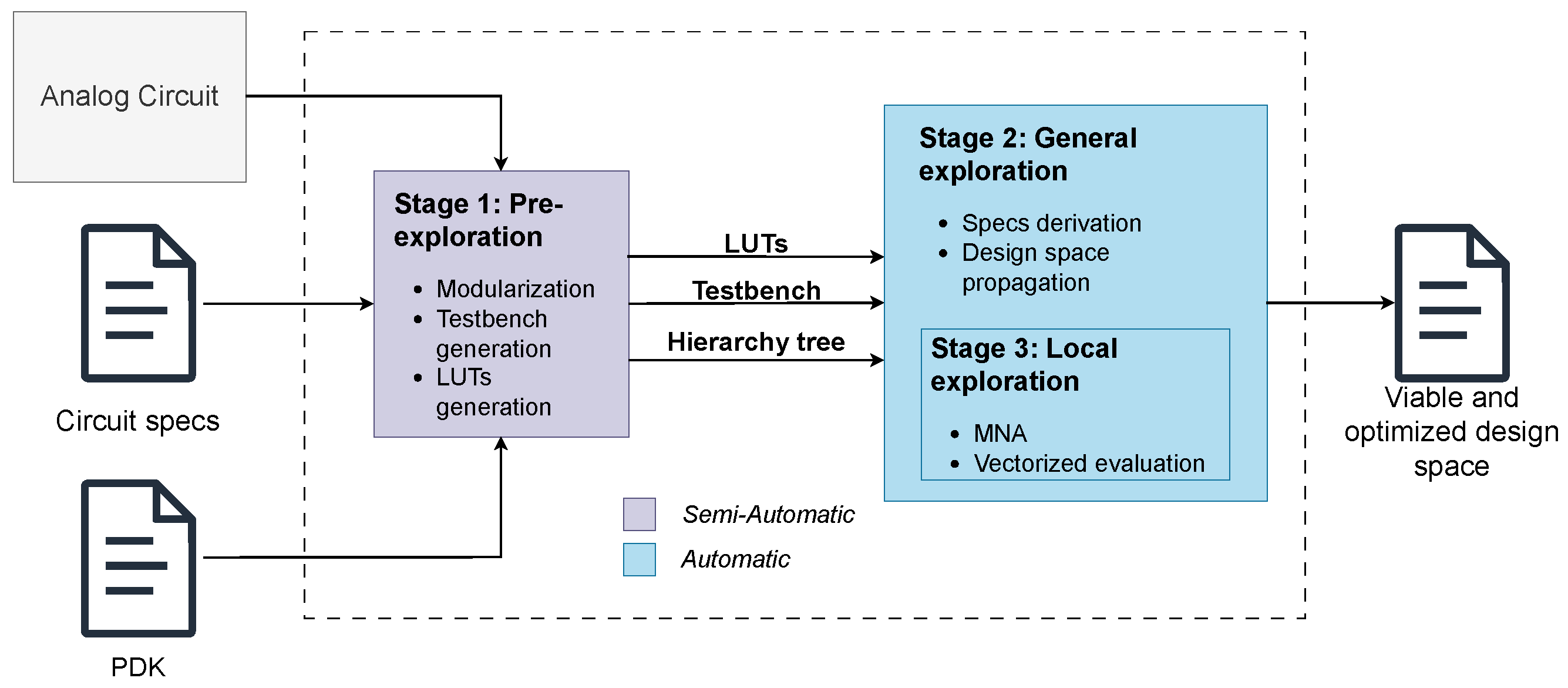
From systematic design, the methodology introduces efficient design space exploration based on LUTs, reducing reliance on iterative SPICE simulations. This significantly shortens the exploration time and removes the need for manual tuning in each design iteration. The methodology is organized into three main stages, as illustrated in Figure 3:
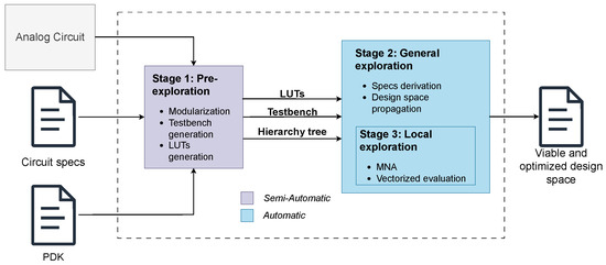
Figure 3.
General flow diagram.
Stage 1—Pre-exploration: The circuit is decomposed to build the hierarchical tree. Testbenches are defined, and the technology-specific LUTs are generated. LUT generation is the only automated step in this initial stage.
Stage 2—Global exploration—derivation of specifications: The hierarchy tree is explored. Specifications are propagated and feasible solutions are filtered.
Stage 3—Local exploration: While technically part of the global exploration, this is the core optimization step, responsible for generating the full design space that will later be constrained and filtered.
3.1. Stage 1: Pre-Exploration
The first stage of the proposed flow is responsible for preparing all necessary circuit data and models prior to automated exploration. This includes the modularization of the circuit, the definition of testbenches for each block, and the generation of technology-specific Lookup Tables (LUTs).
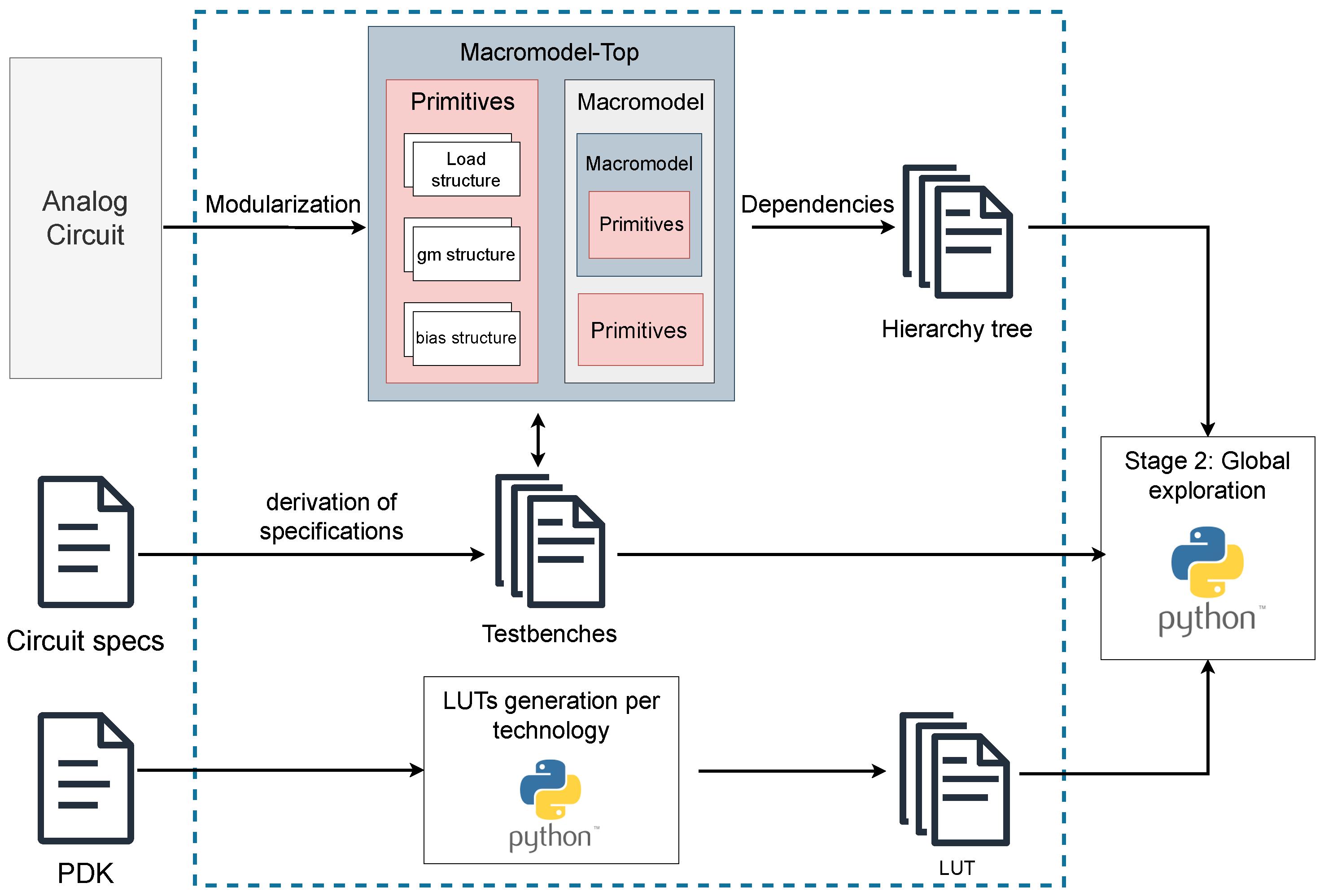
The process is shown in the Figure 4 and begins with the modularization of the circuit, performed following the same principles presented in structured analog design. The circuit is decomposed into functional blocks—referred to as macromodels—and organized into a hierarchy tree that captures the dependencies between macromodels, submacromodels, and terminal primitives at each level. This tree serves as the structural foundation for managing the flow of specifications and guiding the exploration process across the design.
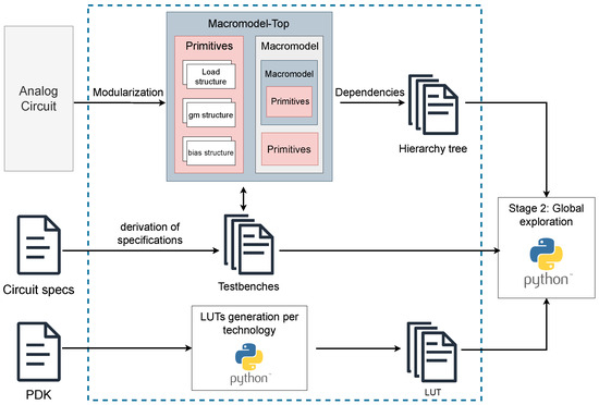
Figure 4.
Stage 1 diagram.
Next, testbenches are defined to evaluate each macromodel according to its specifications. These are SPICE-compatible circuits that include the necessary stimulus and connections to simulate the behavior of the block in isolation, avoiding the need for manual equation solving. Since each macromodel must meet specific design objectives, a dedicated testbench is created for every level in the hierarchy. This stage also includes an automated LUT generation process. For each device and technology under consideration, a Lookup Table is created using Python scripts that drive controlled simulations to extract key electrical parameters. Once configured, this process runs autonomously, allowing systematic LUT generation across multiple PDKs with minimal manual input. This preparatory stage ensures that all structural and electrical data required for the next phases of the methodology are correctly established and formatted.
3.2. Stage 2: Global Exploration
The second stage of the proposed flow corresponds to the global exploration, where the hierarchy of macromodels and primitives defined in the previous stage is systematically explored. During this phase, the parameters of each macromodel are optimized in a hierarchical fashion, ensuring consistency with the structural constraints imposed by the circuit. This stage follows a bidirectional exploration strategy that combines two complementary analysis flows:
- Top-down flow (Specification derivation): Circuit specifications are propagated from the top level down to the primitives at the base of the hierarchy, defining constraints for each macromodel and subblock.
- Bottom-up flow (Design space propagation): Once the lower levels are evaluated, the results are propagated upward, updating and optimizing the parameters of higher-level macromodels.
The strategy minimizes the number of evaluations required. In the top-down flow, the number of combinations does not grow exponentially since it depends only on the default parameters of submacromodels. However, in the bottom-up direction, if the design space is not properly filtered, the number of combinations can increase exponentially, impacting computational efficiency and execution time.
To traverse the hierarchy efficiently, the global exploration uses a Depth-First Search (DFS) algorithm [23]. This allows each macromodel to be evaluated while ensuring that derived constraints are correctly propagated, improving convergence toward optimal solutions.
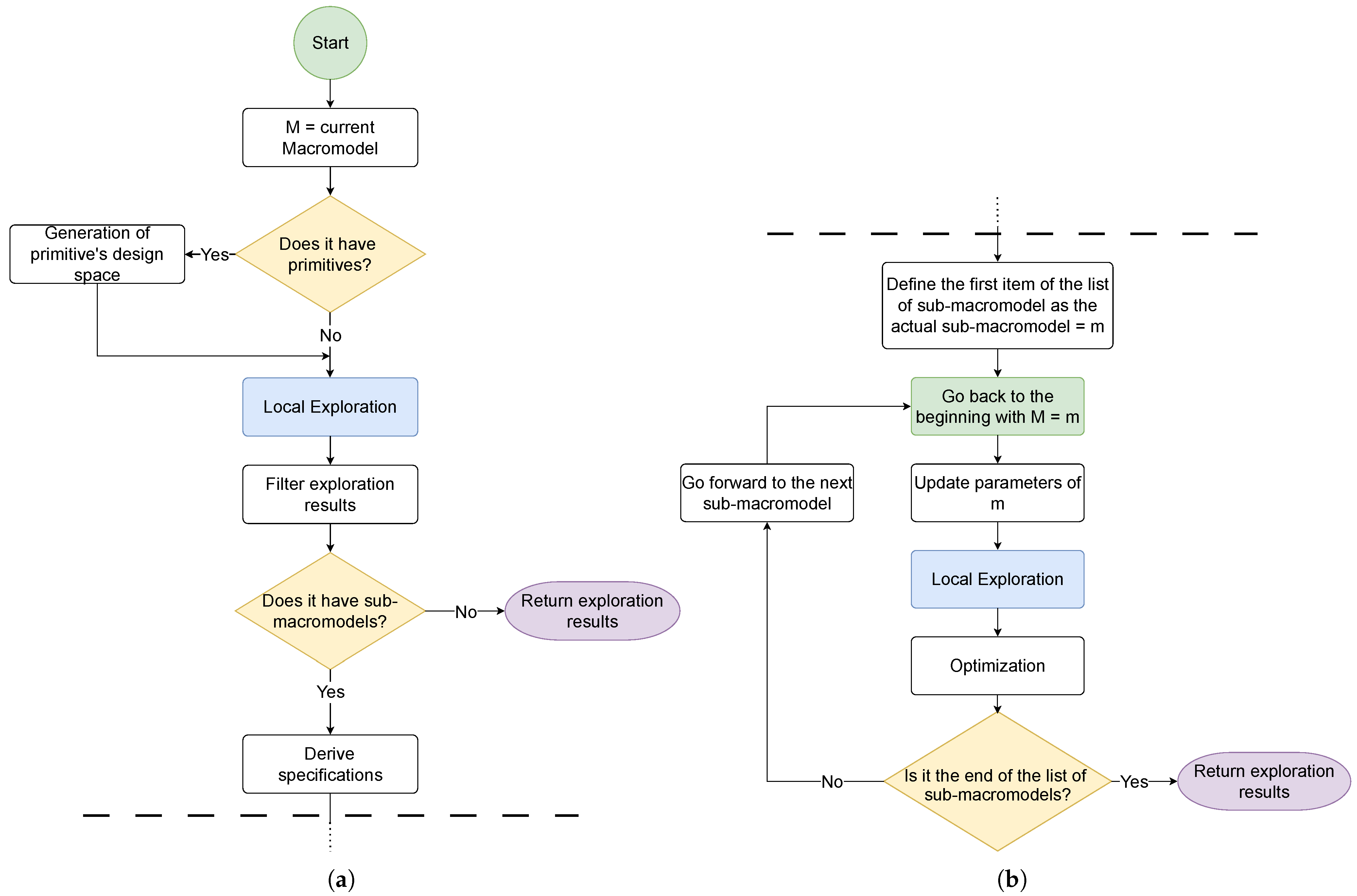
The top-down process is shown in Figure 5a and consists of the following steps:
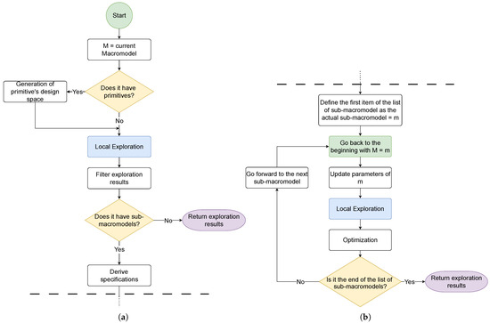
Figure 5.
Stage 2 diagram. (a) Top-down flow. (b) Bottom-up flow.
- Select the current macromodel under evaluation.
- If the macromodel contains primitives, generate its corresponding design space.
- Perform local exploration using predefined parameters and the values obtained from its primitives.
- Filter the results to ensure compliance with design constraints.
- If the macromodel contains submacromodels, derive new constraints from the exploration results.
- Use these derived constraints to explore the submacromodels, repeating the process until the lowest level is reached.
The bottom-up process, which is shown in the Figure 5b, proceeds as follows:
- Once a macromodel with no submacromodels is reached, return its exploration results to the next level up in the hierarchy.
- Use the obtained values to update previously predefined parameters in the parent macromodel.
- Re-optimize the results to meet the derived specifications.
- If another adjacent macromodel exists, mark it as next and resume the global exploration flow.
This mechanism maintains consistency with system-level constraints by restricting the design space at each hierarchical level based on lower-level results. To avoid exponential growth in parameter combinations, design space filtering is applied using top-down constraints and optimization criteria that prioritize efficiency in power, area, and performance. As a result, the system focuses only on feasible configurations, significantly enhancing exploration efficiency.
3.3. Stage 3: Local Exploration
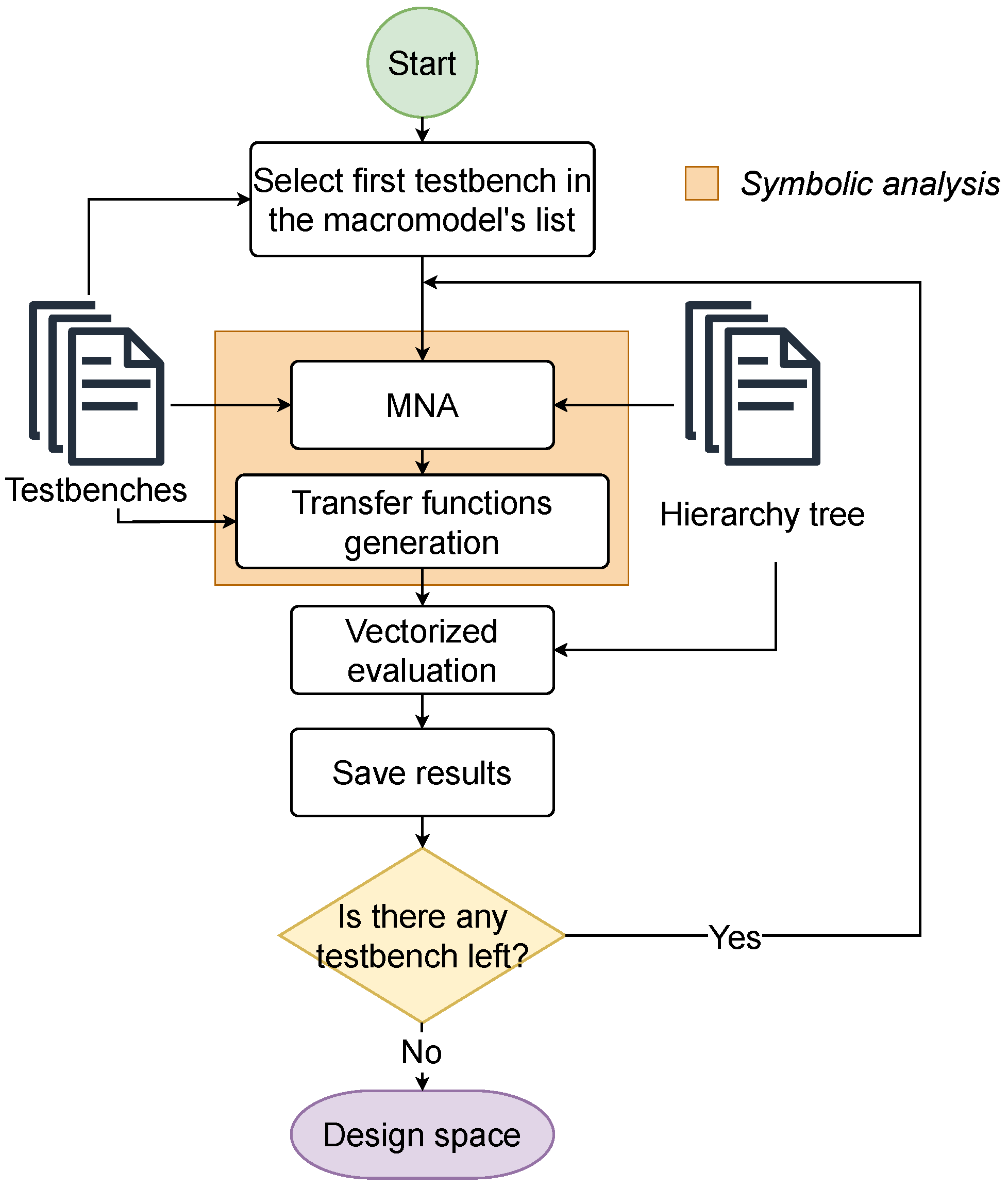
The diagram of this stage is shown in Figure 6; each macromodel is analyzed individually using its corresponding testbench. The analysis considers both the internal electrical parameters of the block and its hierarchical dependencies with other subcircuits. The process involves two main steps:
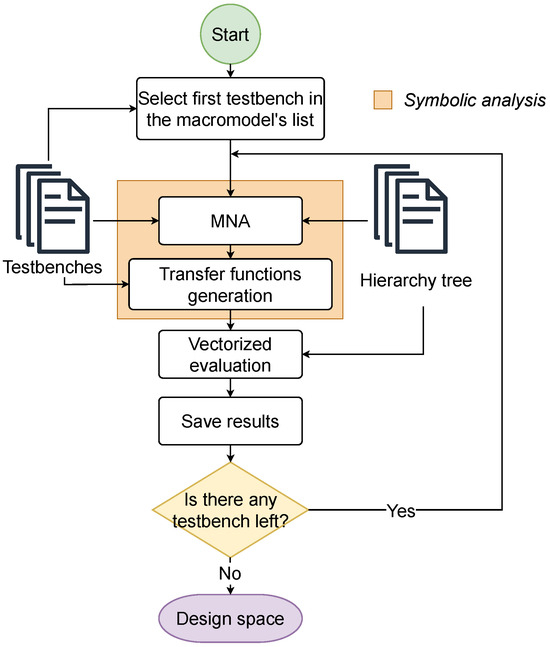
Figure 6.
Stage 3 diagram.
- Symbolic analysis: This step extracts the system of equations that describe the behavior of the testbench using MNA. Solving the resulting linear system enables the explicit definition of the transfer function or any other target equation required for the design objective.
- Vectorized evaluation: Once the symbolic equations are formulated, all design-space equations are computed in a single batched array operation, treating the parameters set as arrays. This eliminates explicit Python loops and accelerates the exploration.
This stage takes as input the hierarchy tree, which defines the structural composition of the circuit, and the testbenches, which contain the specifications that each macromodel must satisfy. Together, these inputs and processes enable the local optimization of each block within the context of the global design constraints.
4. Implementation
4.1. Context and LDO Architecture
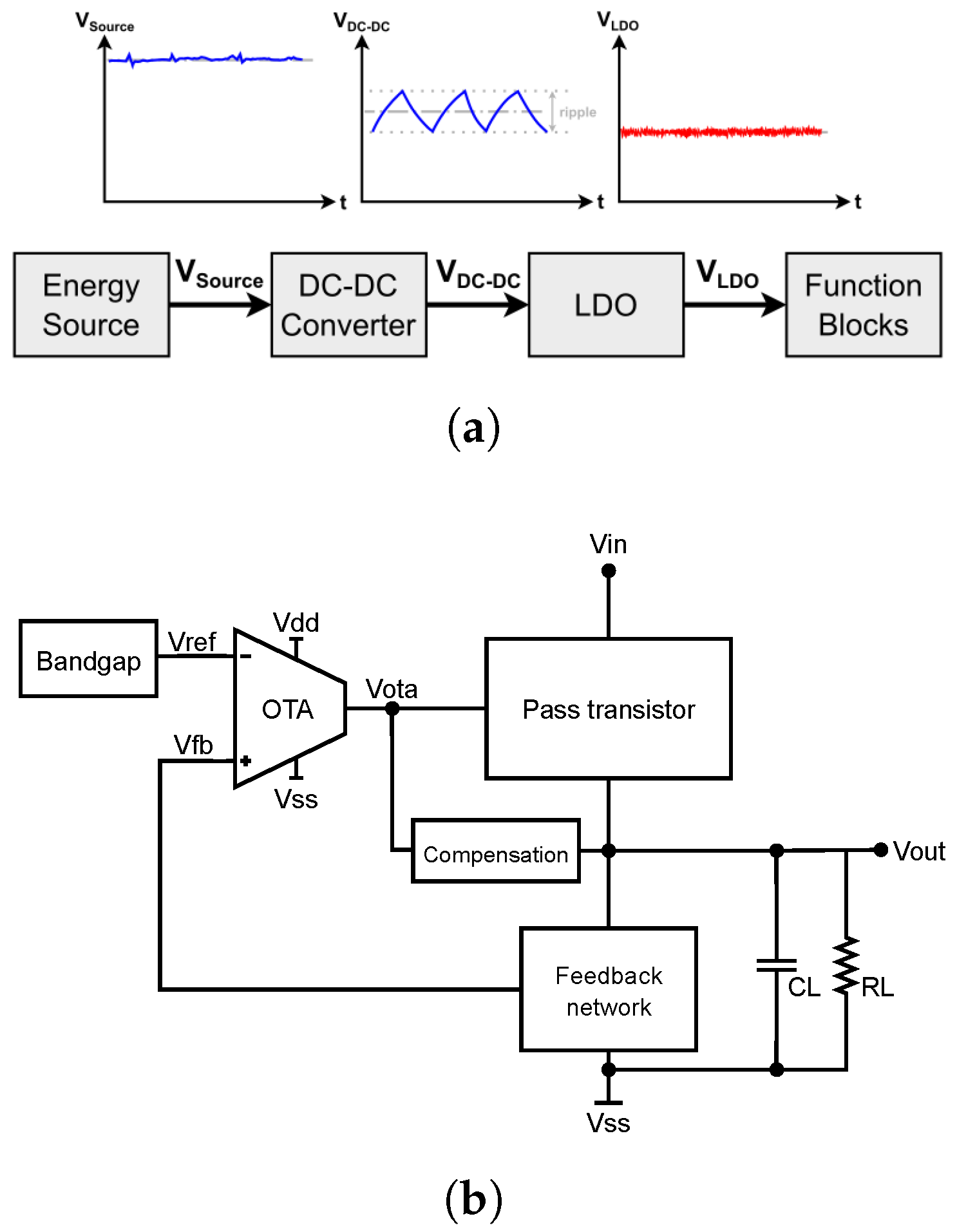
Low Dropout Regulators are a key component of integrated DC-DC power management systems [7]. Unlike switching converters, LDOs provide low-noise, linear regulation, making them essential for powering sensitive analog or mixed-signal blocks within system-on-chip (SoC) designs. Their fully integrated implementation simplifies system complexity and reduces area and electromagnetic interference (EMI), but also imposes stricter constraints on performance metrics such as dropout voltage, power supply rejection ratio (PSRR), and loop stability [24].
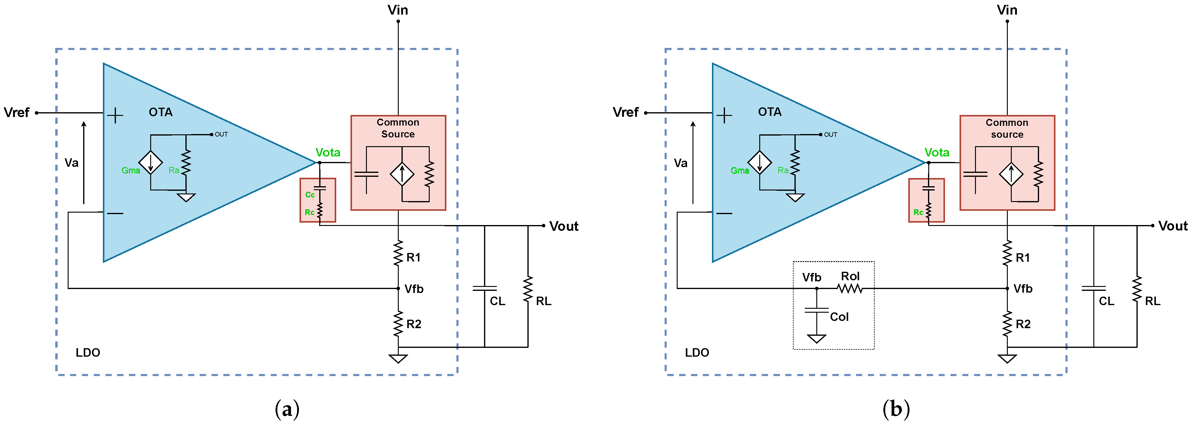
A typical integrated LDO, as shown in Figure 7b, comprises three main building blocks:
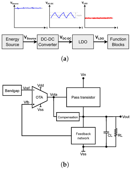
Figure 7.
LDO context and configuration. (a) LDO operation in a DC-DC system [7]. (b) Basic LDO topology.
- Error Amplifier: Compares the output voltage with a reference and amplifies the error.
- Pass Element: A power transistor (typically PMOS or NMOS) that regulates the current flow from input to output.
- Feedback Network and Compensation: Sets the regulation point and ensures stability.
The pass element dominates power efficiency and dropout voltage, while the error amplifier defines loop gain and dynamic response. These blocks must be co-designed to meet the overall specifications under varying load and supply conditions.
4.2. Design Objectives
The design specifications adopted in this work were derived from a review of recent literature on fully integrated DC-DC power management systems. Based on the typical constraints of on-chip analog supplies, a set of target performance metrics was defined to guide the design space exploration and architectural choices [25,26,27].
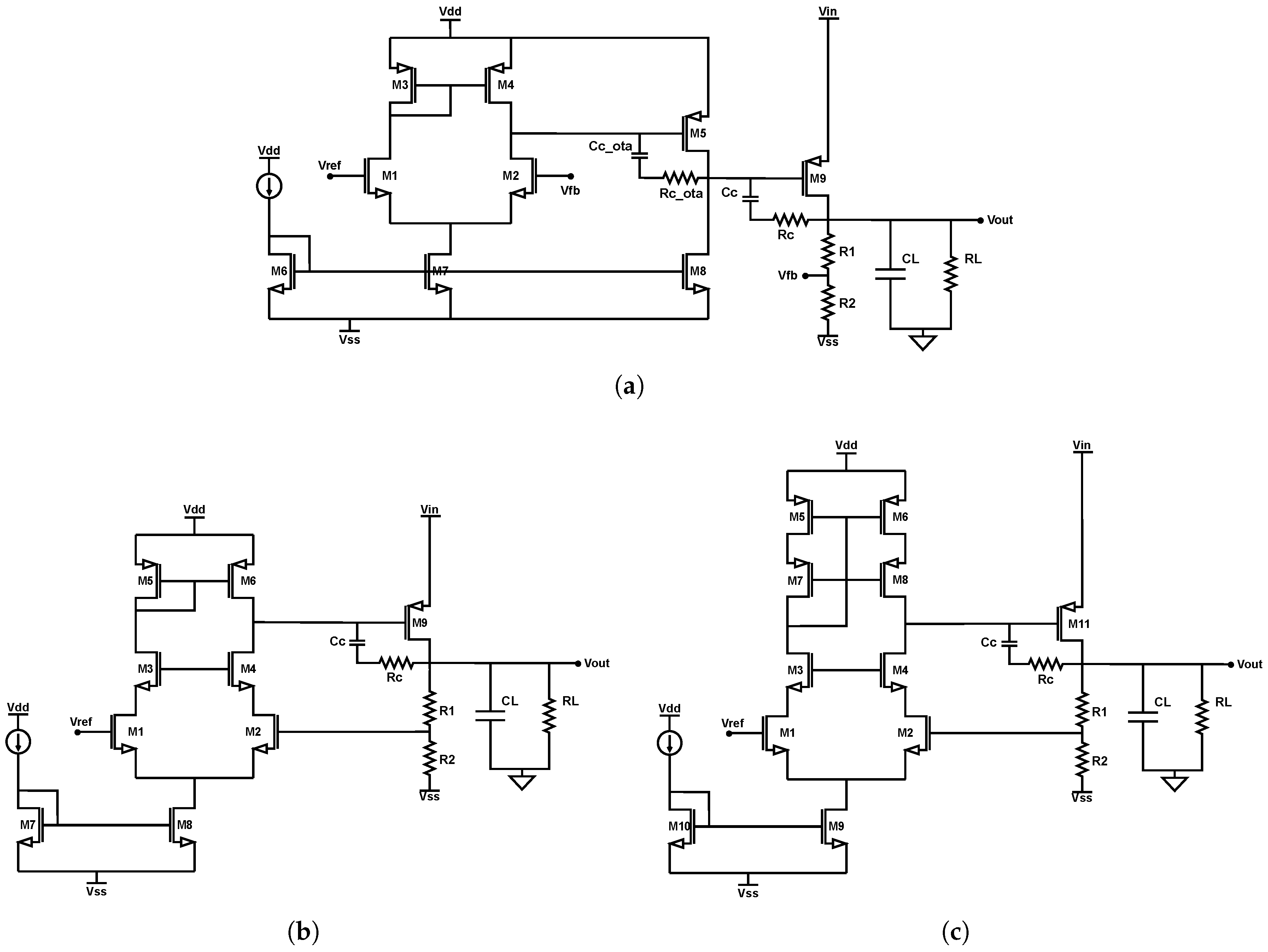
In addition to numerical specifications, three LDO topologies were selected to validate the flexibility of the proposed methodology:
- Topology A (Figure 8a): Two-stage amplifier Miller OTA With PMOS pass device.
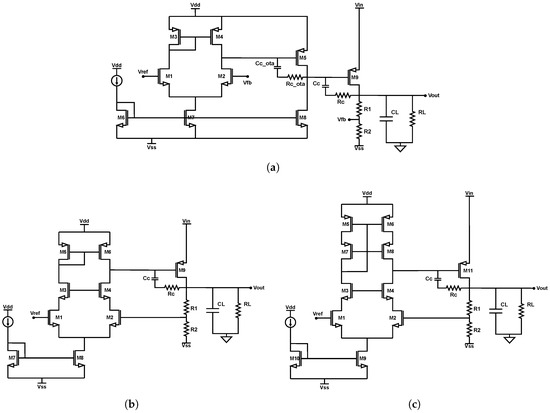 Figure 8. Topologies to be explored. (a) LDO with a two-stage Miller OTA. (b) LDO with a one-stage OTA but a differential cascode. (c) LDO with telescopic OTA.
 - Topology B (Figure 8b): Single-stage amplifier with a basic error amplifier and PMOS pass device.
- Topology C (Figure 8c): Folded cascode amplifier and PMOS device.
These architectures differ in complexity, stability behavior, and transistor count, making them ideal for testing the generality of the methodology across a range of realistic design challenges. The target design metrics for all topologies are summarized in the Table 1. There are some fixed values such as , , , and parameters such as in Table 1, which are not design-optimization parameters but design objectives. The rest are also optimization parameters. These optimization parameters were enforced during the automated sizing and evaluation stages of the methodology, and all topologies were tested under the same conditions to ensure comparability across designs and technologies. They were enforced during the automated sizing and evaluation stages of the methodology, and all topologies were tested under the same conditions to ensure comparability across designs and technologies. Due to space constraints, the following implementation analysis focuses on Topology A using the IHP SG13G2 technology. However, the same exploration process is applied to the other two topologies, and evaluating different technologies requires only replacing the LUTs, thanks to the structured and modular nature of the proposed methodology.

Table 1.
Design objectives of the LDO.
Throughout this paper, the term “area” denotes a size metric defined as the width W plus the length L of every transistor, following [12]. This choice emphasizes variations in device sizing during schematic-level exploration of analog circuits, where .
4.3. Stage 1 Implementation
In this section the first step of the proposed methodology is implemented. It begins with the decomposition of the LDO into functional blocks, followed by the definition of testbenches for each macromodel, and concludes with the generation of technology-specific Lookup Tables (LUTs).
4.3.1. Modularization
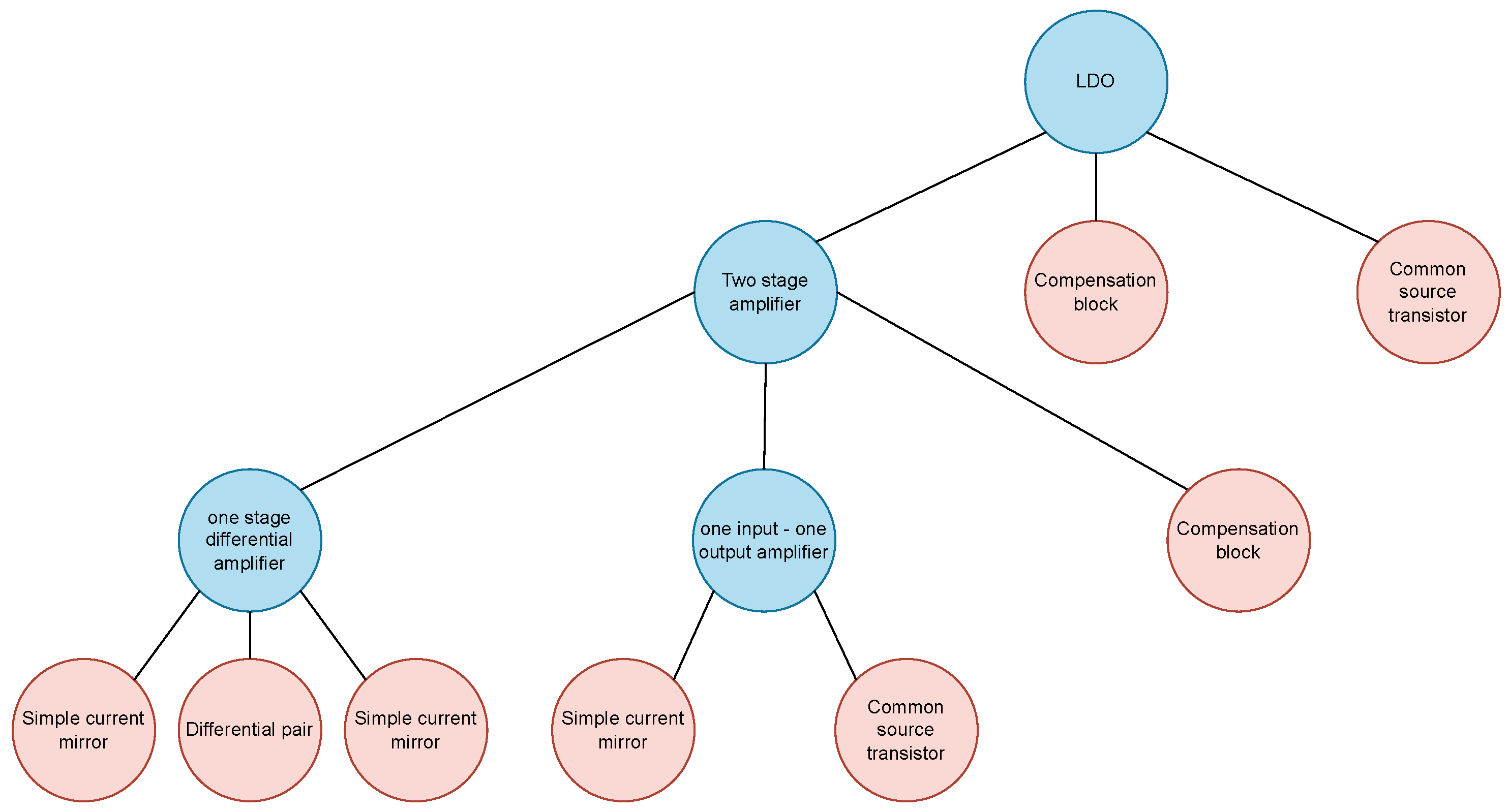
The LDO circuit was decomposed into functional blocks following the structured design methodology introduced in Section 2.1, as shown in the Figure 9. The modularization was performed from the top level, identifying the primary macromodel as the full LDO regulator, which is then divided into three key sub-blocks: the error amplifier, the pass device, and the compensation network. The resistive feedback network is not considered a key sub-module. Its divider ratio is predetermined by the specified output and reference voltages, and the resistor values are set once and kept fixed (not optimization parameters) throughout the exploration.
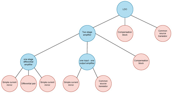
Figure 9.
LDO hierarchy diagram.
Each of these sub-blocks was further broken down into sub-macromodels or primitives, depending on their complexity and level of abstraction. For example, the error amplifier includes multiple gain stages and biasing structures, while the pass device and compensation blocks are typically modeled using simpler primitives or fixed-parameter blocks.
This decomposition results in a hierarchy tree that defines the dependencies between blocks and allows recursive execution of the design flow. Local specifications can be defined at each level, enabling targeted exploration and optimization while maintaining consistency with system-level requirements.
4.3.2. Testbenches
To evaluate each macromodel against its target specifications, dedicated SPICE-compatible testbenches were created. These testbenches allow small-signal analysis and ensure that the defined metrics can be extracted automatically during the design space exploration.
Four specifications were selected as primary targets for the main LDO macromodel: PSRR, Dropout, load regulation and phase margin. PSRR was evaluated using a testbench that applies an AC signal at the power supply input in the closed loop configuration, as shown in Figure 10a, Dropout was directly extracted from the pass transistor primitive, load regulation uses the same configuration as PSRR but as the difference between two DC operating points, while the phase margin was measured by breaking the feedback loop using high-value series components (, ) that preserve DC bias while isolating the loop in small-signal, as shown in Figure 10b.
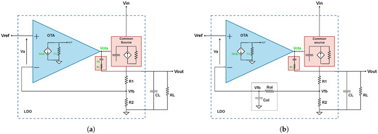
Figure 10.
LDO macromodel testbenches. (a) Closed-loop testbench configuration. (b) Open-loop testbench configuration.
For the two-stage amplifier macromodel, the testbenches targeted gain, output resistance, equivalent transconductance, and phase margin. Gain and output resistance were measured using distinct small-signal testbenches, while transconductance was computed by dividing gain by output resistance. Each macromodel also includes internal degrees of freedom—electrical variables or parameters not directly defined by the specifications. These variables are swept during the exploration phase to identify feasible operating regions within the allowed design space.
4.3.3. LUT Generation
LUTs were generated for each of the three target technologies. For IHP-SG13G2, low-voltage (1.8 V) NMOS and PMOS devices were used. For Sky130A, low-threshold voltage (LVT) devices at 1.8 V were selected to enhance operation in moderate inversion. In GF180MCU, the lowest-voltage available devices were 3.3 V transistors, as no shorter-channel devices are available at lower voltages.
Device characterization was carried out by sweeping electrical variables while keeping the transistor width W constant, selected to match the expected operating region. Execution times for generating each LUT were 19 s (IHP-SG13G2), 1 min 50 s (Sky130A), and 21 s (GF180MCU). For NMOS vs. PMOS, the only difference in the sweep configuration was the sign of the applied voltages (positive for NMOS, negative for PMOS).
4.4. Stage 2–3 Implementation
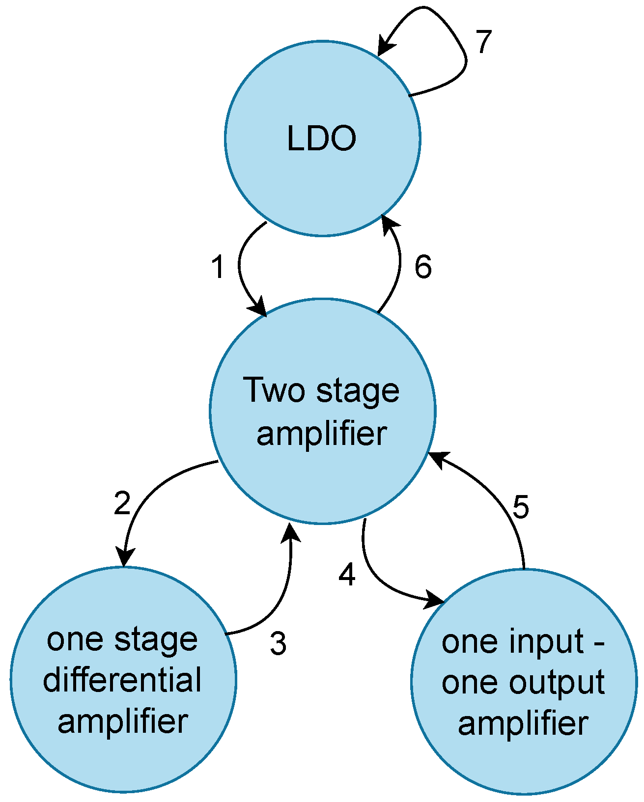
To illustrate the operation of the proposed methodology, this section presents a graphical overview of the exploration sequence across the LDO hierarchy. Figure 11 shows the order in which local explorations are performed, as determined by the global exploration process implemented in Stage 2 of the methodology.
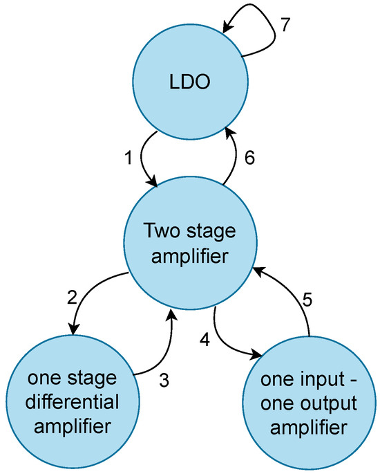
Figure 11.
Transition flow diagram extracted from global exploration. The numbers represents the order of the transitions.
In the diagram, each arrow represents a transition between macromodels. When the direction is from a higher-level to a lower-level macromodel, it corresponds to the propagation of specifications. Conversely, arrows from a lower to a higher level indicate the propagation of resolved design parameters back up the hierarchy.
While the figure summarizes the full sequence of transitions, only a subset of key steps will be presented to exemplify how the methodology filters the design space and updates parameters throughout the hierarchy.
The diagram is provided solely as a visual aid, as all transitions and calculations are performed automatically by the flow. The next subsections describe representative transitions that showcase the methodology in action.
4.4.1. Exploration Results
This section presents a selection of key transitions from the LDO hierarchy, each illustrating essential steps of the exploration process. For conciseness, only the most representative transitions are shown, highlighting the hierarchical flow, the propagation of specifications, and the resolution of design parameters.
Transition 1: From LDO to Error Amplifier
The first local exploration is performed on the top macromodel. The exploratory parameters include the OTA output voltage () and the pass transistor channel length (), which define the design space for the pass transistor. Default values for and are used in the simplified OTA model.
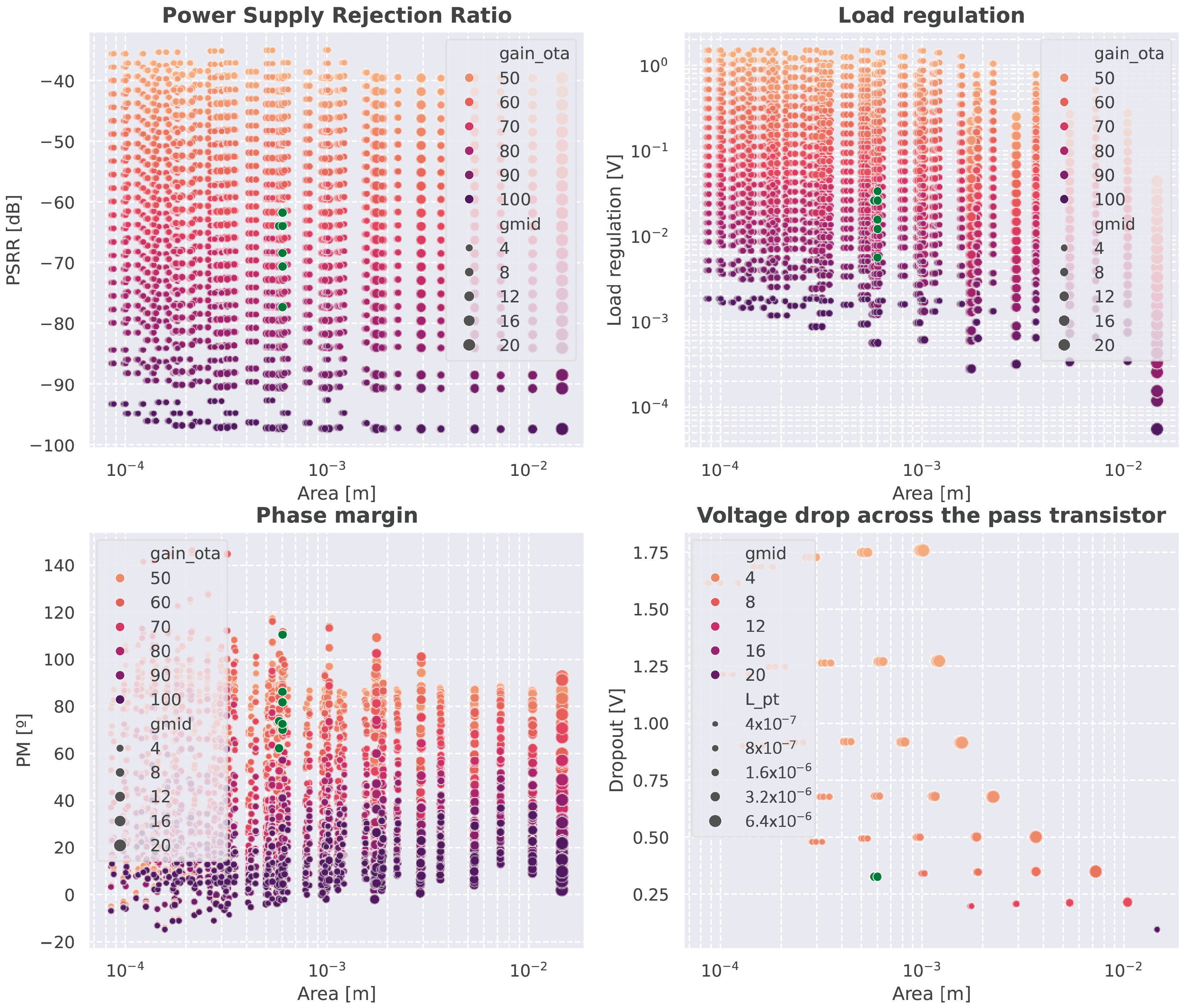
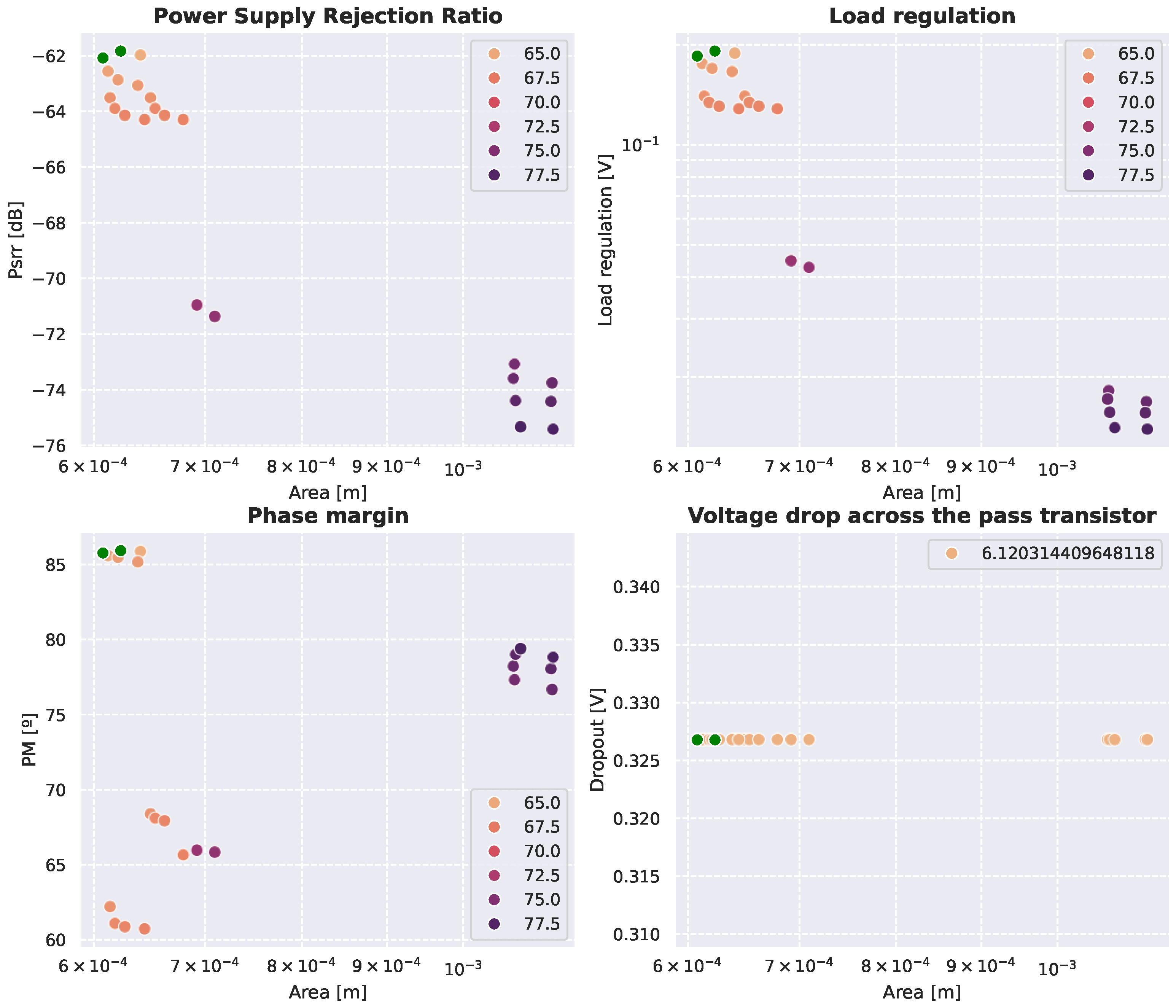
A total of 45,000 points were evaluated, resulting in a single pass transistor configuration that satisfies the specifications, with dimensions of m and m. This directly sets unique values for and the pass transistor input capacitance , eliminating degrees of freedom for these variables in subsequent stages and significantly reducing the design space.
The derived OTA specifications include a minimum gain of 64.4 dB and a bandwidth below 1 kHz. The resulting design space is shown in Figure 12, where it is evident that PSRR, load regulation, and phase margin are strongly dependent on the amplifier’s gain, while the dropout voltage depends exclusively on the pass transistor dimensions.
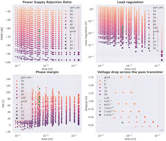
Figure 12.
Design space of the first local exploration. Green dots indicate the points that meet the requirements.
Transition 2 and 3: From Amplifier to Primitives
The second transition corresponds to the local exploration of the two-stage OTA macromodel, using the specifications defined at the LDO level. In this step, 312,000 points were evaluated, but no additional constraints were derived from this exploration.
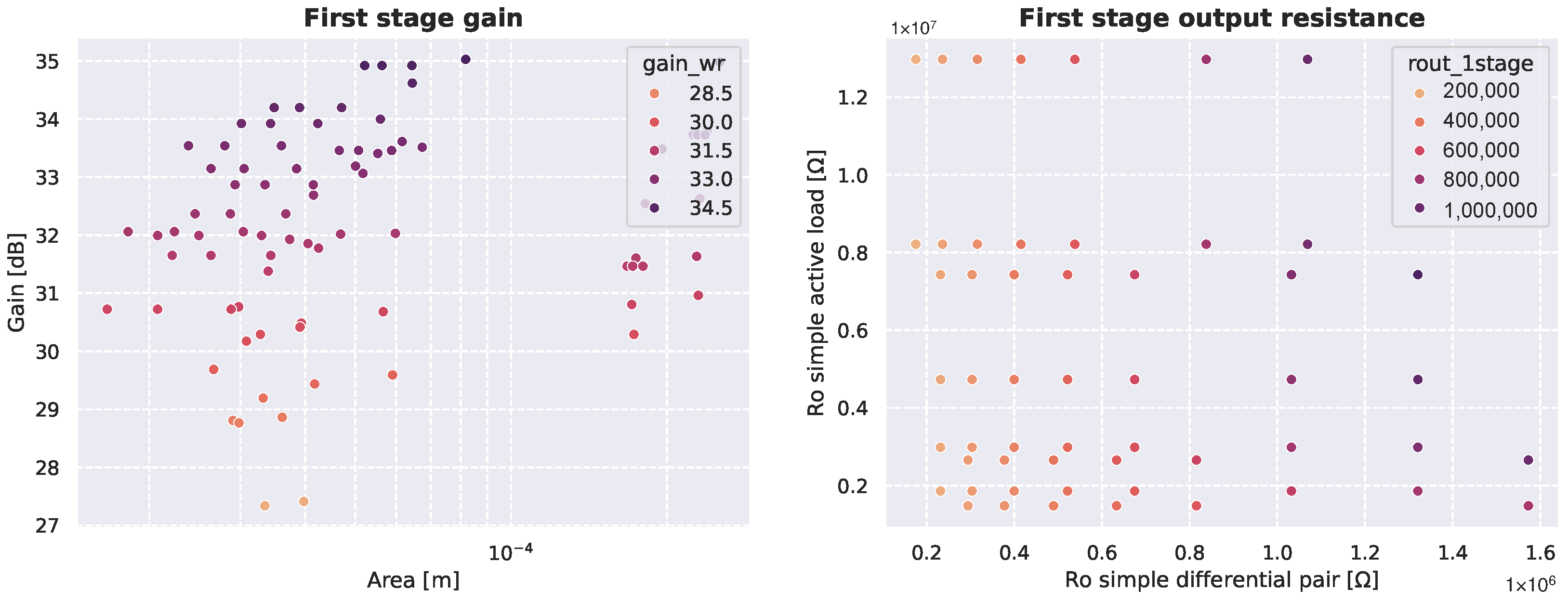
Transition 3 initiates the first propagation of the design space within the hierarchy. Since no specific constraints were passed down from the OTA macromodel, the exploration of its first stage, composed of three primitive blocks, was constrained only by the minimum transistor size requirements. The design space was generated based on the exploratory parameters of these primitives, resulting in 825,000 evaluated points, from which only 410 configurations satisfied the sizing constraints. This represents a 99.95% reduction in the number of candidates.
Figure 13 presents the resulting design space for the single-stage OTA, showing the feasible solutions after this substantial reduction.
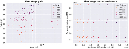
Figure 13.
Design space of the local exploration of the OTA’s first stage.
Transitions 4, 5 and 6: Exploration of Intermediate Blocks
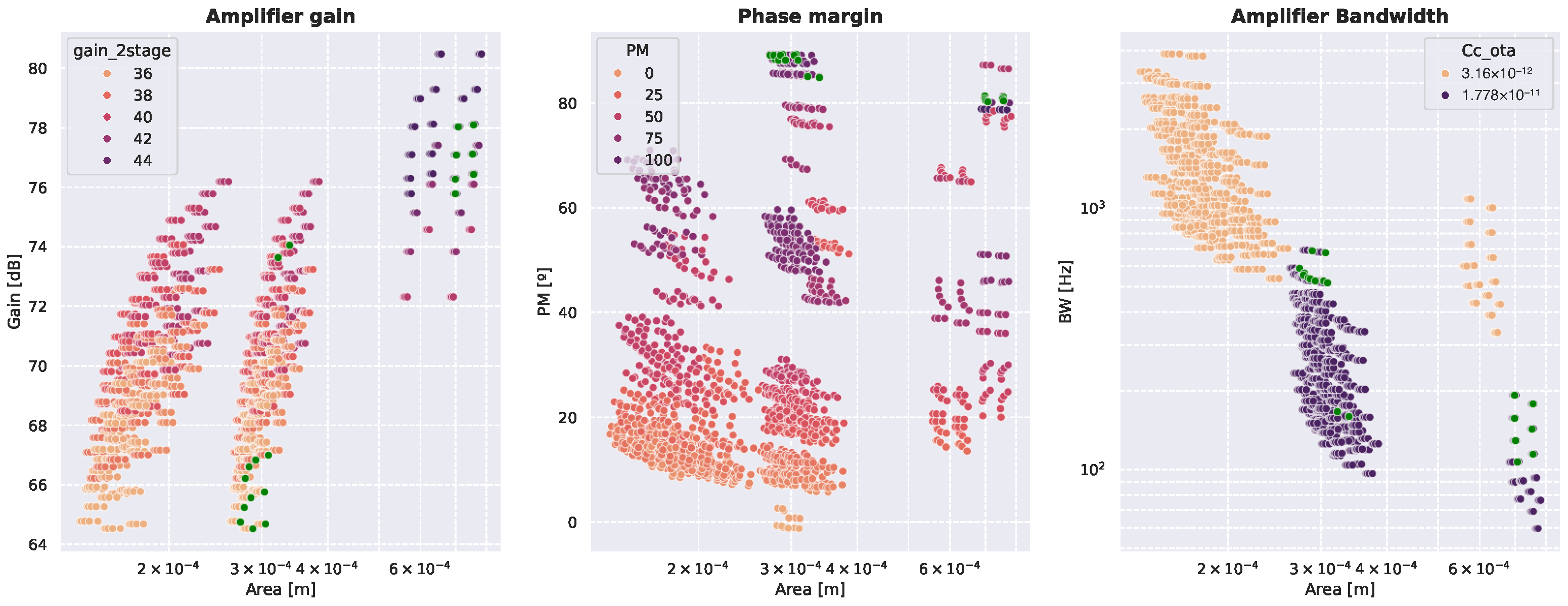
The fourth transition corresponds to a new exploration of the two-stage OTA macromodel, this time incorporating the constraints propagated from the lower levels. From this analysis, new specifications were derived, including a minimum gain of 35 dB for the second stage and a compensation capacitance constrained between 3.16 pF and 17.8 pF. In the fifth transition, the local exploration of the second gain stage was performed, evaluating 3125 points, of which only 46 configurations satisfied all specifications. The sixth transition explores the combined design space of the two gain stages, consolidating the results obtained so far. A total of 188,600 points were evaluated, with only 19 valid configurations meeting the required constraints. At this stage, the complete design space for the two-stage OTA is fully defined, allowing the amplifier to be reused in other designs if needed.
Figure 14 shows the resulting design space for the two-stage OTA after this exploration and filtering. Note that the hierarchical nature of our LDO design example inherently demonstrates the general-purpose capabilities of the framework. For instance, a two-stage Miller OTA is directly generated by it, and the design space is already shown in Figure 14. This can be generalized to other building blocks that rely on the gm/ID technique, such as different amplifier topologies, various LDO topologies, blocks with different specifications, and larger circuits such as analog front-ends.
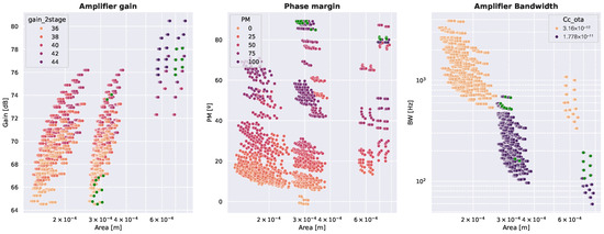
Figure 14.
Design space of the two-stage Miller OTA. Green dots indicate the points that meet the requirements.
Transition 7: Final Resolution of the LDO
Once all subblocks are resolved, the top-level macromodel is validated using the actual values obtained from the primitives. This final transition confirms that the selected configuration satisfies all original specifications, including PSRR and stability.
Figure 15 displays the final filtered solution set for the complete LDO, illustrating how the hierarchical exploration converges to a feasible design that meets all constraints.
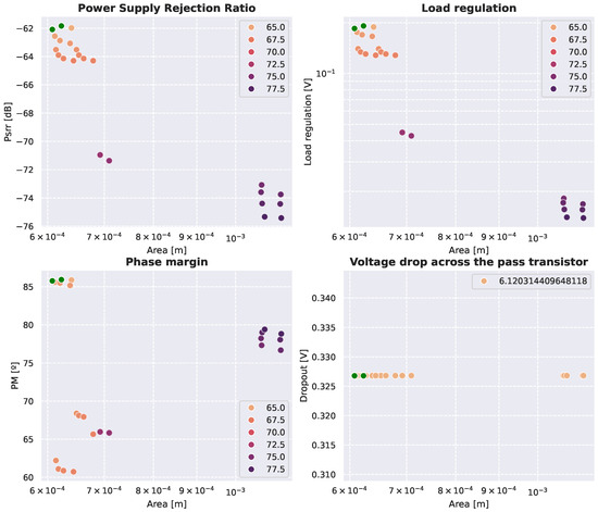
Figure 15.
Final LDO design space. Green dots indicate the Pareto frontiers.
4.5. Evaluation of Alternative Topologies and Technologies
As introduced earlier, three LDO topologies were selected to evaluate the generality of the proposed methodology. After completing the full exploration flow for the two-stage OTA architecture, the same process was applied to the remaining two configurations: a single-stage amplifier with cascode differential pair, and a telescopic OTA. All three designs share the same pass device, which was reused without modification across topologies.
The initial experiments were carried out using the IHP SG13G2 technology. In this case, only the two-stage OTA successfully met all design specifications. The other two topologies failed to provide feasible solutions, primarily due to their increased stacking of transistors. This results in reduced voltage headroom across individual devices, especially in operating points with higher output voltage, which compromises gain and saturation conditions.
To evaluate cross-technology portability, the three topologies were also implemented using two additional open-source PDKs: Sky130A and GF180MCU. With Sky130A, once again only the two-stage OTA yielded valid results. In contrast, all three topologies were successfully explored and resolved using GF180MCU. This can be attributed to the use of 3.3 V transistors in this technology, which offer greater flexibility for stacked designs and improve feasibility margins in headroom-limited scenarios.
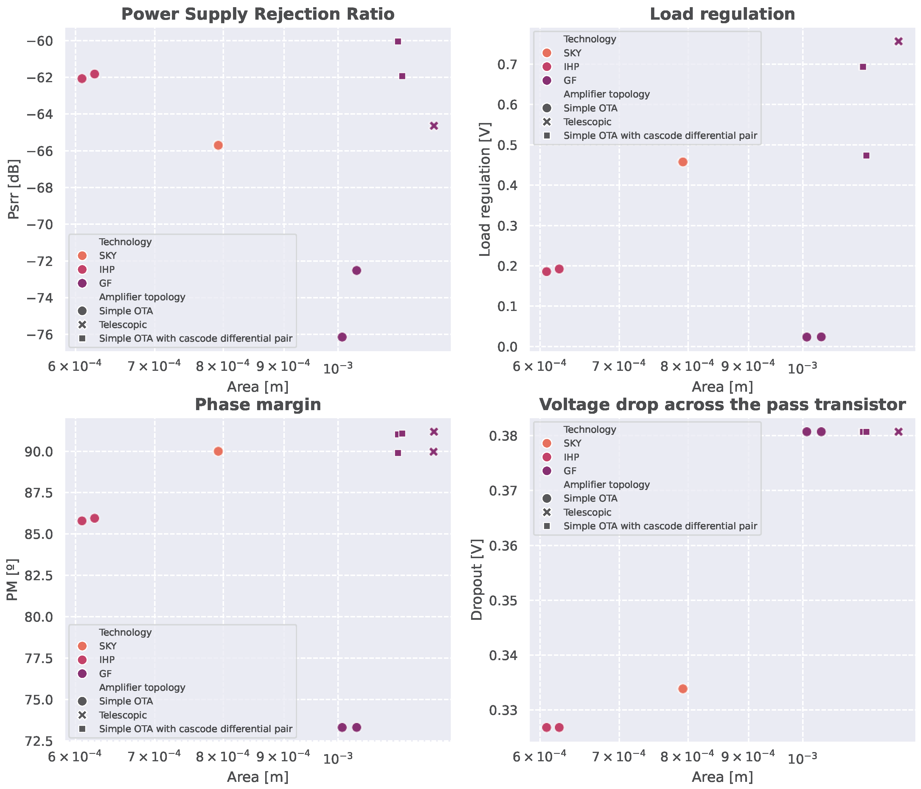
To summarize the performance trade-offs across topologies and technologies, Figure 16 presents the resulting Pareto frontiers. Each point corresponds to a valid configuration that meets the required specifications. In addition, Table 2 details the optimal points in terms of area for each combination of topology and technology. The results show that:
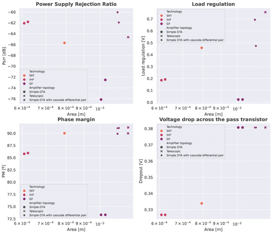
Figure 16.
Design space of the different topologies and technologies.

Table 2.
Minimal-area designs.
- Single-stage OTAs provide higher phase margins due to simpler stability requirements, but generally at the cost of greater area.
- The two-stage OTA achieves a better balance between stability and compactness.
- Among the technologies, IHP SG13G2 enables valid designs with minimal area; Sky130A offers a moderate trade-off; and GF180MCU, while requiring more area, supports all topologies thanks to its higher-voltage devices.
These results confirm the scalability and portability of the proposed methodology across both architectural and technological domains.
5. Conclusions
The proposed methodology successfully enabled the automated exploration and sizing of analog integrated circuits using a modular and hierarchical approach. During its application to a complete LDO design, a progressive reduction in the number of evaluated design points was observed at each stage, as shown in Table 3. This result highlights the advantage of combining symbolic modeling and constraint propagation in a structured flow, as opposed to flat or template-based approaches. Furthermore, the final design meets performance targets that are comparable with recent state-of-the-art solutions in the literature, as summarized in Table 4.

Table 3.
Evaluated point reduction.

Table 4.
Comparison between final design and the state of the art.
In [28], a manual LDO design is presented, based on an internally compensated topology and implemented in UMC 180 nm CMOS technology. The complete design methodology is disclosed in the cited work, and therefore serves as a baseline for specification comparison. In addition, the LDO design results of three automation approaches are included [12,29,30]. Although the employed topologies and process technologies differ across methods (e.g., a simple architecture with Miller OTA in 40 nm CMOS [12], a simple architecture with folded cascode in 130 nm CMOS [12,29], and a digital LDO in 65 nm CMOS [30]), the comparison shows that our generated design provides a balanced solution, achieving the best DC PSRR among the alternatives.
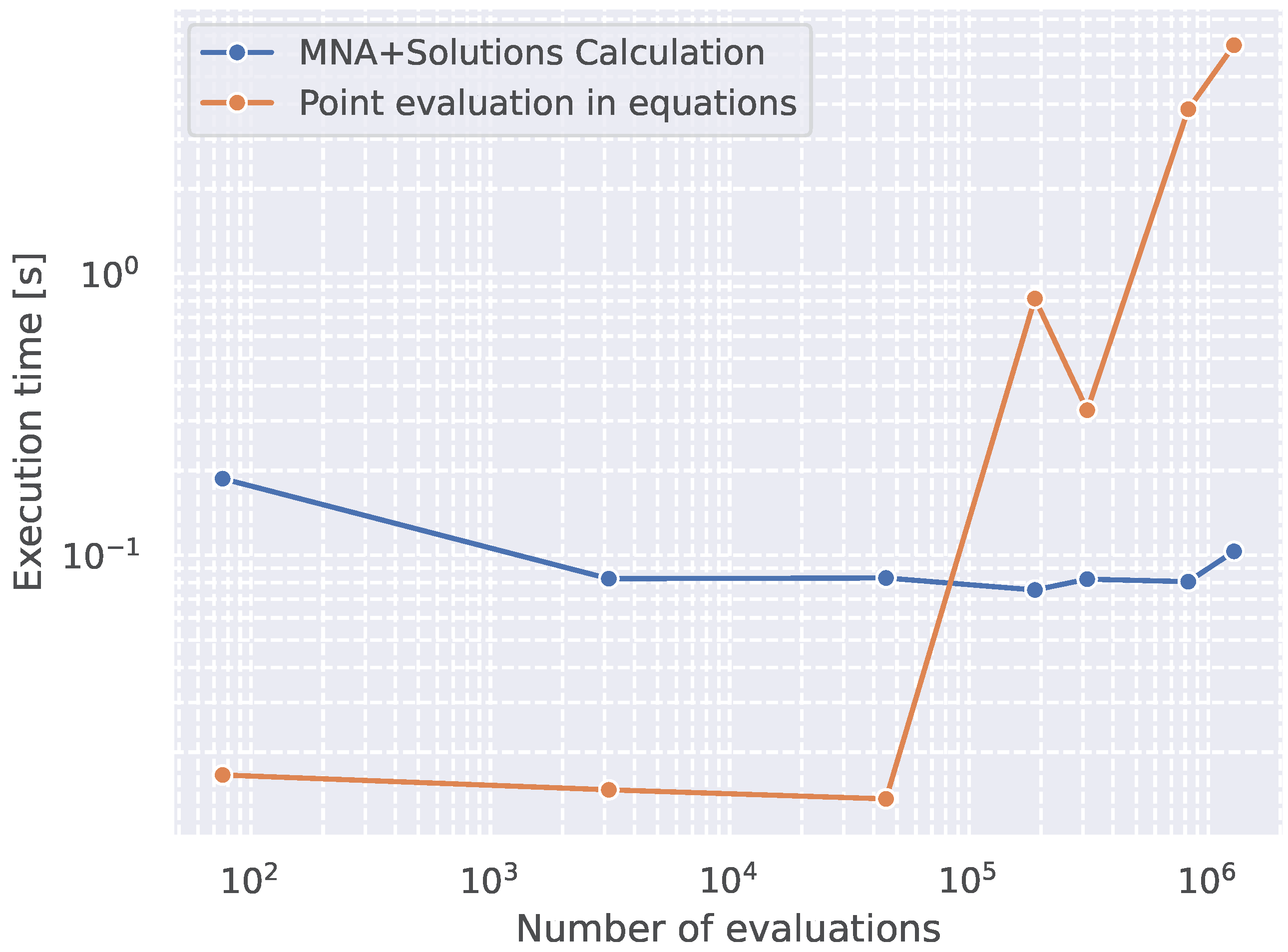
To complement this evaluation, Figure 17 shows the execution times associated with MNA and vectorized evaluation stages. The MNA resolution time remains constant regardless of the number of points, indicating that its complexity depends solely on the circuit topology. In contrast, the evaluation time grows linearly with the number of configurations. This underscores the importance of reducing the number of design points early in the process, which the proposed hierarchical exploration inherently achieves.
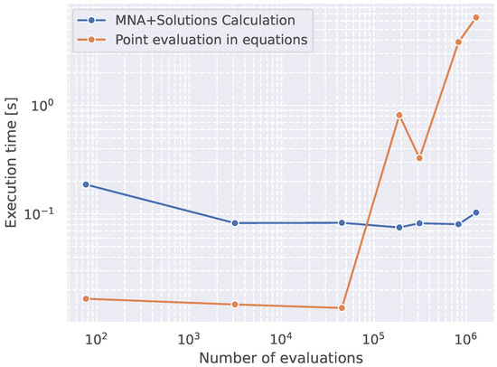
Figure 17.
Timing results of the methodology implementation.
For benchmarking purposes, an attempt was made to symbolically resolve the topology used in [12]. Unlike the current methodology, that design does not simplify the circuit before analysis, which significantly increases symbolic complexity. In multiple trials, the symbolic solver failed to produce results within two hours. This suggests the use of high-performance computing resources or alternative methods in that reference, whereas the approach proposed in this work remained efficient using standard open-source tools.
Numerically, both methods achieve comparable throughput during LUT evaluation. However, the number of degrees of freedom plays a critical role; in unsimplified or monolithic topologies, the exponential growth of design points drastically affects runtime. This emphasizes the importance of symbolic simplification and hierarchical modularization as core enablers of scalable analog design automation.
In summary, this work presented a systematic and structured methodology for the automation of transistor-level design in analog circuits, validated through the implementation of LDO regulators across three topologies and three open-source technologies. By combining hierarchical modeling, symbolic analysis, and LUT-based exploration, the methodology enables specification-driven design while avoiding the need for iterative simulations. It allows for module reuse, early pruning of infeasible solutions, and fine-grained control over design complexity.
This framework provides a solid and extensible foundation for scalable analog design automation, and opens the door for future extensions such as layout integration, broader circuit classes, and the incorporation of machine learning to assist in exploration and decision making.
Author Contributions
Conceptualization, D.A., J.M. and C.A.R.; software, D.A. and K.H.; formal analysis, D.A.; investigation, D.A., J.M., K.H. and C.A.R.; resources, C.A.R., J.M., K.H., J.G. and S.W.; writing—original draft preparation, D.A., J.M., C.A.R. and J.G.; writing—review and editing, C.A.R., J.M., J.G., K.H. and S.W.; visualization, D.A., J.M. and S.W.; supervision, C.A.R. and J.M.; project administration, C.A.R., J.M. and K.H.; funding acquisition, C.A.R., J.M., K.H., J.G. and S.W. All authors have read and agreed to the published version of the manuscript.
Funding
This research was funded by AC3E (ANID/BASAL/AFB240002), by ANID + Fondecyt de Exploración 2025 + 13250147, by ANID + FONDECYT Initiation Research Project 11240947, by ANID + FONDECYT Regular Project 1240537, by ANID/FONDAP/1522A0006.
Data Availability Statement
The original contributions presented in the study are included in the article; further inquiries can be directed to the corresponding author.
Conflicts of Interest
The authors declare no conflict of interest.
References
- Gray, P.R.; Hurst, P.J.; Lewis, S.H.; Meyer, R.G. Analysis and Design of Analog Integrated Circuits; John Wiley & Sons: Hoboken, NJ, USA, 2024. [Google Scholar]
- Gielen, G.G.; Hernandez, L.; Rombouts, P. Time-Encoding Analog-to-Digital Converters: Bridging the Analog Gap to Advanced Digital CMOS-Part 1: Basic Principles. IEEE Solid-State Circuits Mag. 2020, 12, 47–55. [Google Scholar] [CrossRef]
- Linán-Cembrano, G.; Lourenço, N.; Horta, N.; de la Rosa, J.M. Design Automation of Analog and Mixed-Signal Circuits Using Neural Networks—A Tutorial Brief. IEEE Trans. Circuits Syst. II Express Briefs 2024, 71, 1677–1682. [Google Scholar] [CrossRef]
- Scheible, J. Optimized is Not Always Optimal - The Dilemma of Analog Design Automation. In Proceedings of the 2022 International Symposium on Physical Design, ISPD ’22, New York, NY, USA, 27–30 March 2022; pp. 151–158. [Google Scholar] [CrossRef]
- Toledo, P.; Rubino, R.; Musolino, F.; Crovetti, P. Re-Thinking Analog Integrated Circuits in Digital Terms: A New Design Concept for the IoT Era. IEEE Trans. Circuits Syst. II Express Briefs 2021, 68, 816–822. [Google Scholar] [CrossRef]
- Chen, H.; Liu, M.; Tang, X.; Zhu, K.; Sun, N.; Pan, D.Z. Challenges and opportunities toward fully automated analog layout design. J. Semicond. 2020, 41, 111407. [Google Scholar] [CrossRef]
- Marin, J.; Arevalos, D.; Cortes, A.; Osorio, V.; Romero, M.; Gak, J.; Calarco, N.; Miguez, M.; Tork, A.; Mahmoud, M.; et al. Design and automated layout generation of a pmic core in skywater 130nm open-source technology. In Proceedings of the 2024 IEEE 15th Latin America Symposium on Circuits and Systems (LASCAS), Punta del Este, Uruguay, 27 February–1 March 2024; pp. 1–5. [Google Scholar]
- Razavi, B. The Low Dropout Regulator [A Circuit for All Seasons]. IEEE Solid-State Circuits Mag. 2019, 11, 8–13. [Google Scholar] [CrossRef]
- Sobhan Bhuiyan, M.A.; Hossain, M.R.; Minhad, K.N.; Haque, F.; Hemel, M.S.K.; Md Dawi, O.; Ibne Reaz, M.B.; Ooi, K.J.A. CMOS Low-Dropout Voltage Regulator Design Trends: An Overview. Electronics 2022, 11, 193. [Google Scholar] [CrossRef]
- Fayazi, M.; Colter, Z.; Afshari, E.; Dreslinski, R. Applications of Artificial Intelligence on the Modeling and Optimization for Analog and Mixed-Signal Circuits: A Review. IEEE Trans. Circuits Syst. I Regul. Pap. 2021, 68, 2418–2431. [Google Scholar] [CrossRef]
- Budak, A.F.; Gandara, M.; Shi, W.; Pan, D.Z.; Sun, N.; Liu, B. An Efficient Analog Circuit Sizing Method Based on Machine Learning Assisted Global Optimization. IEEE Trans.-Comput.-Aided Des. Integr. Circuits Syst. 2022, 41, 1209–1221. [Google Scholar] [CrossRef]
- Mohamed, K.; Nafea, S.; Omran, H. Design Automation of Low Dropout Voltage Regulators: A General Approach. Electronics 2022, 12, 205. [Google Scholar] [CrossRef]
- Ho, C.W.; Ruehli, A.; Brennan, P. The modified nodal approach to network analysis. IEEE Trans. Circuits Syst. 1975, 22, 504–509. [Google Scholar] [CrossRef]
- Youssef, A.A.; Murmann, B.; Omran, H. Analog IC design using precomputed lookup tables: Challenges and solutions. IEEE Access 2020, 8, 134640–134652. [Google Scholar] [CrossRef]
- Arevalos, D.; Marín, J.; Herman, K.; Rojas, C.A. Leveraging Lookup Tables for Efficient LDO Design Exploration using Open-Source CAD Tools and IHP-Open130-G2 PDK. In Proceedings of the 2024 31st International Conference on Mixed Design of Integrated Circuits and System (MIXDES), Gdansk, Poland, 27–28 June 2024; pp. 124–129. [Google Scholar] [CrossRef]
- SkyWater Technology. SKY130 Open Source PDK. Available online: https://www.skywatertechnology.com/sky130-open-source-pdk/ (accessed on 30 April 2025).
- GlobalFoundries. GF180MCU Open Source PDK Documentation. Available online: https://gf180mcu-pdk.readthedocs.io/ (accessed on 30 April 2025).
- IHP Microelectronics. Open Source PDK. Available online: https://www.ihp-microelectronics.com/services/research-and-prototyping-service/fast-design-enablement/open-source-pdk (accessed on 30 April 2025).
- Stefanovic, D.; Kayal, M. Structured Analog CMOS Design; Springer Science & Business Media: Berlin, Germany, 2008. [Google Scholar]
- Abel, I.; Neuner, M.; Graeb, H.E. A Hierarchical Performance Equation Library for Basic Op-Amp Design. IEEE Trans.-Comput.-Aided Des. Integr. Circuits Syst. 2022, 41, 1976–1989. [Google Scholar] [CrossRef]
- Long, Z.; Li, L.; Han, L.; Meng, X.; Ding, C.; Li, R.; Jiang, W.; Ding, F.; Yue, J.; Li, Z.; et al. Computational Graph Representation of Equations System Constructors in Hierarchical Circuit Simulation. arXiv 2024, arXiv:2407.04206. [Google Scholar] [CrossRef]
- Jespers, P.G.A.; Murmann, B. Systematic Design of Analog CMOS Circuits: Using Pre-Computed Lookup Tables, 1st ed.; Cambridge University Press: Cambridge, UK, 2017. [Google Scholar] [CrossRef]
- Cormen, T.H.; Leiserson, C.E.; Rivest, R.L.; Stein, C. Chapter 22, Section 22.3: Depth-First Search. In Introduction to Algorithms, 3rd ed.; MIT Press: Cambridge, MA, USA, 2009. [Google Scholar]
- Razavi, B. The Design of An LDO Regulator [The Analog Mind]. IEEE Solid-State Circuits Mag. 2022, 14, 7–17. [Google Scholar] [CrossRef]
- Dinesh Shylaja, A.; Rincón-Mora, G.A. High-PSR LDOs: Variations, Improvements, and Best Compromise. IEEE Trans. Circuits Syst. II Express Briefs 2022, 69, 924–928. [Google Scholar] [CrossRef]
- Zachos, N.; Gogolou, V.; Noulis, T. A Fully Integrated 1.8 V Low-Power LDO Regulator with Dynamic Transient Control for SoC Applications. Electronics 2024, 13, 4734. [Google Scholar] [CrossRef]
- Chen, C.; Sun, M.; Wang, L.; Huang, T.; Xu, M. A Fast Transient Response Capacitor-Less LDO with Transient Enhancement Technology. Micromachines 2024, 15, 299. [Google Scholar] [CrossRef] [PubMed]
- Arizmendi, C.F.V. A 0.18 μm Cmos Internally-Compensated Low-Dropout Voltage Regulator; National Institute for Astrophysics, Optics and Electronics Tonantzintla: Puebla, Mexico, 2014. [Google Scholar]
- Li, Z.; Carusone, A.C. Design and Optimization of Low-Dropout Voltage Regulator Using Relational Graph Neural Network and Reinforcement Learning in Open-Source SKY130 Process. In Proceedings of the 2023 IEEE/ACM International Conference on Computer Aided Design (ICCAD), San Francisco, CA, USA, 28 October–2 November 2023; pp. 1–9. [Google Scholar] [CrossRef]
- Cherivirala, Y.K.; Saligane, M.; Wentzloff, D.D. An Open Source Compatible Framework to Fully Autonomous Digital LDO Generation. In Proceedings of the 2023 IEEE International Symposium on Circuits and Systems (ISCAS), Monterey, CA, USA, 21–25 May 2023; pp. 1–5. [Google Scholar] [CrossRef]
Disclaimer/Publisher’s Note: The statements, opinions and data contained in all publications are solely those of the individual author(s) and contributor(s) and not of MDPI and/or the editor(s). MDPI and/or the editor(s) disclaim responsibility for any injury to people or property resulting from any ideas, methods, instructions or products referred to in the content. |
© 2025 by the authors. Licensee MDPI, Basel, Switzerland. This article is an open access article distributed under the terms and conditions of the Creative Commons Attribution (CC BY) license (https://creativecommons.org/licenses/by/4.0/).

