Abstract
This paper presents the first hybrid supply modulator (HSM) designed for envelope tracking power amplifiers (ET-PAs) in base station applications. The focus is on a rail-to-rail Class-AB linear amplifier (LA) optimized for high-voltage and wide-bandwidth operation. The LA is designed using 130 nm BCD technology, utilizing Laterally Diffused Metal-Oxide Semiconductor (LDMOS) transistors for high-voltage operation and incorporating shielding MOSFETs to protect the low-voltage devices. The circuit utilizes dual power supply domains (5 V and 30 V) to improve power efficiency. The proposed LA achieves a bandwidth of 100 MHz and a slew rate of +1003/−852 V/, with a quiescent power consumption of 0.89 W. Transient simulations using a 50 MHz bandwidth 5G NR envelope input demonstrate that the proposed HSM achieves a power efficiency of 83%. Consequently, the proposed HSM supports high-output (100 W) wideband 5G NR transmission with enhanced efficiency.
1. Introduction
High peak-to-average power ratio (PAPR) and wideband signals in 5G systems demand power amplifiers (PAs) with improved efficiency [,]. In user equipment (UE), envelope tracking (ET) has been widely adopted to enhance PA efficiency while maintaining linearity [,,,,,,,,,,,].
While efficiency improvements in base station PAs have been achieved using Doherty amplifiers [,], research on the ET technique for base stations remains limited. As shown in Table 1, unlike UE, base station PAs require high output power and supply voltage operation. Considering the peak power and efficiency of the PA, the supply modulator (SM) must be capable of delivering peak output power exceeding 100 W to meet these demands. To address this, this work proposes a hybrid supply modulator (HSM) with a high-voltage linear amplifier (LA) based on Laterally Diffused Metal-Oxide Semiconductor (LDMOS) transistors. Integrated LDMOS-based SM reduces PCB-induced parasitic impedance, enabling wideband and high-voltage operation. LDMOS transistors provide high drain-to-source breakdown voltages (10–48 V) but have gate-to-source breakdown voltage limits below 5 V and significantly larger parasitic capacitance than CMOS transistors, which can limit speed and stability. Therefore, ensuring fast charging and discharging is critical for wideband ET.

Table 1.
Summary of commercial base station power amplifier key performance.
This work presents a rail-to-rail Class-AB LA that satisfies the high voltage, fast transient, and wideband requirements of HSM for efficient 5G base station transmission. To enhance efficiency, the LA uses separate low-voltage (LV) and high-voltage (HV) domains. In Section 2, the output power range requirements and the topology of the proposed HSM for the base station PA are discussed. The design of the proposed wideband LA is also described in detail in the same section. In Section 3, the simulation results and performance evaluation of the proposed circuit are presented. Finally, Section 4 concludes this work.
2. HSM for Base Station PA
2.1. HSM Output Power Requirement
To design HSM, it is essential to understand the performance characteristics of the target PA. Figure 1 presents the performance of the TGA2307-SM PA for base station applications. In Figure 1a, the saturated output power () reaches 47 dBm. In Figure 1b, the corresponding drain current at is approximately 4 A. Given a fixed supply voltage of 28 V, the SM must deliver up to 112 W.
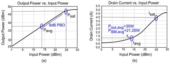
Figure 1.
Performance of the base station PA (TGA2307-SM): (a) output power vs. input power; (b) drain current vs. input power [].
For high linearity operation, the PA typically operates under power back-off (PBO). At 9 dB PBO, which corresponds to the average output power condition, Figure 1b shows that the drain current () is 1.25 A. In (1), under a fixed supply operation at 28 V, the average supply power () becomes 35 W. In (2), when operating with ET, the rms supply voltage () is reduced to 17 V. Assuming the rms SM current () is approximately equal to the , the average supply power () becomes 21.25 W. In (3), based on these values, the power saving compared to fixed supply operation is calculated as ≈ 39.3%. In (4), the SM must maintain the supply voltage above the knee voltage () to ensure proper PA operation. Table 2 summarizes the target SM output power, voltage, and current based on the operating region of the TGA2307-SM PA.

Table 2.
Target SM output power, voltage, and current performance.
2.2. HSM Topology
Figure 2 illustrates the topology of the proposed HSM, which consists of a wideband LA and a high-efficiency Switching Amplifier (SA).
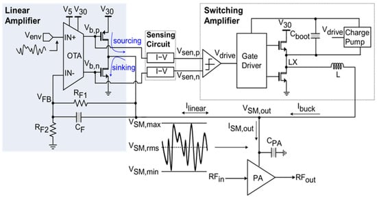
Figure 2.
HSM topology.
Figure 3 illustrates the operation of HSM. In the simulation shown in Figure 3, the PA was modeled as an equivalent resistance of 8 Ω for simplicity. To simplify the PA model, a decoupling capacitor () of 200 pF and an equivalent resistance () of 8 Ω were used. Although the PAs exhibit nonlinear impedance characteristics, such complexity is impractical for circuit-level simulations. Thus, a simplified resistive model was adopted. The selected resistance value was based on the target PA, TGA2307-SM, which specifies , and , corresponding to = = 13.6 Ω. To ensure sufficient drive strength and test under more demanding conditions, a lower resistance of 8 Ω was chosen.
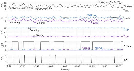
Figure 3.
HSM operation waveform.
The LA operates as a voltage source, generating an output voltage (), proportional to the input RF envelope signal () with a system gain of 15. The sensing circuit determines whether LA generates sourcing or sinking current into the PA. This block generates two sensing currents through and , which flow through sensing resistors to produce the corresponding voltages, and . These voltages serve as inputs to a hysteretic comparator, which then drives the SA. Based on the comparator output, controls the high- and low-side switches to regulate the LX node voltage and generate the SA current (). In (5), the total output current of the supply modulator () consists of the sum of the and the LA current (). The primarily supplies the low-frequency, near-DC current, while the handles the high-frequency AC current.
2.3. Linear Amplifier Design
Figure 4 shows the schematic of the proposed LA. It consists of three gain stages: the first stage is a PMOS differential pair input stage, the second stage is implemented as a mirrored operational transconductance amplifier (OTA), and the third stage adopts a rail-to-rail Class-AB output stage. A reference current source based on a bandgap reference (BGR) generates stable bias currents. The amplifier employs a feedback network of , , and to define the feedback factor and ensure loop stability.
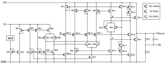
Figure 4.
Proposed LA schematic.
2.3.1. LA Power Efficiency
In HSM applications, the LA provides wide bandwidth but suffers from low power efficiency. The efficiency decreases when the LA operates under a single high-voltage supply. The proposed LA improves power efficiency through a dual supply voltage domain architecture. The reference current source and first stage operate in a 5 V LV domain. The second and third stages, which drive large output swings, utilize a 30 V HV domain.
2.3.2. Shielding MOSFETs
MN10–MN12, MN19, and MP10 function as shielding MOSFETs, which block overvoltage from reaching the LV domain transistors. These MOSFETs also operate in a common-gate configuration, allowing high-voltage domain signals to be interfaced with lower-voltage blocks. MP10 is implemented as a PMOS transistor to ensure proper signal transmission. When configured as a common-gate device, a PMOS allows input signals to be applied at the source and propagated toward the drain, which is suitable for transferring signal variations.
2.3.3. Frequency Response of LA
Modern communication signals have wide bandwidths, requiring an LA with a wide bandwidth for accurate envelope tracking. Typically, the LA bandwidth must be 1.5 to 3 times larger than the envelope signal bandwidth to maintain sufficient tracking accuracy in HSM []. In the proposed design, two factors mainly limit the LA bandwidth. First, the floating current source introduces output impedance at nodes X and Y, connected to the gate of the PMOS and NMOS output transistors, respectively. Figure 5 illustrates the small-signal test setup used to analyze the impedance seen from node X of the floating current source.
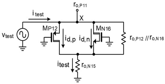
Figure 5.
Small-signal impedance of the floating current source at node X [].
By applying a test voltage , a current flows through the network. The small-signal drain currents and flow through MP12 and MN16, respectively, and the remaining current flows through the parallel output resistances . From this configuration, the node voltage is given in (6), and the drain currents and are defined in (7) and (8), respectively. Inserting (7) and (8) into (6) gives (9), which simplifies (9a). The resistance of the floating current source seen from node X is given in (10) and further simplified to (10a) when =
The resistance at node X is approximately and a large gate capacitance (~100 pF) is also present. Therefore, a dominant pole appears at node X, as shown in (11). Similarly, the pole at node Y is given in (12). The dominant pole of the system is determined by the lower frequency between the poles at nodes X and Y.
A second pole appears at the output. It is determined by the output impedance of the LA (), the PA equivalent resistance (), and a decoupling capacitance (), as shown in Figure 6. The is determined by the parallel combination of the output resistances of transistors and . It can be expressed as . When , the output pole can be approximated as shown in (13). In this design, and , placing the second pole around .
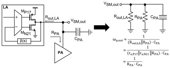
Figure 6.
Simplified modeling of the SM output pole.
The LA system contains two internal poles, along with an additional pole near the unity-gain bandwidth (UGBW), which may affect overall stability. To address this, a zero is introduced in the feedback path, as shown in Figure 7. The frequency-dependent feedback factor is expressed in (14) and is simplified in (14a) and (14b), where the resulting zero and pole are given in (15) and (16), respectively. With , , the zero and pole are located at and , as illustrated in Figure 8.
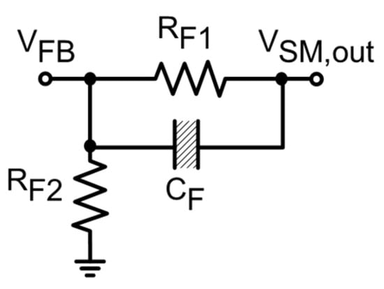
Figure 7.
Feedback path analysis [].
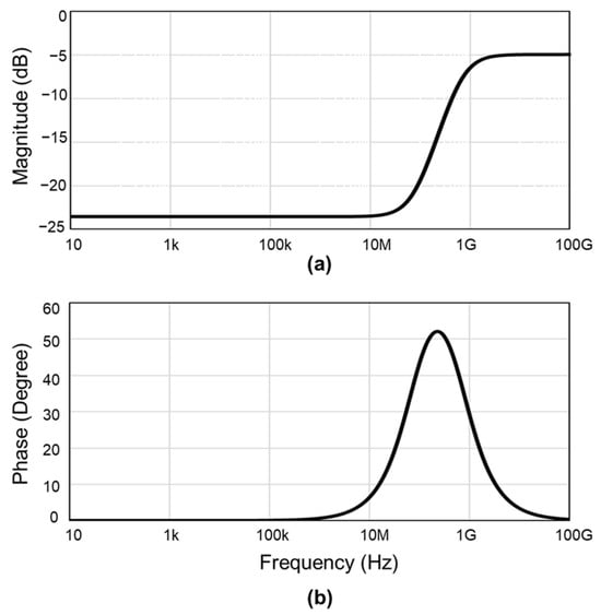
Figure 8.
Frequency response of feedback path: (a) magnitude; (b) phase.
Figure 9 shows the frequency response of the LA for different common-mode levels of (Min: 400 mV, Typical: 1.13 V, and Max: 1.86 V). The plots include both the loop gain and phase response of the LA. Owing to the feedback path, both the loop UGBW and phase margin (PM) are improved. The UGBW increases from 76 MHz to a maximum of 128 MHz, while the PM improves from 22.6° to 56°. At = 1.13 V, which corresponds to the Class-AB crossover point, the total transconductance of the output power transistors decreases, resulting in a reduced LA loop gain. The UGBW remains above 100 MHz across the remaining range from 400 mV to 1.86 V.
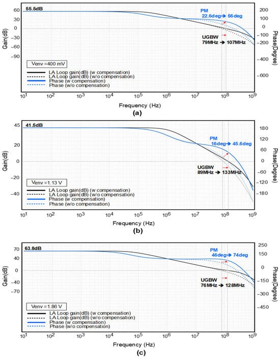
Figure 9.
Loop gain and phase of the LA with and without compensation: (a) ; (b) ; (c) .
2.3.4. Slew Rate of LA
In [,], to accurately track high PAPR signals, the LA must provide not only wideband characteristics but also a high slew rate. As shown in Figure 10, nodes X and Y are the most critical nodes affecting the slew rate. The total capacitance at node X is dominated by the gate capacitance of MP17, while that of node Y is primarily determined by the gate capacitance of MN21. The output power transistors (MP17 and MN21) are sized large to handle output currents up to 2.5 A. Consequently, their gate capacitance becomes significant, consisting of both intrinsic capacitance (~100 pF) and additional parasitic capacitance from layout effects. To maintain high slew rate performance, these gate capacitances must be rapidly charged and discharged. Figure 11 compares the slew rate performance under sufficient and insufficient floating current source conditions. A 20 MHz envelope signal with a 1.13 V offset and 730 mV amplitude is applied, requiring the output voltage to swing from 6 V to 28 V. The results show that insufficient source current limits the gate charging speed, degrading the slew rate and impairing envelope tracking accuracy. To improve the slew rate, sufficient current must be provided to quickly charge and discharge the gate capacitance of the output power transistors, as defined by the relation Slew Rate = I/C. As illustrated in Figure 10, the tail current source was increased to 1.5 mA to enhance the available current for charging and discharging. In addition, the current mirror ratios for (MP8, MP11) and (MP7, MP9) were configured to 1:10, ensuring that the charging/discharging current at nodes X and Y is amplified accordingly to effectively drive the large gate capacitances of MP17 and MN21.
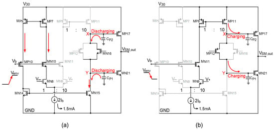
Figure 10.
Slew rate by charging and discharging Class-AB output stage gate capacitance: (a) rising edges; (b) falling edges.
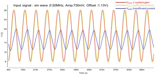
Figure 11.
Comparison of slew rate under sufficient and insufficient current conditions.
Figure 12 shows the transient response when a 50 MHz envelope signal with a 1.13 V offset and 340 mV amplitude is applied, resulting in a smaller output swing from 12 V to 22 V. Unlike the 20 MHz case, full swing from 6 V to 28 V is not achieved due to the higher slew rate requirement. Although a 50 MHz sine wave input requires a higher slew rate for accurate tracking, the actual 50 MHz envelope signal used in this work has its power spectral density mainly concentrated below 50 MHz. This implies that the measured slew rate is sufficient for tracking such practical envelope signals without distortion.
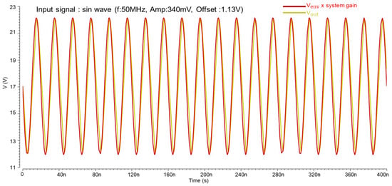
Figure 12.
Transient waveforms of and × system gain in response to a 50 MHz sine wave input.
The maximum slew rate performance was evaluated by applying an input pulse to the LA input, with a 2.125 A DC current source connected at the output node to substitute for , which primarily supplies the near-DC current component in HSM operation. The was driven to swing from 6 V to 28 V and from 28 V to 6 V, and the corresponding slew rates, calculated from the dV/dt of these transitions, were measured as a +1003/−852 V/, respectively.
3. Simulation Results
The proposed ET HSM was designed using a 130 nm BCD process, occupying a chip area of 6.36 mm2. Figure 13 shows the chip layout of the proposed LA. Figure 14a presents the transient simulation results for a 50 MHz envelope input and the corresponding output voltage. Figure 14b illustrates the current waveforms of LA, SA, and the overall output. The HSM achieves a simulated power efficiency of 83%. Table 3 summarizes the performance metrics of the proposed HSM and provides a comparison with previously reported works.
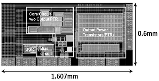
Figure 13.
Chip layout of the proposed LA.
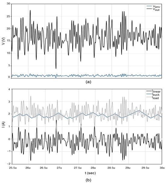
Figure 14.
Transient simulation results of ET HSM for 50 MHz envelope signal : (a) input and output voltage waveforms; (b) current of LA , SA , output .

Table 3.
Comparison table.
This work is the first to implement HSM for base station PA applications, which require a wide output voltage range, 6 V to 28 V, and high output power. To meet these requirements, we employed LDMOS devices in a 130 nm BCDMOS process. Unlike conventional CMOS used in previous UE PA applications, LDMOS transistors include a drift region to support high-voltage operation, which increases the device parasitic capacitance and degrades bandwidth performance. Despite the bandwidth limitations of LDMOS, the proposed HSM successfully tracks a 50 MHz signal bandwidth.
While the efficiency is slightly lower than in previous low-voltage domains [,,], this is mainly due to the higher supply voltage, 30 V, used in this work. Since power loss increases with higher supply voltage (P = V × I), achieving high efficiency becomes more challenging in high-voltage domains.
4. Conclusions
This work presents the first implementation of a 30 V rail-to-rail Class-AB buffer amplifier for ET-PA HSM. Using LDMOS transistors, the proposed HSM achieves a high output voltage swing of 6–28 V, suitable for high-power base station PAs. To enhance LA power efficiency, the design adopts dual supply rails of 5 V and 30 V. Incorporating an LA with a 100 MHz 3 dB bandwidth, the HSM successfully tracks a 50 MHz envelope signal and achieves a power efficiency of 83%.
Author Contributions
Conceptualization, M.-J.K. and D.K.; Writing—original draft preparation, M.-J.K.; Writing—review and editing, D.K., G.C., S.-J.Y. and J.-S.P.; Visualization, M.-J.K., D.K., G.C. and S.-J.Y.; Supervision, J.-S.P. All authors have read and agreed to the published version of the manuscript.
Funding
This work was supported by 2025 Specialization Project of Pusan National University. This work was supported by the Korea Institute for Advancement of Technology (KIAT) grant funded by the Korea Government (MOTIE) (RS-2025-02214408, HRD Program for Industrial Innovation).
Data Availability Statement
Data are contained within the article.
Conflicts of Interest
The author declares no conflicts of interest.
References
- Paek, J.-S. Analysis and Design of Low-Noise Radio-Frequency Power Amplifier Supply Modulator for Frequency Division Duplex Cellular Systems. Electronics 2024, 13, 4635. [Google Scholar] [CrossRef]
- Paek, J.-S. n77 Radio Frequency Power Amplifier Module for 5G New-Radio High-Power User Equipment Mobile Handset Applications. Electronics 2024, 13, 908. [Google Scholar] [CrossRef]
- Liu, X.; Jiang, J.; Huang, C.; Mok, P.K.T. Design Techniques for High-Efficiency Envelope-Tracking Supply Modulator for 5th Generation Communication. IEEE Trans. Circuits Syst. II Exp. Briefs 2022, 69, 2586–2591. [Google Scholar] [CrossRef]
- Zhang, K.; Wu, J.; Zhuang, H.; Shi, Z.; Lyu, X.; Wang, Z.; Chen, H.; Yu, F. A Wideband Hybrid Envelope Tracking Supply Modulator with Slew-Rate-Enhanced Linear Amplifier. Electronics 2024, 13, 2701. [Google Scholar] [CrossRef]
- He, H.; Kang, Y.; Ge, T.; Guo, L.; Chang, J.S. A 2.5-W 40-MHz-Bandwidth Hybrid Supply Modulator with 91% Peak Efficiency, 3-V Output Swing, and 4-mV Output Ripple at 3.6-V Supply. IEEE Trans. Power Electron. 2019, 34, 712–723. [Google Scholar] [CrossRef]
- Xu, P.; Xia, Y.; Wang, Z.; Yang, J.; Guo, L.; Wang, Y.; Li, Y.; Wu, Y. A 2.7 W AC-coupled hybrid supply modulator achieving 200 MHz envelope-tracking bandwidth for 5G new radio power amplifier. In Proceedings of the IEEE Asian Solid-State Circuits Conference (A-SSCC), Busan, Republic of Korea, 8–10 November 2021; pp. 1–3. [Google Scholar]
- Mahmoudidaryan, P.; Mandal, D.; Bakkaloglu, B.; Kiaei, S. Wideband Hybrid Envelope Tracking Modulator with Hysteretic-Controlled Three-Level Switching Converter and Slew-Rate Enhanced Linear Amplifier. IEEE J. Solid-State Circuits 2019, 54, 3336–3347. [Google Scholar] [CrossRef]
- Kim, J.; Park, J.; Moon, J.; Woo, J.; Lee, B. Highly Efficient RF Transmitter over Broad Average Power Range Using Multilevel Envelope-Tracking Power Amplifier. IEEE Trans. Circuits Syst. I Regul. Pap. 2015, 62, 1648–1657. [Google Scholar] [CrossRef]
- Oh, H.; Kim, D.; Park, S.; Kim, J.; Lee, H. Hybrid ET Supply Modulator IC with an Adaptive Quiescent Current Controller for Its Linear Amplifier. In Proceedings of the 2021 IEEE MTT-S International Microwave Symposium (IMS), Atlanta, GA, USA, 7–10 June 2021; pp. 649–652. [Google Scholar]
- Tan, M.; Ki, W.-H. An Efficiency-Enhanced Hybrid Supply Modulator with Single-Capacitor Current-Integration Control. IEEE J. Solid-State Circuits 2016, 51, 533–542. [Google Scholar]
- Shrestha, R.; van der Zee, R.; de Graauw, A.; Nauta, B. A Wideband Supply Modulator for 20 MHz RF Bandwidth Polar PAs in 65 nm CMOS. IEEE J. Solid-State Circuits 2009, 44, 1272–1280. [Google Scholar] [CrossRef]
- Wu, P.Y.; Mok, P.K.T. A Two-Phase Switching Hybrid Supply Modulator for RF Power Amplifiers With 9% Efficiency Improvement. IEEE J. Solid-State Circuits 2010, 45, 2543–2556. [Google Scholar] [CrossRef]
- Chen, Z.; Xu, P.; Yang, S.; Yan, J.; Luo, Z.; Ki, W.H. An Open Loop Digitally Controlled Hybrid Supply Modulator Achieving High Efficiency for Envelope Tracking with Baseband up to 200 MHz. IEEE Trans. Circuits Syst. I Regul. Pap. 2020, 67, 4142–4153. [Google Scholar] [CrossRef]
- Lin, Y.-C.; Chen, Y.-J.E. A CMOS Envelope Tracking Supply Converter for RF Power Amplifiers of 5G NR Mobile Terminals. IEEE Trans. Power Electron. 2021, 36, 6814–6823. [Google Scholar] [CrossRef]
- Xiao, M.; Zhang, W. A Design and Implementation of High-Efficiency Asymmetric Doherty Radio Frequency Power Amplifier for 5G Base Station Applications. Electronics 2025, 14, 1586. [Google Scholar] [CrossRef]
- Wang, F.; Wang, H. A High-Power Broadband Multi-Primary DAT-Based Doherty Power Amplifier for mm-Wave 5G Applications. IEEE J. Solid-State Circuits 2021, 56, 1668–1681. [Google Scholar] [CrossRef]
- Qorvo. TGA2307-SM Datasheet. Available online: https://www.qorvo.com/products/d/da003980 (accessed on 19 May 2025).
- Bhardwaj, S.; Moallemi, S.; Kitchen, J. A Review of Hybrid Supply Modulators in CMOS Technologies for Envelope Tracking PAs. IEEE Trans. Power Electron. 2023, 38, 6036–6062. [Google Scholar] [CrossRef]
- Baker, R.J. CMOS: Circuit Design, Layout, and Simulation, 3rd ed.; Wiley-IEEE Press: Hoboken, NJ, USA, 2010; pp. 703–704. [Google Scholar]
- Kim, D.; Kang, D.; Kim, J.; Cho, Y.; Kim, B. Wideband Envelope Tracking Power Amplifier for LTE Application. In Proceedings of the 2012 IEEE Radio Frequency Integrated Circuits Symposium (RFIC), Montreal, QC, Canada, 17–19 June 2012; pp. 275–278. [Google Scholar]
- Mahmoudidaryan, P.; Mandal, D.; Bakkaloglu, B.; Kiaei, S. 27.5 A 91%-Efficiency Envelope-Tracking Modulator Using Hysteresis-Controlled Three-Level Switching Regulator and Slew-Rate-Enhanced Linear Amplifier for LTE-80MHz Applications. In Proceedings of the 2019 IEEE International Solid-State Circuits Conference (ISSCC), San Francisco, CA, USA, 17–21 February 2019; pp. 428–430. [Google Scholar]
- Zhang, M.; Wang, X.; Liu, H.; Qi, X.; Li, X.; Wang, S. Class-AB Operational Amplifier with Current Domain Slew-Rate Enhancement. In Proceedings of the 2022 IEEE 5th International Conference on Electronics Technology (ICET), Chengdu, China, 13–16 May 2022; pp. 142–146. [Google Scholar]
- Yang, K.; Leng, Y.; Chen, C.; Qiu, X.; Cui, X.; Xu, B.; Hui, M. Three-Level Hybrid Envelope Tracking Supply Modulator with High-Bandwidth Wide-Output-Swing. Appl. Sci. 2022, 12, 11352. [Google Scholar] [CrossRef]
Disclaimer/Publisher’s Note: The statements, opinions and data contained in all publications are solely those of the individual author(s) and contributor(s) and not of MDPI and/or the editor(s). MDPI and/or the editor(s) disclaim responsibility for any injury to people or property resulting from any ideas, methods, instructions or products referred to in the content. |
© 2025 by the authors. Licensee MDPI, Basel, Switzerland. This article is an open access article distributed under the terms and conditions of the Creative Commons Attribution (CC BY) license (https://creativecommons.org/licenses/by/4.0/).