1. Introduction
With the continuous advancement of vehicle speed and ride comfort requirements, active suspension systems are playing an increasingly critical role in suppressing body vibrations and improving handling stability and ride quality. Although traditional active suspensions based on pneumatic or hydraulic actuators have demonstrated certain improvements in vehicle dynamics, they are often constrained by limited response speed, insufficient control precision, and low energy efficiency [
1,
2], making it difficult to meet the dual demands of precise posture regulation and fast response under complex driving conditions. In recent years, electromechanical active suspensions driven by linear motors have emerged as a promising solution, offering millisecond-level response time and micron-level positioning accuracy—thus overcoming key performance limitations of conventional systems [
3,
4].
Several studies have explored various aspects of linear motor-driven active suspension systems. For instance, Papagiannis et al. [
5] proposed fault-tolerant control strategies under actuator and sensor failures to improve ride comfort and system reliability. A combined torque and suspension force control scheme based on active disturbance rejection control was presented for bearing less induction motors in [
6]. Ye et al. [
7] conducted a comparative study on semi-active suspension using LQR and H
2/H
∞ multi-objective control, revealing that both methods significantly enhance ride comfort and handling, with H
2/H
∞ performing better across multiple metrics. Mohamed et al. [
8] compared passive suspensions with active suspensions controlled by PID and fuzzy logic within a quarter-car model, concluding that active systems markedly outperform passive ones, with fuzzy controllers showing the best performance. Zhang et al. [
9] proposed an adaptive neural network backstepping controller based on an extended state observer (ESO) to improve stability and comfort. Tan et al. [
10] developed a novel vertical active damping system based on electromagnetic interaction between traction and damping coils, demonstrating effective suppression of vertical and pitch motions in superconducting electrodynamic suspension systems. Shao et al. [
11] introduced a robust fuzzy H
∞ controller for hub motor-driven electric vehicle suspensions, achieving both vibration suppression and improved system robustness. Feng et al. [
12] designed and studied a linear motor actuator tailored for active suspensions in electric vehicles, with simulation results confirming its effectiveness in enhancing comfort and stability. Sun et al. [
13] employed model predictive control for accurate thrust control of linear motors and proposed a novel constrained control strategy that significantly improved thrust tracking and suspension performance. Sande et al. [
14] designed a robust electromagnetic suspension controller, validated through both simulation and bench tests. Luo et al. [
15] design a cascaded control strategy that combines active disturbance rejection control (ADRC) with a PID controller. A quarter-car model considering system uncertainties and the electrical characteristics of the VCM is established. Both simulation and experimental results demonstrate that the proposed method significantly outperforms passive suspension in terms of vibration suppression, dynamic tire load reduction, and suspension travel control. However, the study also highlights that using a VCM as the sole actuator results in high energy consumption. Moreover, recent works have also focused on energy recovery technologies using linear motor-based actuators, where electromechanical coupling models and regenerative control strategies have been developed to convert vibration energy into electrical energy, thereby improving energy efficiency [
16,
17].
However, most existing research on linear motor-based active suspensions has focused primarily on ride comfort enhancement and energy recovery. Studies and experimental investigations on dynamic ride height regulation remain limited. In addition, many of the control strategies mentioned above rely heavily on accurate suspension models, which are difficult to obtain under real-world uncertainties. Moreover, the complexity of these advanced control algorithms poses challenges for real-time implementation, given the stringent time and stability requirements of suspension systems.
To address these issues, this paper proposes a linear active disturbance rejection control (LADRC) strategy [
18] for vehicle body height regulation in active suspension systems. LADRC employs a Linear Extended State Observer (LESO) to estimate and compensate for internal and external disturbances in real time, significantly reducing the dependence on model accuracy and simplifying parameter tuning compared to traditional ADRC.
To validate the proposed method, a two-degree-of-freedom active suspension model with a linear motor actuator was first built in MATLAB/Simulink. Simulation results verified the effectiveness of the control strategy in ride height regulation. Subsequently, a high-precision experimental platform was constructed using the NI cRIO embedded system, integrating a permanent magnet synchronous linear motor, high-dynamic driver, draw-wire encoder, and acceleration sensors. Motor control and synchronized multi-source data acquisition were implemented using LabVIEW FPGA [
19,
20]. Control performance was evaluated under both sinusoidal tracking and random road excitations to assess tracking accuracy and disturbance rejection capabilities.
3. Ride Height Regulation Based on Linear Active Disturbance Rejection Control
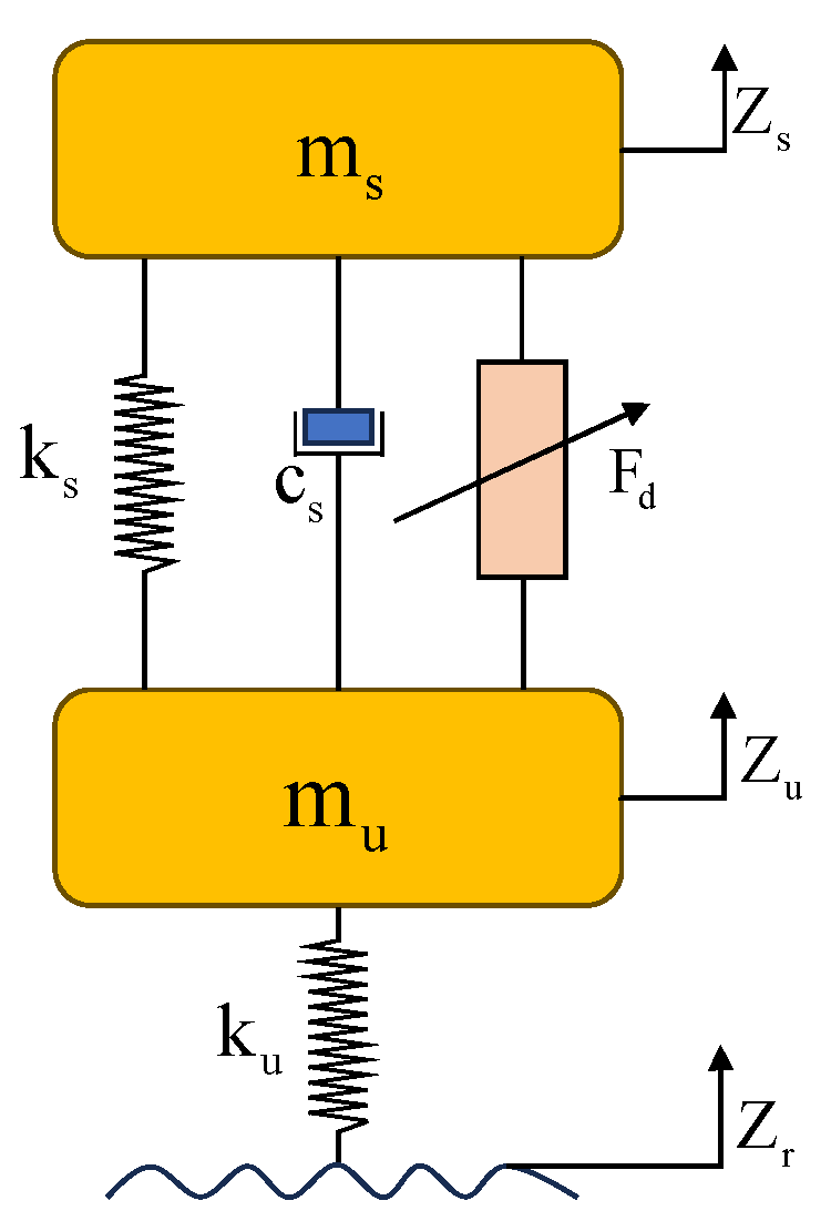
When a vehicle is in motion, the active suspension system experiences forced vertical vibrations due to road surface excitations, which significantly reduce ride comfort. Therefore, the active suspension must achieve two simultaneous objectives: suppressing body vibrations and regulating ride height.
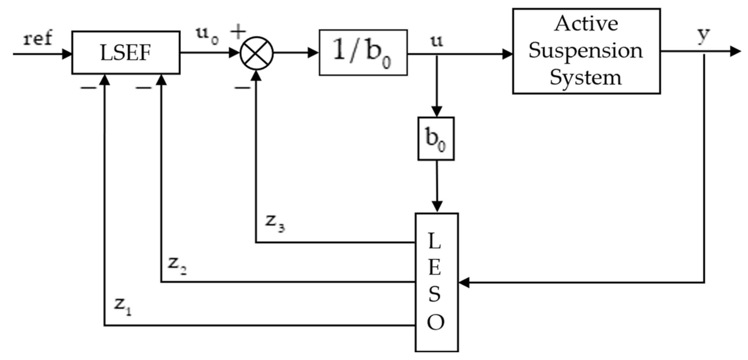
The Linear Active Disturbance Rejection Controller (LADRC) consists of three main components: a Linear Extended State Observer (LESO), a linear feedback control law, and a disturbance compensation unit. Among these, the LESO is the most critical component. It enables real-time estimation of the total disturbance acting on the system, which includes both internal disturbances due to model inaccuracies and external disturbances caused by road irregularities [
23]. The structure of the LADRC is illustrated in
Figure 2.
The goal of the control system is to minimize body vibration while maintaining the desired ride height. Accordingly, the vertical displacement of the sprung mass is selected as the system output. Since the active suspension force is generated by the linear motor, the motor thrust is selected as the control input.
The second-order system described in Equation (7) can be rewritten as
In this equation, and are system parameters, and represent the system output and control input, respectively, and denotes the external disturbance acting on the system.
Equation (1) can be reformulated as
In this expression, is the estimated value of the system parameter , and represents the total disturbance of the system, which includes both internal and external disturbances.
Let
,
, and
; the system equation can then be expressed as
In this equation, and are the system state variables, and is the extended state representing the total disturbance.
Equation (9) can be transformed into the extended state-space form as follows:
where
,
,
, and
.
The Linear Extended State Observer (LESO) is constructed as follows:
In this observer,
,
, and
denote the estimates of the system states
and
and the total disturbance
, respectively.
is the measured system output, and
,
, and
are the observer gain coefficients that determine the convergence rate of the estimates. Since the total disturbance
is unknown but can be estimated through the correction term, its derivative
is not required. Therefore, the LESO can be reformulated as
In this formulation,
represents the composite input, and
is the observer output. Through the use of a pole placement approach, the observer gains are determined by assigning the poles of the LESO to specific locations at
:
The observer gains can be selected to be , , and , where denotes the observer bandwidth.
When the state error feedback controller is able to accurately estimate the total disturbance, i.e.,
, the LADRC control law can be defined as
. Under this condition, the closed-loop system can be simplified into a cascaded integrator structure:
The linear error feedback control law is implemented in the form of a proportional–derivative (PD) controller:
where
is the desired ride height, and
and
are the controller gains. Through the substitution of Equation (15) into Equation (14), the closed-loop transfer function of the system can be obtained as
Let and , where denotes the controller bandwidth. Through the selection of an appropriate value of , the system can be ensured to be bounded-input bounded-output (BIBO)-stable.
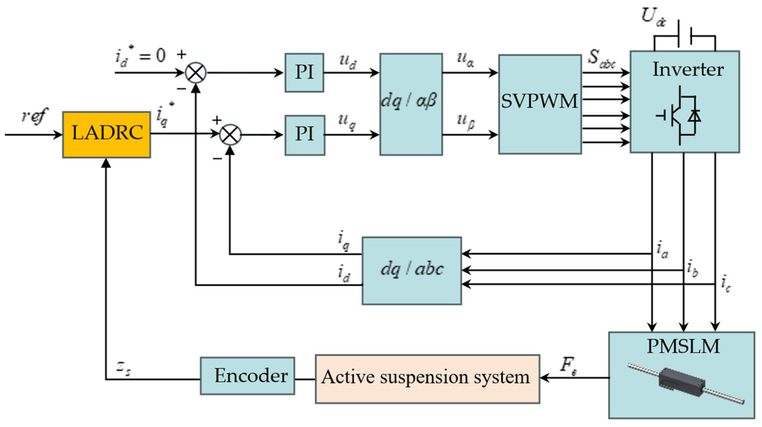
The working principle of the ride height controller is illustrated in
Figure 3. A cascaded position–current dual-loop control strategy is adopted. The outer position loop employs a Linear Active Disturbance Rejection Controller (LADRC), which calculates the force required to move the active suspension to the desired ride height based on the reference height and the measured body displacement.
The inner current loop utilizes a PI controller. The desired force output from the position loop is converted into a reference q-axis current via the thrust constant. This current reference is then used to generate three-phase voltage inputs through space vector pulse-width modulation (SVPWM), which are applied to the servo control system of the permanent magnet synchronous linear motor (PMSLM), thereby realizing precise vehicle body height adjustment.
4. Simulation and Experimental Validation
To validate the effectiveness of the linear active disturbance rejection control (LADRC) strategy for ride height regulation, a MATLAB/Simulink R2024a-based simulation model of a linear motor-driven active suspension system was developed. The model integrates the vehicle dynamics, linear motor actuator, and the dual-loop LADRC–PI control structure. The parameters of the vehicle model are as follows:
= 29 kg,
= 5.88 kg,
= 1880
,
= 19,000
, and
= 174
. The parameters of the linear motor are listed in
Table 1. The sprung mass, unsprung mass, suspension stiffness, and other vehicle-related parameters are based on the bench test platform design, while the linear motor parameters are obtained from the manufacturer’s datasheet. To ensure sufficient thrust margin during the initial design of the test bench, a relatively large linear motor was selected. The primary (mover) coil has a length of 330 mm with a base cross-section of 60 mm × 60 mm, while the secondary (stator) permanent magnet assembly measures 560 mm in length with a base diameter of 32 mm.
In order to ensure a fair and meaningful comparison with the proposed LADRC, a systematic tuning approach was adopted for the PID controller in both the simulation and experimental stages.
In the simulation phase, the PID parameters were designed using the Control System Designer toolbox in MATLAB/Simulink. The Bode plot-based pole–zero adjustment method was applied to improve system characteristics, followed by step response tests to validate the performance. After fine-tuning, a satisfactory set of parameters was obtained: , , and .
For the hardware-in-the-loop experiments, a discrete incremental-form PID controller was implemented on the LabVIEW FPGA platform. Based on the gain-tuning results from simulation, further step response tests were conducted to balance rise time and overshoot under real-world constraints. After multiple iterations, a well-optimized set of parameters was determined: , , and .
This two-stage tuning process ensures that the PID controller used in the comparison represents a realistically optimized benchmark, thereby lending credibility and reference value to the comparative evaluation with LADRC.
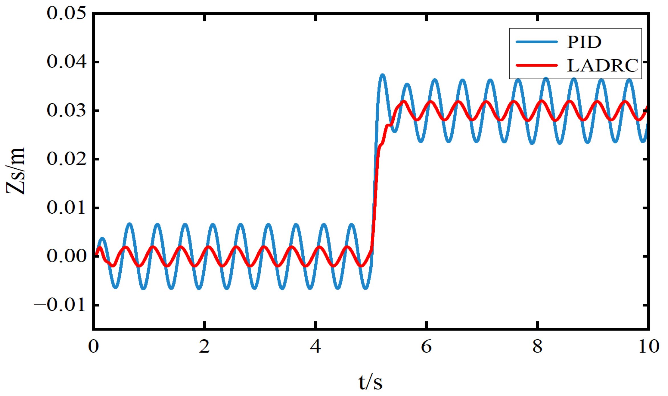
To verify the effectiveness of the proposed ride height control strategy, a sinusoidal road excitation with a frequency of 2 Hz and an amplitude of 0.01 m was applied as the input. The desired ride height was set to 0.03 m. The simulation results are presented in
Figure 4,
Figure 5 and
Figure 6.
Figure 4 shows the ride height displacement response under sinusoidal road excitation. It can be observed that the LADRC significantly reduces the steady-state error. The root mean square (RMS) value of the steady-state error under LADRC is 0.00274 m, which represents a 49.35% reduction compared to the PID controller (0.0054 m).
Figure 5 illustrates the acceleration of the sprung mass. Under the same excitation, the RMS value of the vertical acceleration with LADRC is 0.4397 m/s
2, showing a 54% reduction compared to the PID controller (0.9573 m/s
2), indicating improved ride comfort.
Figure 6 presents the electromagnetic thrust response. It can be seen that the average thrust produced by both controllers is nearly the same. However, the PID controller exhibits a large thrust spike in the rising phase around 5 s, while the LADRC maintains a smoother and more controlled thrust profile.
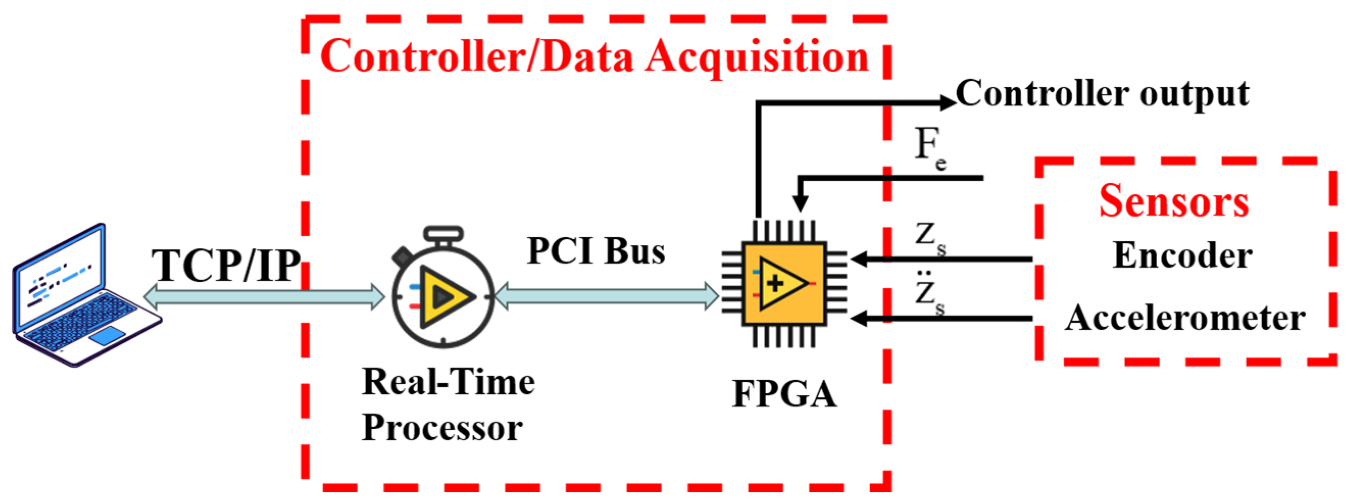
To further verify the effectiveness of the proposed ride height control strategy, an active suspension system was constructed by mechanically paralleling a permanent magnet synchronous linear motor (PMSLM) with a suspension spring. The electrical parameters of the linear motor are listed in
Table 1, and the control workflow of the experimental platform is illustrated in
Figure 7.
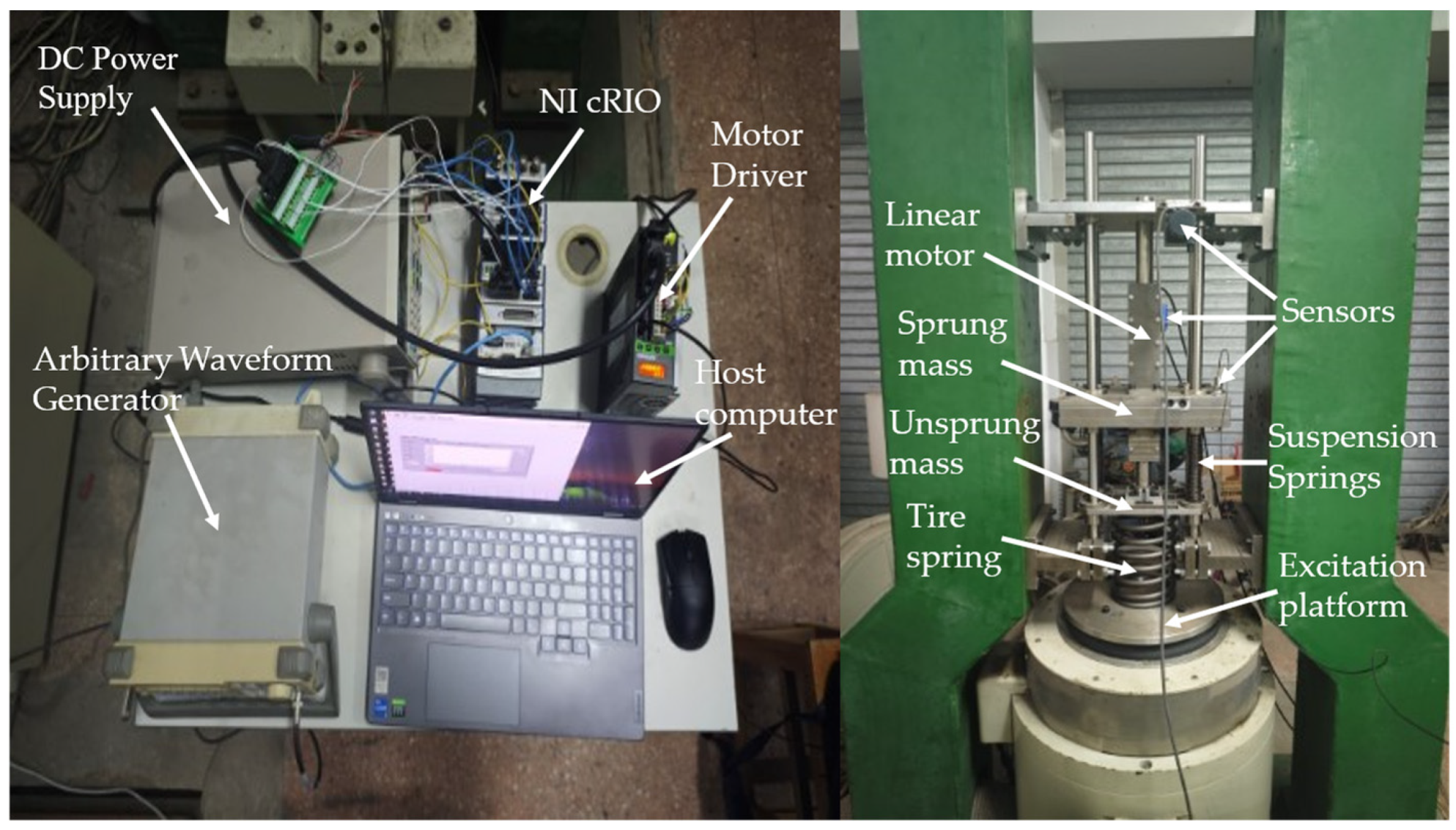
The experimental platform is shown in
Figure 8. The primary coil of the linear motor is rigidly connected to the sprung mass, while the secondary permanent magnet part is fixed to the unsprung mass. The linear motor is equipped with a built-in encoder that measures the relative displacement between the vehicle body and the wheel. The sprung and unsprung masses are connected via four guide rods and linear bearings, allowing smooth vertical sliding. An external draw-wire displacement encoder is used to measure the absolute body displacement, and an acceleration sensor is mounted on the sprung mass to capture vertical acceleration.
The control and data acquisition system consists of a host PC, an NI cRIO controller, NI data acquisition modules, various sensors, and a motor driver. The motor driver is configured to operate in current control mode, and all necessary power and signal wiring is completed to enable control of the linear motor and its driver. The motor control and data acquisition programs are developed on the LabVIEW FPGA platform. The control voltage signal is generated via the NI-9263 module and sent to the linear motor driver to achieve real-time control of the linear motor system, including ride height tracking. Meanwhile, the NI-9411 module is used to acquire encoder signals, and the NI-9234 module is used to acquire acceleration signals. All collected data is transmitted from the real-time (RT) controller to the host PC via a network stream. On the host side, various physical signals can be visualized, analyzed, and stored for further evaluation.
Based on the ride height regulation strategy proposed in
Section 3, the linear active disturbance rejection control (LADRC) algorithm was first implemented and discretized using the zero-order hold (ZOH) method. The discrete controller was then deployed to the LabVIEW FPGA platform. According to the physical parameters of the suspension system, the high-frequency gain was set to 0.04, the controller bandwidth to 16 rad/s, and the observer bandwidth to 96 rad/s. The control sampling period was configured to 200 μs. The external excitation signal was generated by a DG1022 arbitrary waveform generator and applied to the vibration platform. Under external excitation, the active suspension system responded dynamically. The absolute displacement of the vehicle body, measured by the displacement sensor, was used as the feedback signal. A target ride height was set via the host PC. The LADRC running on the LabVIEW FPGA computed the required active control force, which was then converted into an analog voltage signal. This voltage signal was output to the motor driver through the NI-9263 module, enabling the linear motor actuator to generate the corresponding control force to track the desired ride height.
Test Condition 1: Step Response Evaluation. The step input signal represents a sudden change in the desired vehicle body height, simulating scenarios such as abrupt road obstacles or active ride height adjustment.
Figure 9 and
Figure 10 and
Table 1 illustrate the displacement tracking performance and tracking error of the LADRC and PID controllers under the given step input.
As shown in
Figure 9 and
Figure 10 and
Table 2, under the given height command, the traditional PID controller exhibits a settling time of 1.3 s, an overshoot of 7.87%, and a steady-state error of 0.502 mm. In contrast, the LADRC achieves a faster settling time of 0.6 s with a significantly lower steady-state error of 0.05 mm. Moreover, the response of the LADRC is smoother and free from overshoot, demonstrating superior transient and steady-state performance.
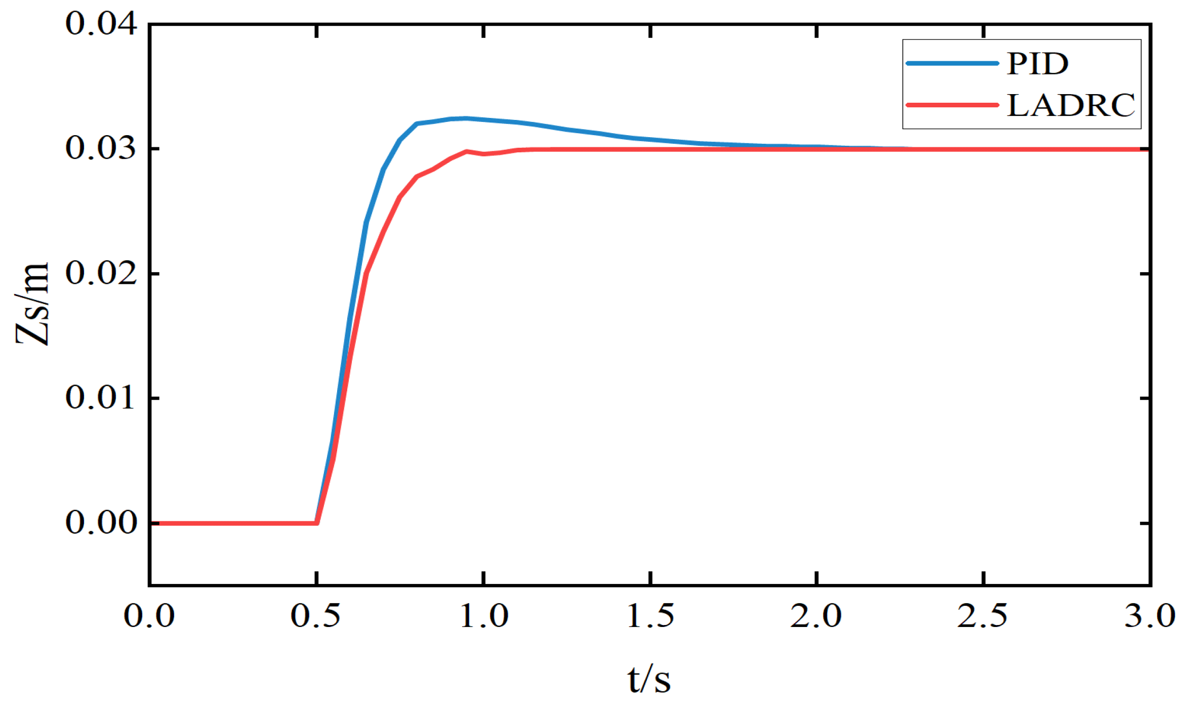
Under this test condition, the LADRC parameters and the current-loop PI controller parameters were kept identical in both the simulation and the experimental setup. The resulting sprung mass displacement curves for a 0.03 m upward step in body height are shown in
Figure 11. As illustrated, the vehicle body reaches the target height in a short time in both cases. Specifically, the adjustment time in the simulation is approximately 0.4 s, while in the experiment, it is around 0.6 s. The slightly longer adjustment time observed in the experiment is mainly due to practical factors such as unmodeled friction, actuator delay, and sensor noise. Nevertheless, the strong agreement between simulation and experimental results confirms the effectiveness and robustness of the proposed control strategy in real-world applications.
Test Condition 2: Ride Height Control under Random Road Excitation. In this test, the equilibrium position is set to 0 m and the target ride height is set to 0.03 m. The vehicle speed is 30 m/s, and the road excitation corresponds to a Class B road profile. The experimental results are presented in
Figure 12,
Figure 13 and
Figure 14 and
Table 3.
Figure 12,
Figure 13 and
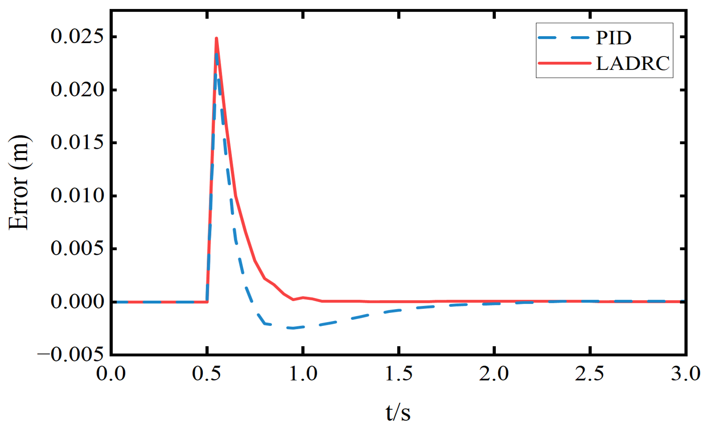
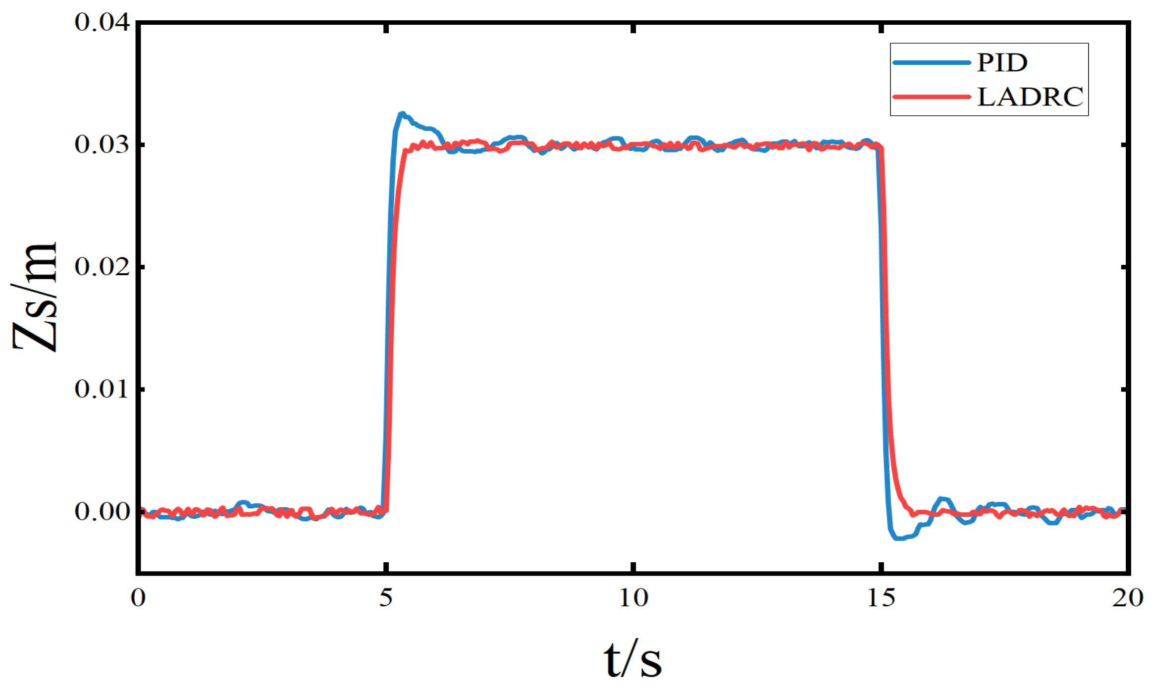
Figure 14 illustrate the time-domain performance differences between PID control and LADRC in terms of body displacement, electromagnetic thrust, and body acceleration. At 5 s, an upward control action is applied. The LADRC achieves a settling time of 0.55 s, whereas the PID controller requires 1.15 s. At 15 s, a downward control action returns the vehicle body to the equilibrium position, where LADRC settles within 0.65 s, while PID takes 1.05 s. Moreover, by comparison, the tracking error of LADRC is only about 38.4% of that of the PID controller, representing a 61.6% reduction in RMS error, further confirming the superior transient and steady-state performance of LADRC.
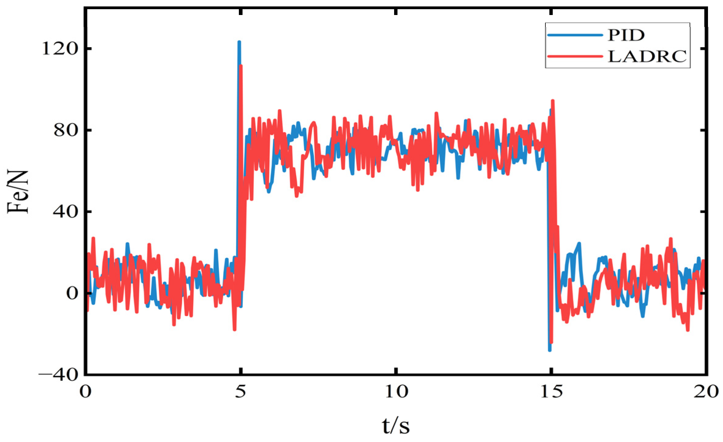
During the 5–15 s interval, the root mean square (RMS) value of the electromagnetic thrust under LADRC is 72.69 N, while that under PID control is 70.67 N, indicating a comparable average thrust level. The thrust output under PID control appears more stable. This is because LADRC continuously estimates and compensates for disturbances in real time to maintain ride height stability, which leads to larger thrust fluctuations during rapid adjustments.
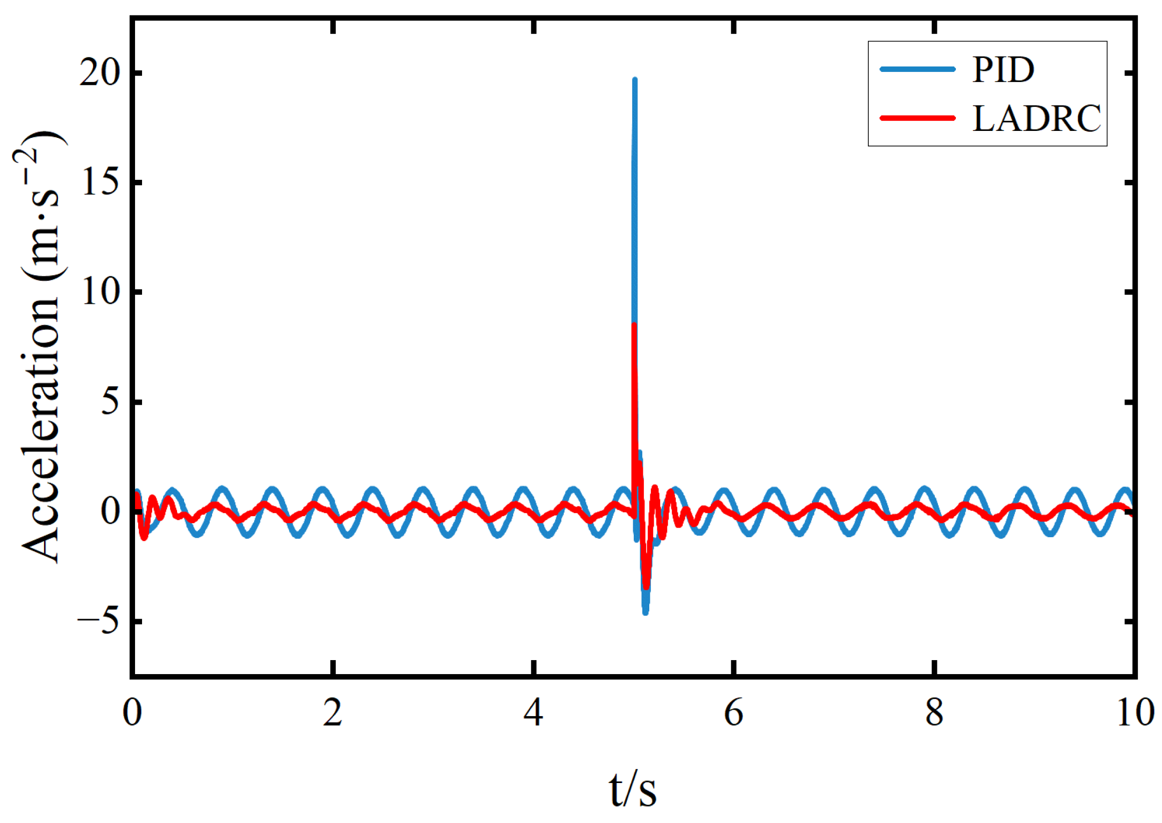
Figure 14 shows the time-domain response of body acceleration throughout the entire ride height adjustment process. As shown in
Table 2, the RMS value of body acceleration under LADRC is 0.33 m/s
2, compared to 0.376 m/s
2 under PID control, representing a 12.23% reduction. At the moments of upward and downward movement, both control strategies exhibit transient spikes in acceleration. The maximum body acceleration under LADRC is 5.095 m/s
2, while that under PID reaches 7.235 m/s
2, reflecting a 29.58% decrease with LADRC.
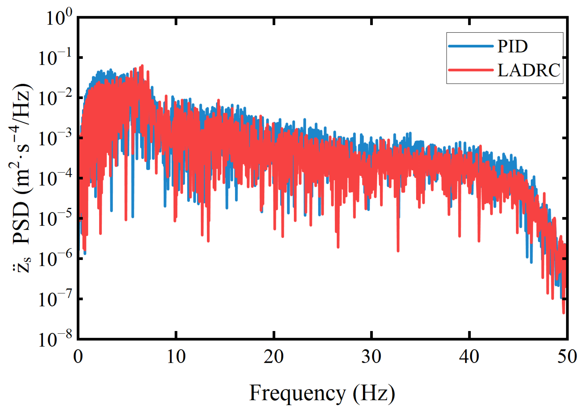
Figure 15 shows the power spectral density (PSD) of the body acceleration. It can be observed that the PID-controlled system exhibits higher PSD peaks across the entire frequency range, indicating a stronger response to disturbances, particularly under random road excitation or external inputs in the low- and mid-frequency bands. Although PID is effective in attenuating low-frequency disturbances, its performance in suppressing high-frequency noise is limited, which may lead to high-frequency oscillations and potential instability. In contrast, the PSD of the LADRC-controlled system remains consistently lower than that of PID across all frequencies, especially in the high-frequency range (>30 Hz), demonstrating its superior ability to suppress high-frequency disturbances. This indicates that LADRC offers better acceleration attenuation performance under random road excitation compared to PID control.
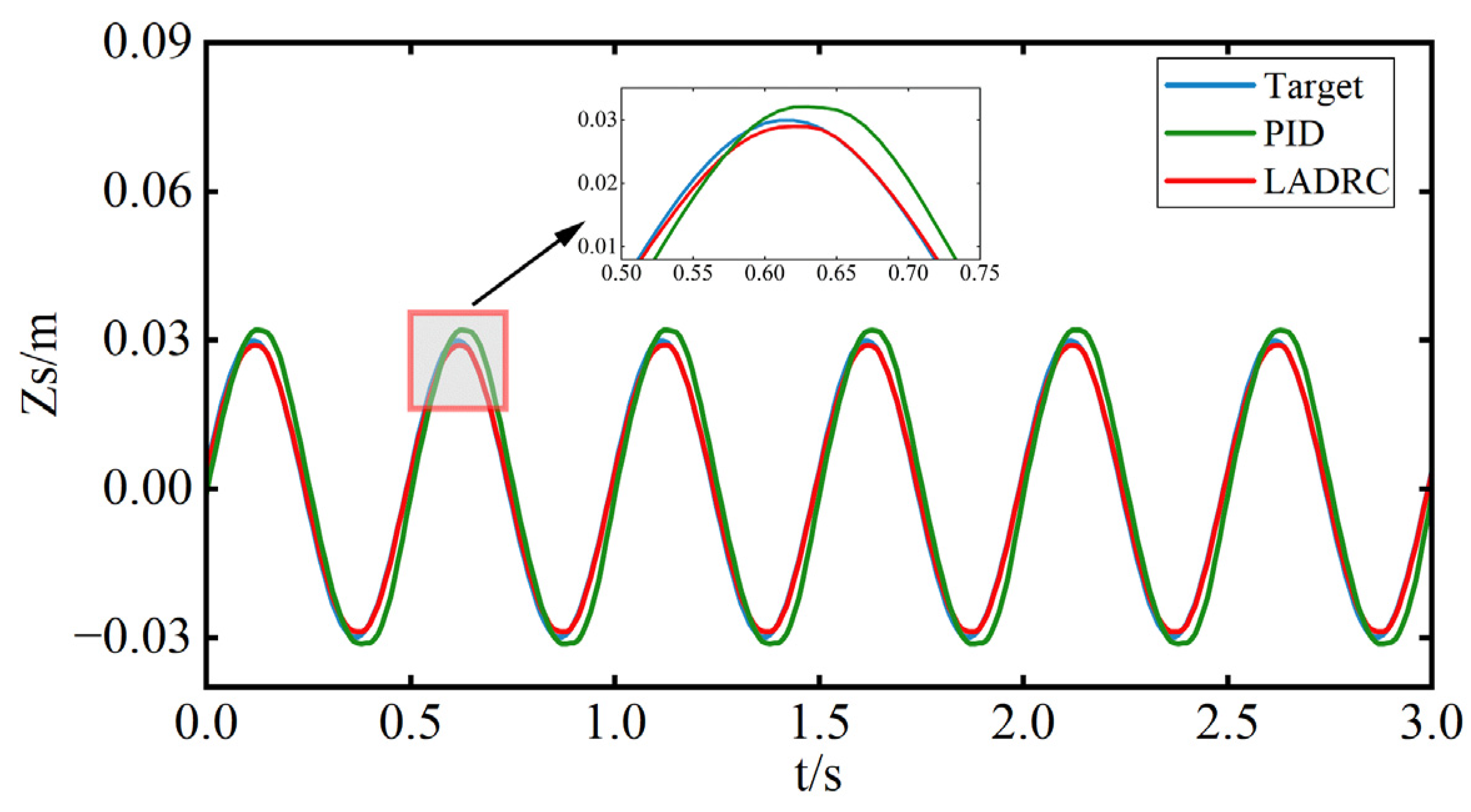
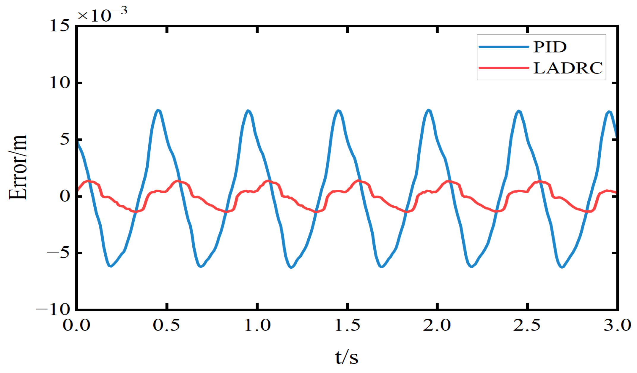
Test Condition 3: Sinusoidal Trajectory Tracking Test. A sinusoidal signal with a frequency of 0.2 Hz and an amplitude of 0.03 m is applied as the reference displacement trajectory for the sprung mass, in order to compare the tracking performance of the two controllers. The resulting sprung mass trajectory, tracking error, and acceleration response are shown in
Figure 16,
Figure 17 and
Figure 18, and the corresponding performance metrics are summarized in
Table 3.
As shown in the figure, both control strategies exhibit phase delay in the tracking curves, but the LADRC shows no noticeable overshoot and exhibits a smaller phase lag compared to PID. According to
Table 4, the LADRC demonstrates superior performance in sinusoidal trajectory tracking. Specifically, it reduces the peak tracking error by 81.5% and the RMS tracking error by 80.3% compared to PID. Additionally, the peak acceleration is reduced by 16.74%, and the RMS acceleration is reduced by 26.61%. These results indicate that LADRC outperforms PID in terms of both accuracy and stability, particularly during dynamic transitions, where it significantly reduces tracking error.
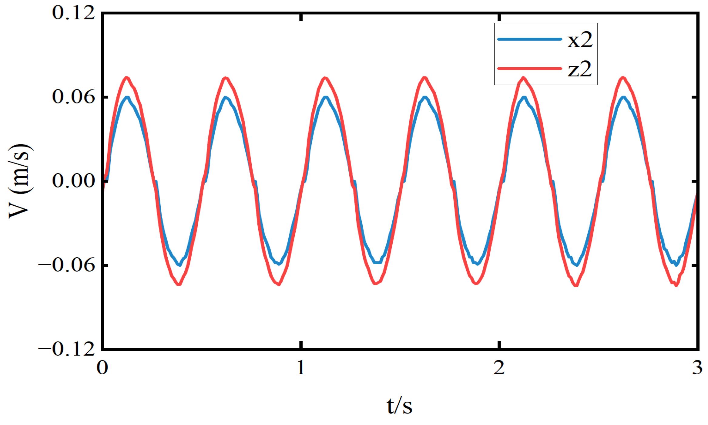
The actual and estimated data of the sprung mass position and velocity obtained by the LESO used in the LADRC are shown in the figures.
Figure 19 illustrates the position and its estimation, where the estimated curve closely overlaps with the actual position curve, indicating high estimation accuracy.
Figure 20 presents the velocity and its corresponding estimation. The estimated velocity generally follows the actual velocity well. However, there is a noticeable estimation error when the velocity undergoes sudden changes. This discrepancy may be attributed to a slight lag in the LESO’s response to abrupt disturbances. Nevertheless, overall, the LESO is capable of accurately tracking velocity variations, with estimation errors primarily occurring during transient moments. These errors have minimal impact on overall system stability.


