
Variable Power Tracking Control Strategy of Doubly Fed Induction Generators for Fast Frequency Responses


Abstract
1. Introduction
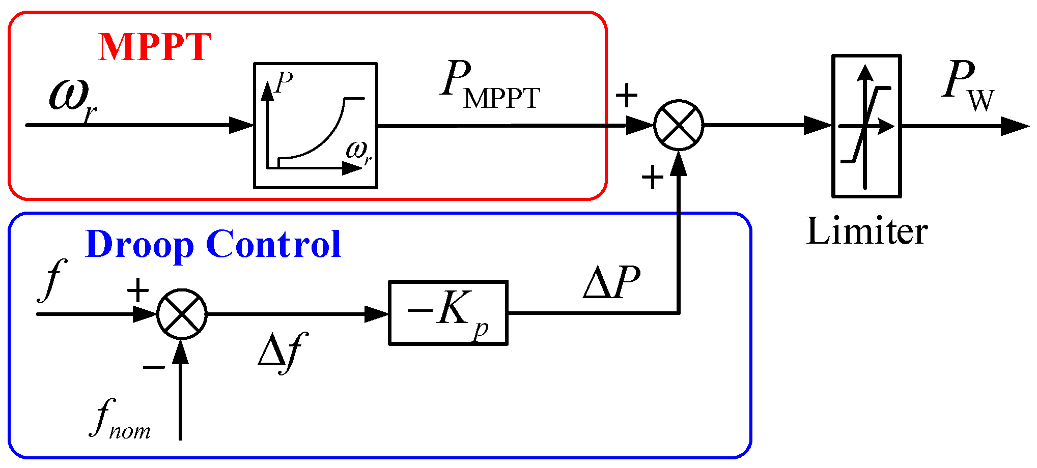
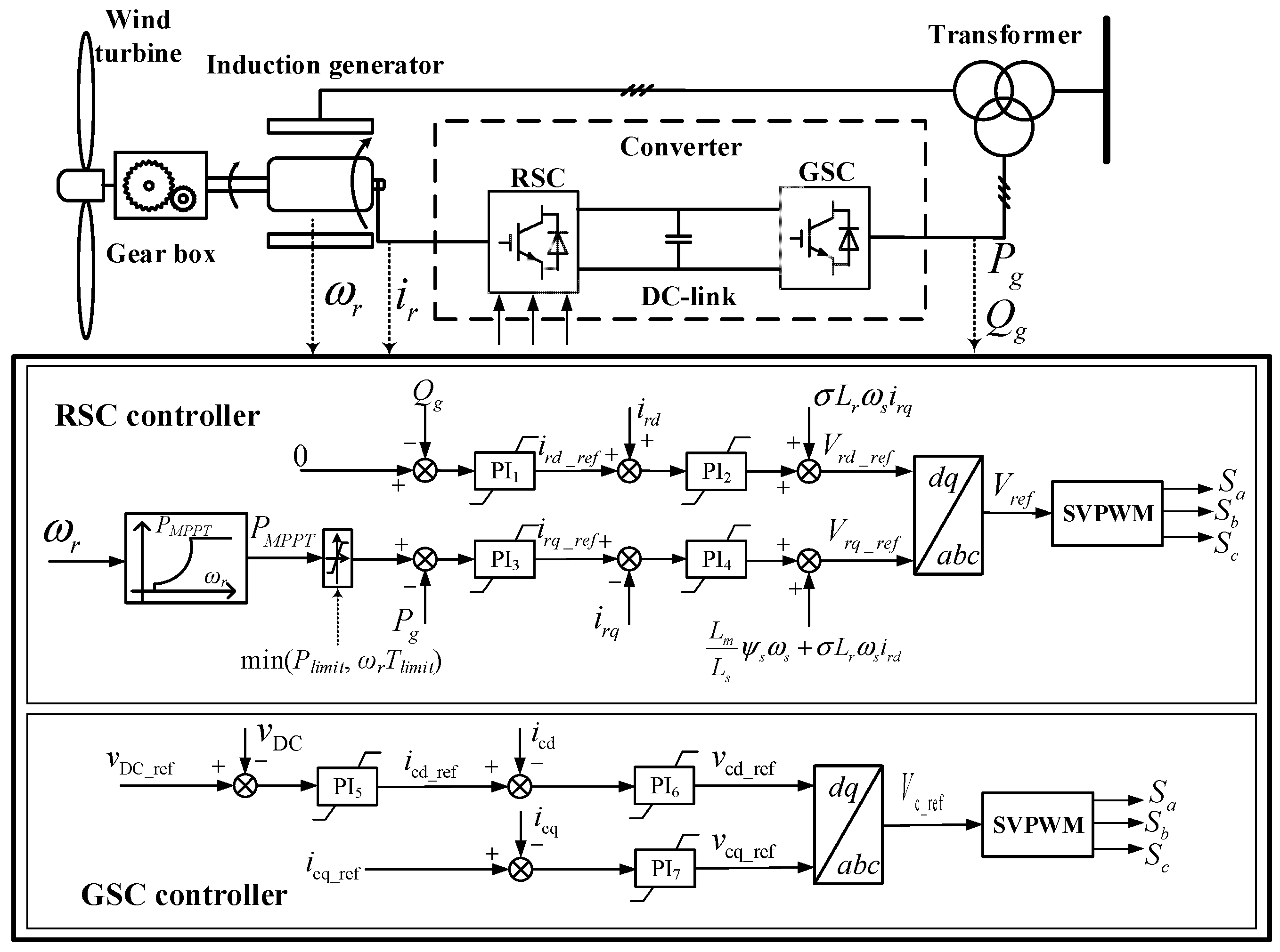
2. Control of DFIGs
3. Adaptive Frequency Regulation Scheme of DFIGs
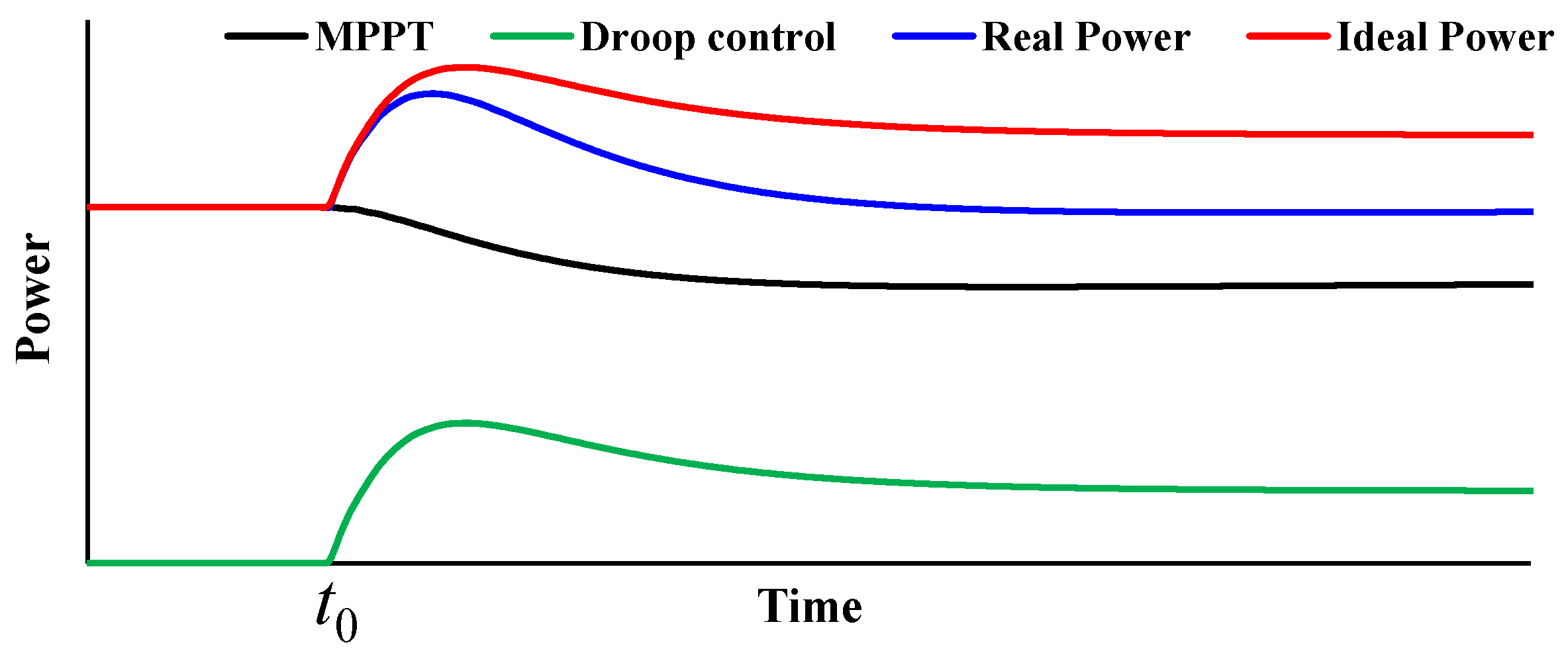
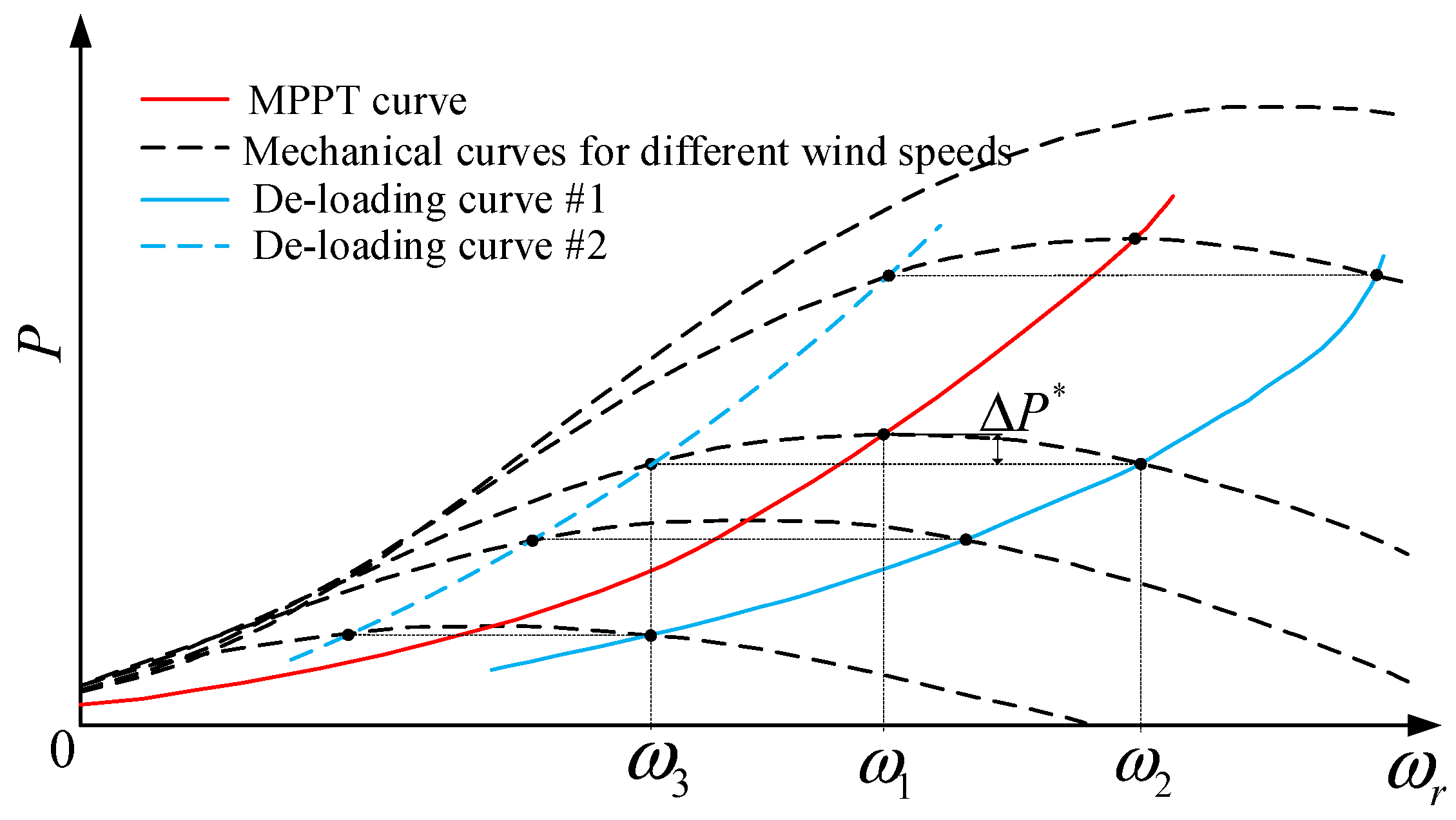
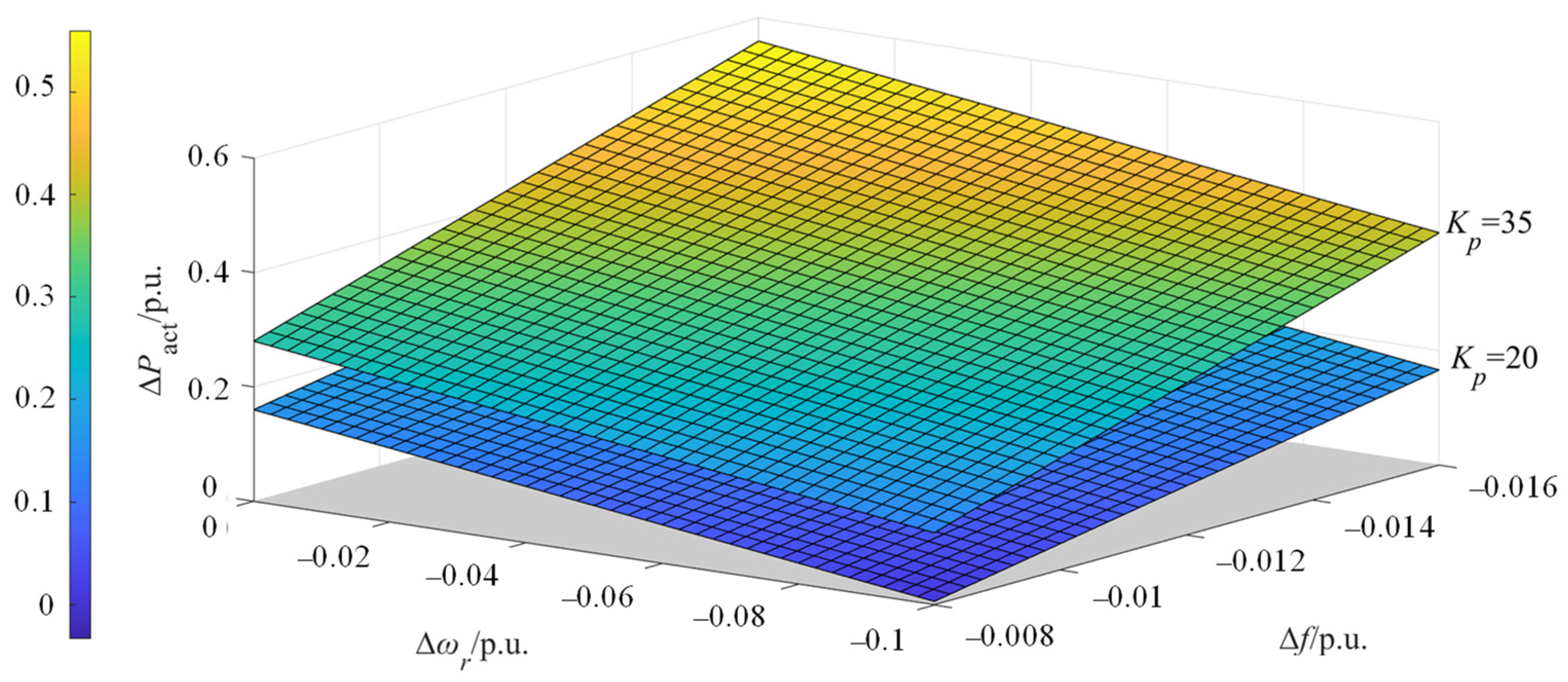
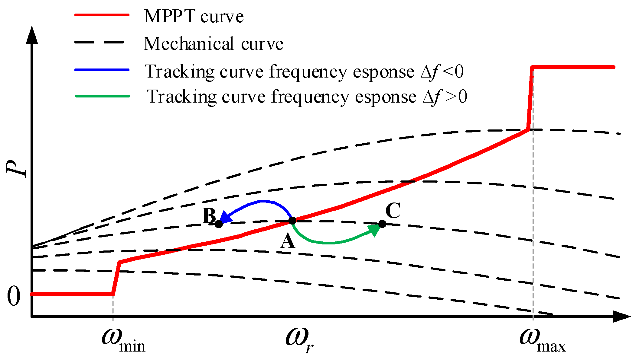
3.1. Dynamic Characteristics of Frequency Regulation Incremental Power for Droop Control
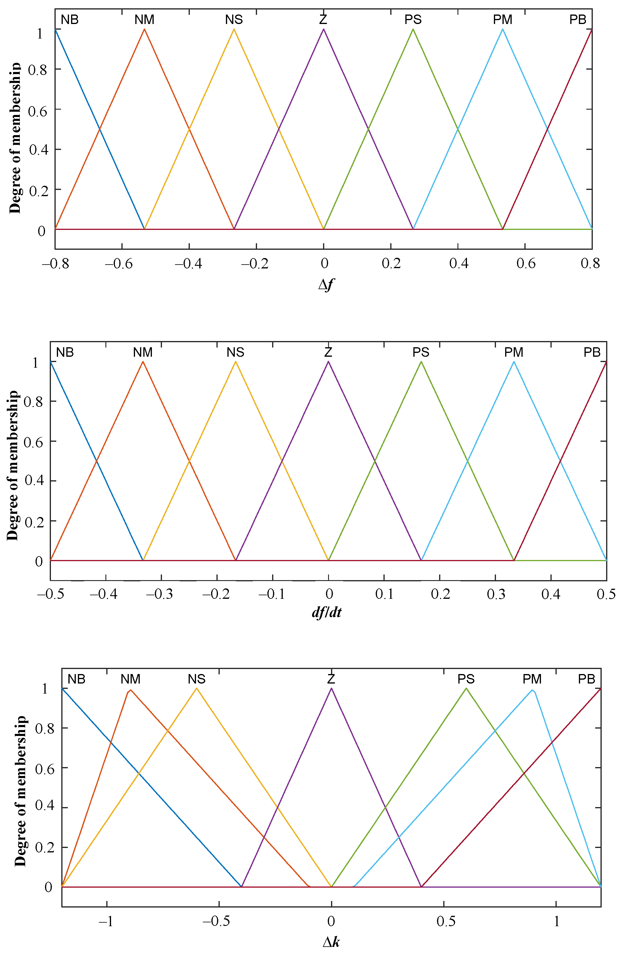
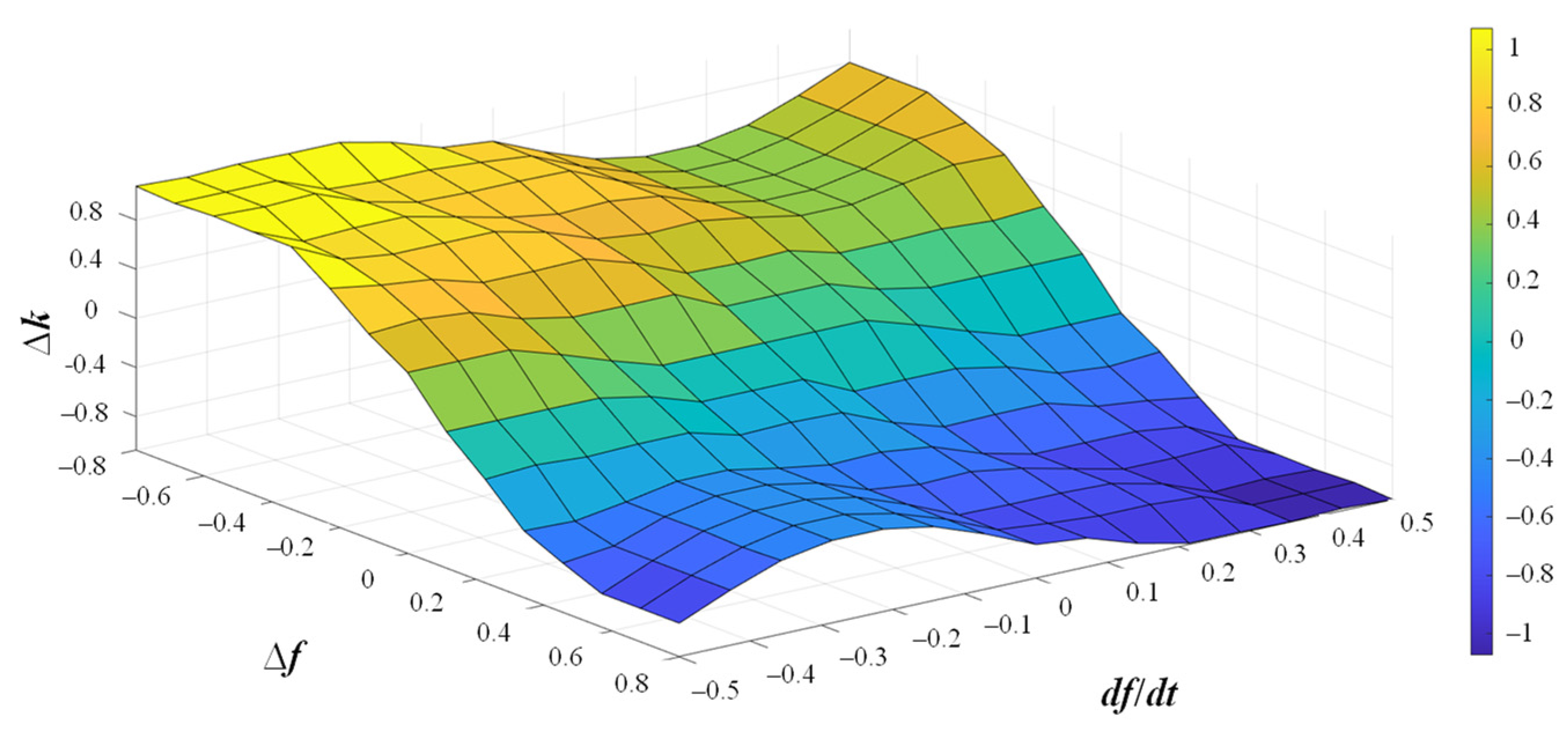
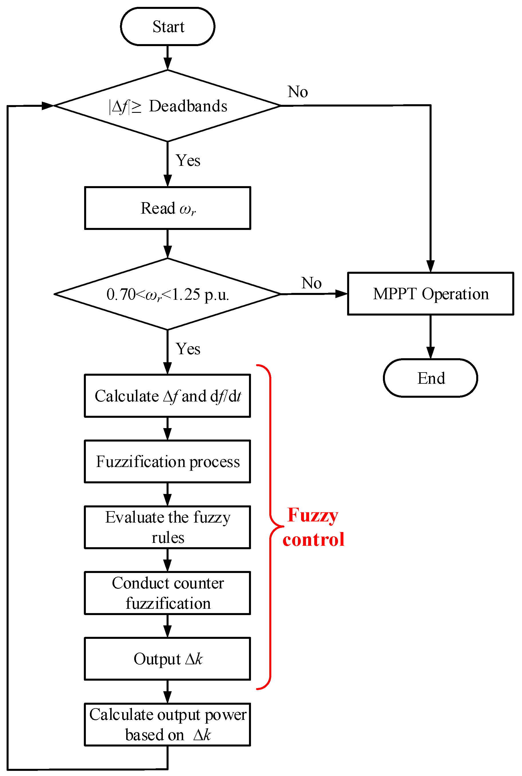
3.2. Proposed Frequency Regulation Scheme Based on Fuzzy Control
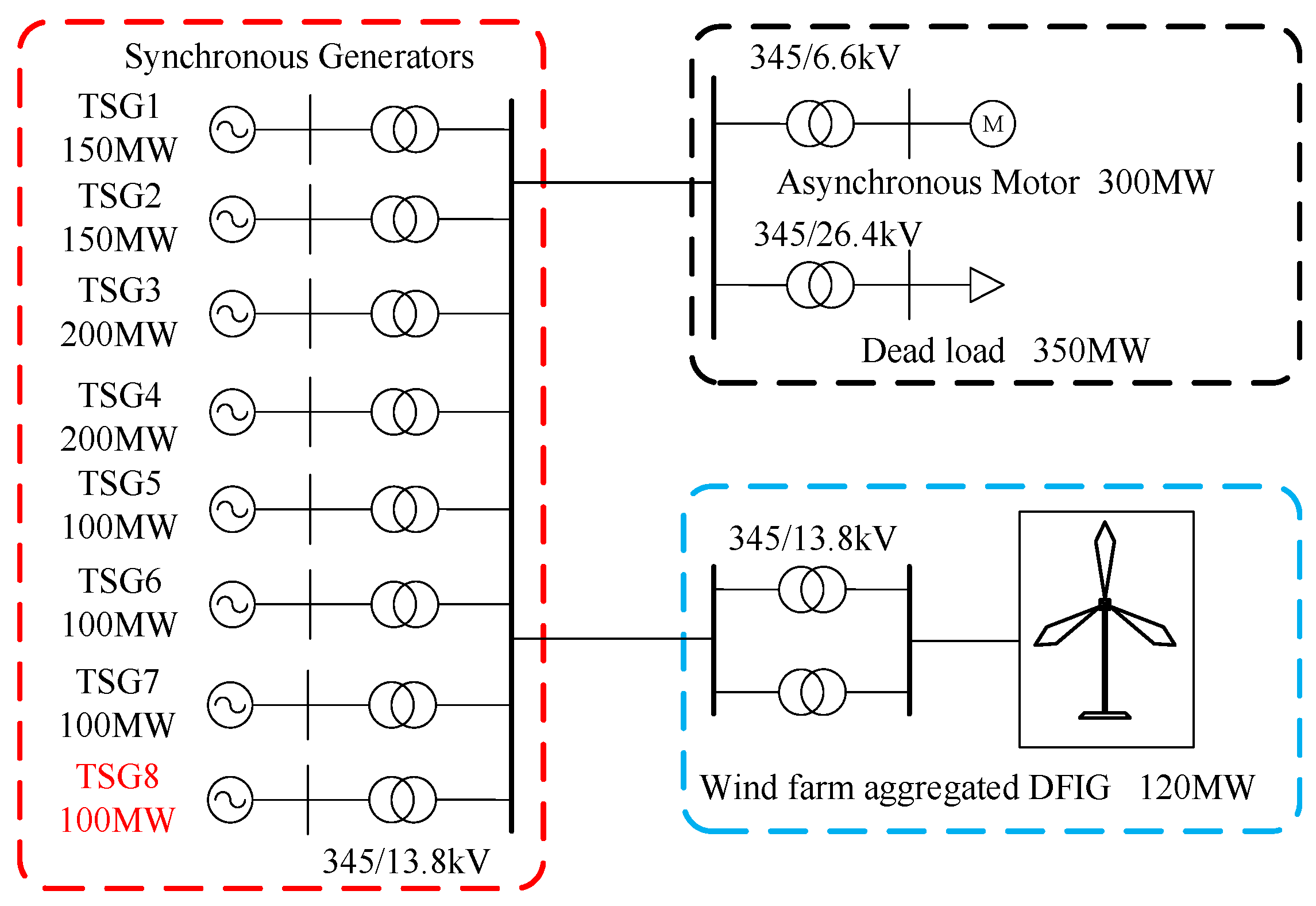
4. Model System and Simulation Results
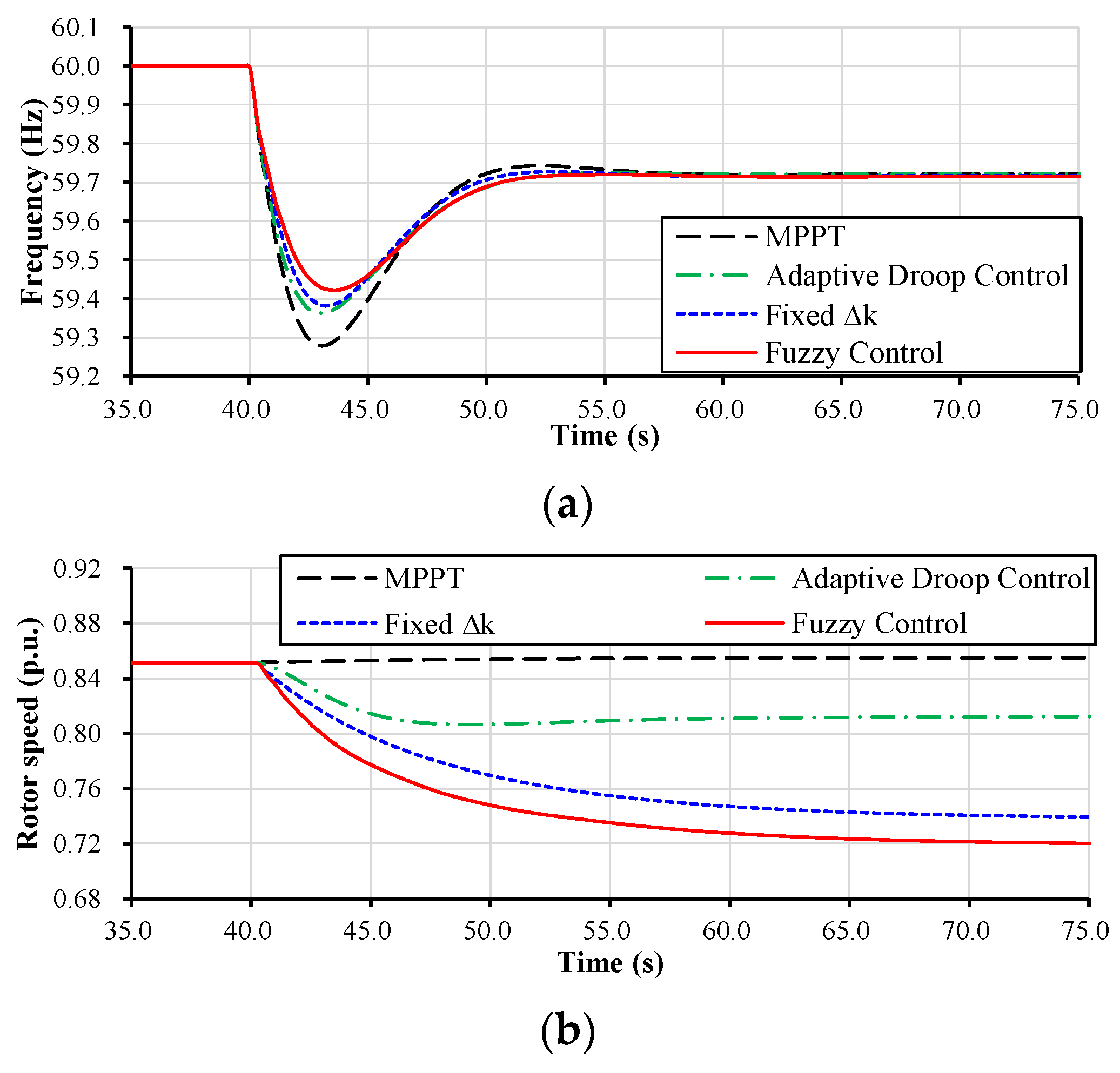
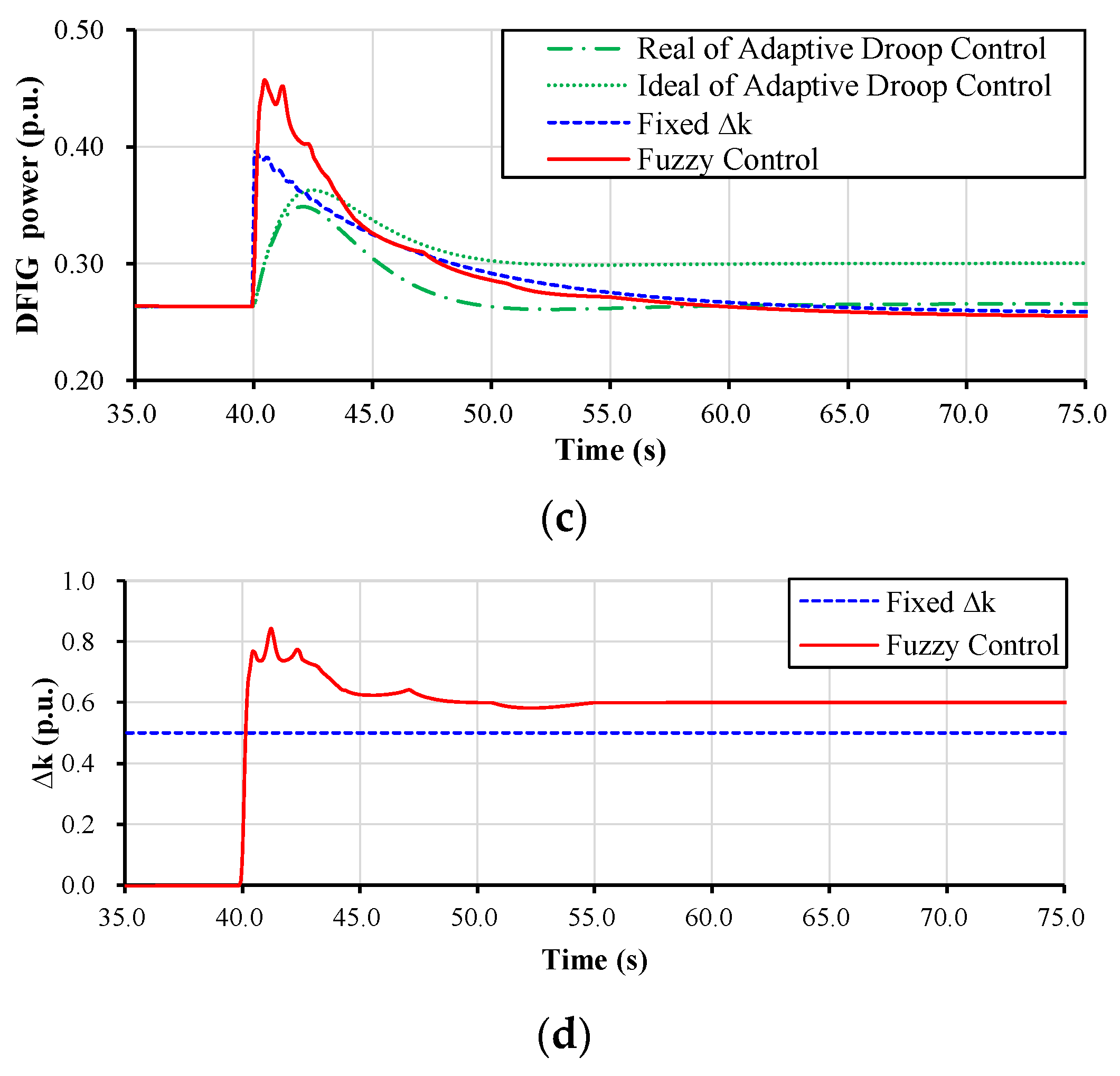
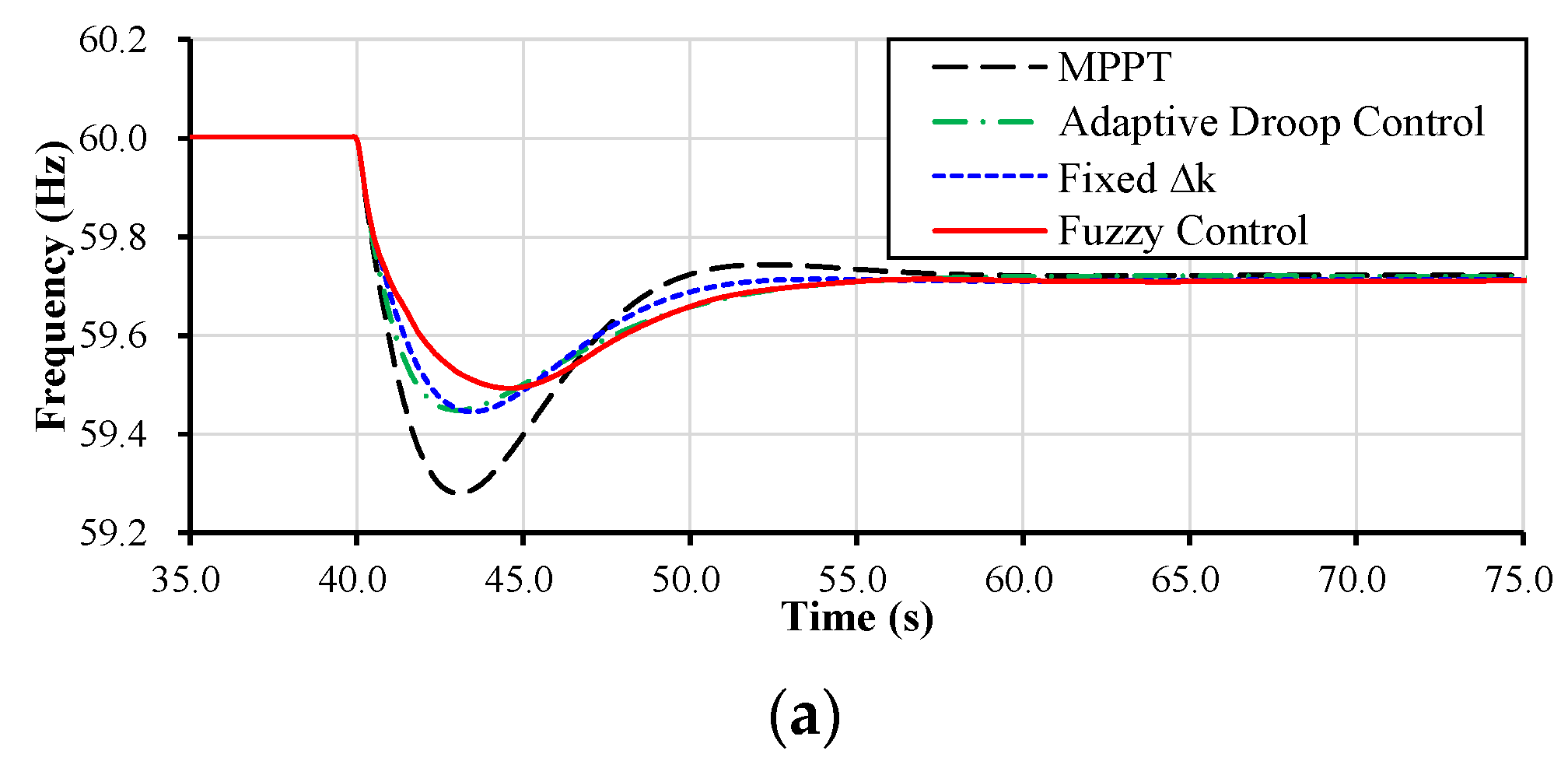
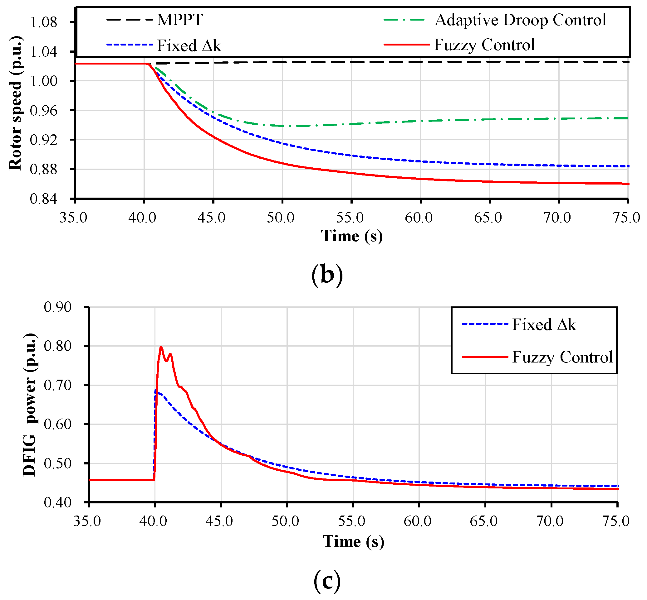
4.1. Case 1: Wind Speed = 7.5 m/s, Disturbance = 100 MW
4.2. Case 2: Wind Speed = 9.0 m/s, Disturbance = 100 MW
5. Conclusions
- (1)
- The power coefficient of the power tracking operation is effectively solved by introducing fuzzy control, which comprehensively considers the df/dt and ∆f, thus effectively solving the comprehensive problem of control coefficient allocation. The application of fuzzy control enables the system to respond more flexibly to complex and changing working environments, improving the robustness and adaptability of the control.
- (2)
- The proposed IDFR strategy exhibits excellent performance in the face of various interferences and operating conditions. By effectively adjusting the control coefficient of the power tracking operation, the system can maintain the frequency’s lowest point under different working conditions, and significantly improve the df/dt. This advantage makes the system more stable and responsive, with significantly enhanced adaptability.
Author Contributions
Funding
Data Availability Statement
Conflicts of Interest
References
- Global Wind Energy Council. Global Wind Report 2020. 2021. Available online: https://gwec.net/global-windreport-2021/#Download (accessed on 2 March 2021).
- Yang, D.; Li, J.; Jin, Z.; Yan, G.; Wang, X.; Ding, L.; Zhang, F.; Terzija, V. Sequential Frequency Regulation Strategy for DFIG and Battery Energy Storage System Considering Artificial Deadbands. Int. J. Electr. Power Energy Syst. 2024, 155, 109503. [Google Scholar] [CrossRef]
- Yang, D.; Wang, X.; Chen, W.; Yan, G.G.; Jin, Z.; Jin, E.; Zheng, T. Adaptive Frequency Droop Feedback Control-Based Power Tracking Operation of a DFIG for Temporary Frequency Regulation. IEEE Trans. Power Syst. 2024, 39, 2682–2692. [Google Scholar] [CrossRef]
- Lyu, X.; Jia, Y.; Dong, Z. Adaptive frequency responsive control for wind farm considering wake interaction. J. Mod. Power Syst. Clean Energy 2021, 9, 1066–1075. [Google Scholar] [CrossRef]
- Miller, N.; Shao, M.; Venataraman, S. California ISO: Frequency Response Study. 2019. Available online: http://www.uwig.org/Report-FrequencyResponseStudy.pdf (accessed on 9 November 2019).
- EirGrid; SONI. Ensuring a Secure, Reliable and Efficient Power System in a Changing Environment; Technic Report; EirGrid: Dublin, Ireland, 2011. [Google Scholar]
- National Grid UK. Grid Code Review Panel Paper, Future Frequency Response Services; National Grid Group: London, UK, 2010. [Google Scholar]
- GB/T 36994-2018; Wind Turbines-Test Procedure of Gird Adaptability. China Machinery Industry Federation: Beijing, China, 2018.
- Nordic Grid Code 2007 (Nordic Collection of Rules). Nordel. 2007. Available online: https://www.entsoe.eu/ (accessed on 10 November 2018).
- Hydro Québec TransÉnergie. Transmission Provider Technical Requirements for the Connection of Power Plants to the Hydro Québec Transmission System; Hydro Québec TransÉnergie: Montréal, QC, Canada, 2009. [Google Scholar]
- Zeni, L.; Rudolph, A.J.; Münster-Swendsen, J.; Margaris, I.; Hansen, A.D.; Sørensen, P. Virtual inertia for variable speed wind turbines. Wind. Energy 2013, 16, 1225–1239. [Google Scholar] [CrossRef]
- Yang, D.; Jin, Z.; Zheng, T.; Jin, E. An Adaptive Droop Control Strategy with Smooth Rotor Speed Recovery Capability for Doubly-fed Induction Generators. Int. J. Electr. Power Energy Syst. 2022, 115, 107532. [Google Scholar] [CrossRef]
- Ye, H.; Pei, W.; Qi, Z. Analytical modeling of inertial and droop responses from a wind farm for short-term frequency regulation in power systems. IEEE Trans. Power Syst. 2016, 31, 3414–3423. [Google Scholar] [CrossRef]
- Kheshti, M.; Lin, S.; Zhao, X.; Ding, L.; Yin, M.; Terzija, V. Gaussian Distribution-Based Inertial Control of Wind Turbine Generators for Fast Frequency Response in Low Inertia Systems. IEEE Trans. Sustain. Energy 2022, 13, 1641–1653. [Google Scholar] [CrossRef]
- Hu, Y.-L.; Wu, Y.-K. Approximation to frequency control capability of a DFIG-based wind farm using a simple linear gain droop control. IEEE Trans. Ind. Appl. 2019, 55, 2300–2309. [Google Scholar] [CrossRef]
- Lee, J.; Jang, G.; Muljadi, E.; Blaabjerg, F.; Chen, Z.; Kang, Y.C. Stable short-term frequency support using adaptive gains for a DFIG-based wind power plant. IEEE Trans. Energy Convers. 2016, 31, 1068–1079. [Google Scholar] [CrossRef]
- Jiang, Q.; Zeng, X.; Li, B.; Wang, S.; Liu, T.; Chen, Z.; Wang, T.; Zhang, M. Time-Sharing Frequency Coordinated Control Strategy for PMSG-Based Wind Turbine. IEEE J. Emerg. Sel. Top. Circuits Syst. 2022, 12, 268–278. [Google Scholar] [CrossRef]
- Zeng, X.; Liu, T.; Wang, S.; Dong, Y.; Chen, Z. Comprehensive coordinated control strategy of PMSG-based wind turbine for providing frequency regulation services. IEEE Access 2019, 7, 63944–63953. [Google Scholar] [CrossRef]
- Li, Y.; Xu, Z.; Wong, K.P. Advanced control strategies of PMSG-based wind turbines for system inertia support. IEEE Trans. Power Syst. 2017, 32, 3027–3037. [Google Scholar] [CrossRef]
- Zhao, H.; Wu, Q.; Hu, S.; Xu, H.; Rasmussen, C.N. Review of Energy Storage System for Wind Power Integration Support. Appl. Energy 2015, 137, 545–553. [Google Scholar] [CrossRef]
- Bao, W.; Wu, Q.; Ding, L.; Huang, S.; Terzija, V. A hierarchical inertial control scheme for multiple wind farms with BESSs based on ADMM. IEEE Trans. Sustain. Energy 2021, 12, 1461–1472. [Google Scholar] [CrossRef]
- Fernandez, L.M.; Garcia, C.A.; Jurado, F. Comparative study on the performance of control systems for doubly fed induction generator wind turbines operating with power regulation. Energy 2008, 33, 1438–1452. [Google Scholar] [CrossRef]
- Petersson, A. Analysis Modeling and Control of Doubly-Fed Induction Generators for Wind Turbines; Chalmers Tekniska Hogskola: Göteborg, Sweden, 2005. [Google Scholar]
- Ying, H. Constructing nonlinear variable gain controllers via the Taka-gieSugeno fuzzy control. IEEE Trans. Fuzzy Syst. 1998, 2, 226–234. [Google Scholar] [CrossRef]
- Bian, X.; Zhang, J.; Ding, Y.; Zhao, J.; Zhou, Q.; Lin, S. Microgrid frequency regulation involving low-wind-speed wind turbine generators based on deep belief network. IET Gener. Transm. Distrib. 2020, 14, 2046–2054. [Google Scholar] [CrossRef]
- Zhang, X.; Zhang, Y.; Fang, R.; Xu, D. Impedance Modeling and SSR Analysis of DFIG Using Complex Vector Theory. IEEE Access 2019, 7, 155860–155870. [Google Scholar] [CrossRef]


| Δk | df/dt | |||||||
|---|---|---|---|---|---|---|---|---|
| NB | NM | NS | Z | PS | PM | PB | ||
| Δf | NB | PB | PB | PB | PM | PS | PS | PM |
| NM | PB | PB | PM | PM | PS | PS | PM | |
| NS | PB | PM | PM | PS | PS | PS | PS | |
| Z | PS | PS | Z | Z | Z | NS | NS | |
| PS | NS | NS | NS | NS | NM | NM | NB | |
| PM | NM | NS | NS | NM | NM | NB | NB | |
| PB | NM | NS | NS | NM | NB | NB | NB | |
| Size of Disturbance (MW) | Wind Speed (m/s) | |
|---|---|---|
| Case 1 | 100 | 7.5 |
| Case 2 | 100 | 9.0 |
| Frequency Lowest Point (Hz) | Minimum Rotative Speed (p.u.) | Maximum Output Power of a DFIG (p.u.) | The Difference between Ideal Power and Actual Power (p.u.) | |
|---|---|---|---|---|
| MPPT | 59.28 | 0.85 | 0.26 | 0 |
| Adaptive droop control | 59.36 | 0.80 | 0.34 (real)/0.36 (ideal) | 0.02 |
| Fixed ∆k | 59.38 | 0.74 | 0.40 | 0 |
| Fuzzy control | 59.42 | 0.72 | 0.46 | 0 |
| Frequency Lowest Point (Hz) | Minimum Rotative Speed (p.u.) | Maximum Output Power of a DFIG (p.u.) | The Difference between Ideal Power and Actual Power (p.u.) | |
|---|---|---|---|---|
| MPPT | 59.28 | 1.02 | 0.46 | 0 |
| Adaptive droop control | 59.45 | 0.93 | 0.63 (real)/0.67 (ideal) | 0.04 |
| Fixed ∆k | 59.45 | 0.88 | 0.69 | 0 |
| Fuzzy control | 59.49 | 0.86 | 0.79 | 0 |
Disclaimer/Publisher’s Note: The statements, opinions and data contained in all publications are solely those of the individual author(s) and contributor(s) and not of MDPI and/or the editor(s). MDPI and/or the editor(s) disclaim responsibility for any injury to people or property resulting from any ideas, methods, instructions or products referred to in the content. |
© 2024 by the authors. Licensee MDPI, Basel, Switzerland. This article is an open access article distributed under the terms and conditions of the Creative Commons Attribution (CC BY) license (https://creativecommons.org/licenses/by/4.0/).
Share and Cite
Xue, X.; Huang, J.; Sang, S. Variable Power Tracking Control Strategy of Doubly Fed Induction Generators for Fast Frequency Responses. Electronics 2024, 13, 1071. https://doi.org/10.3390/electronics13061071
Xue X, Huang J, Sang S. Variable Power Tracking Control Strategy of Doubly Fed Induction Generators for Fast Frequency Responses. Electronics. 2024; 13(6):1071. https://doi.org/10.3390/electronics13061071
Chicago/Turabian StyleXue, Xiaocen, Jiejie Huang, and Shun Sang. 2024. "Variable Power Tracking Control Strategy of Doubly Fed Induction Generators for Fast Frequency Responses" Electronics 13, no. 6: 1071. https://doi.org/10.3390/electronics13061071
APA StyleXue, X., Huang, J., & Sang, S. (2024). Variable Power Tracking Control Strategy of Doubly Fed Induction Generators for Fast Frequency Responses. Electronics, 13(6), 1071. https://doi.org/10.3390/electronics13061071