
Interstacked Transformer Quad-Core VCOs


Abstract
1. Introduction
2. Multi-Core Oscillator Review
3. Interstacked Transformers
- -
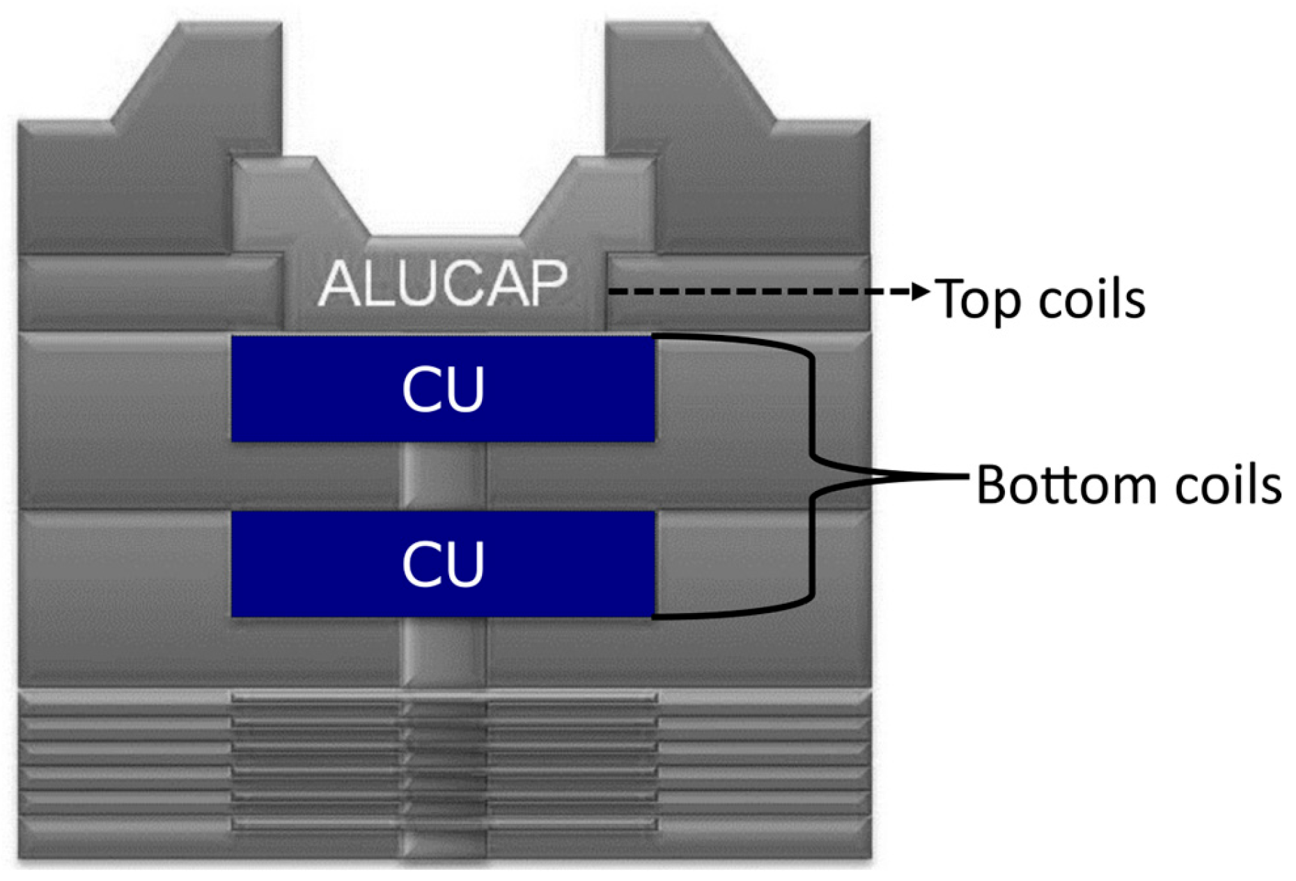
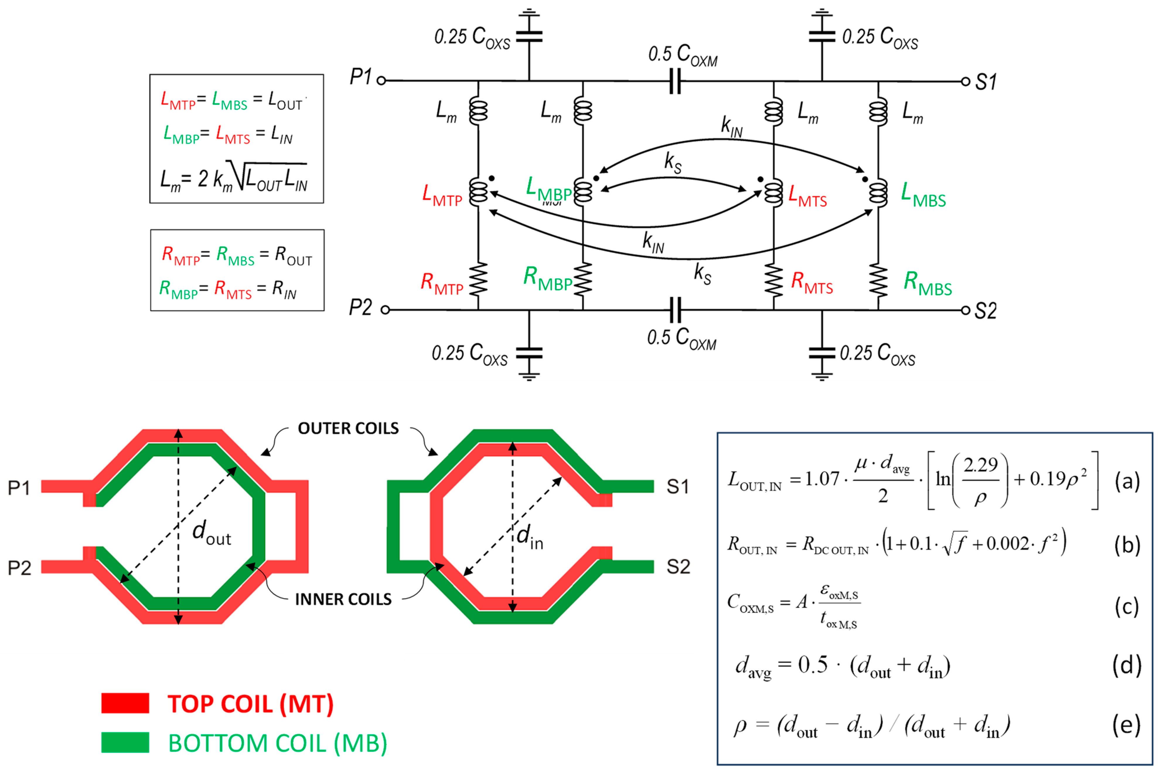
- The stacked coupling between outer (inner) spirals built in the top metal in primary and secondary windings, respectively, modeled by including a magnetic coupling factor, kS, between LMTP and LMBS (and between LMBP and LMTS).
- -
- The interleaved magnetic coupling between outer and inner spirals built in the same metal layer and belonging to different windings, modeled by adding a magnetic coupling factor, kIN, between LMTP and LMTS (and between LMBP and LMBS).
4. Design of an Interstacked Four-Port Transformer
5. Quad-Core VCO Design Based on an Interstacked Transformer
6. Conclusions
Author Contributions
Funding
Data Availability Statement
Conflicts of Interest
References
- Siddiq, K.; Watson, R.J.; Pennock, S.R.; Avery, P.; Poulton, R.; Dakin-Norris, B. Phase noise analysis in FMCW radar systems. In Proceedings of the 2015 European Microwave Conference (EuMC), Paris, France, 7–10 September 2015; pp. 501–504. [Google Scholar]
- Thurn, K.; Ebelt, R.; Vossiek, M. Noise in homodyne FMCW radar systems and its effects on ranging precision. In Proceedings of the 2013 IEEE MTT-S International Microwave Symposium Digest, Seattle, WA, USA, 2–7 June 2013; pp. 1–3. [Google Scholar]
- Hajimiri, A.; Lee, T.H. Design issues in CMOS differential LC oscillators. IEEE J. Solid-State Circuits 1999, 34, 717–724. [Google Scholar] [CrossRef]
- Krishnaswamy, H.; Hashemi, H. Inductor- and transformer-based integrated RF oscillators: A comparative study. In Proceedings of the IEEE Custom Integrated Circuits Conference, San Jose, CA, USA, 10–13 September 2006; pp. 381–384. [Google Scholar]
- Mazzanti, A.; Bevilacqua, A. On the phase noise performance of transformer-based CMOS differential-pair harmonic oscillators. IEEE Trans. Circuits Syst. I Regular Papers 2015, 62, 2334–2341. [Google Scholar] [CrossRef]
- Issakov, V.; Padovan, F. A dual-core 60 GHz push-push VCO with second harmonic extraction by mode separation. In Proceedings of the IEEE Radio Frequency Integrated Circuits Symposium (RFIC), Philadelphia, PA, USA, 10–12 June 2018; pp. 208–211. [Google Scholar]
- Issakov, V.; Padovan, F.; Rimmelspacher, J.; Weige, R.; Geiselbrechtinger, A. A 52-to-61 GHz push-push VCO in 28 nm CMOS. In Proceedings of the European Microwave Conference (EuMC), Madrid, Spain, 23–27 September 2018; pp. 1009–1012. [Google Scholar]
- Cavarra, A.; Papotto, G.; Parisi, A.; Finocchiaro, A.; Nocera, C.; Palmisano, G. Transformer-based VCO for W-band automotive radar applications. Electronics 2021, 10, 531. [Google Scholar] [CrossRef]
- Trotta, S.; Wintermantel, M.; Dixon, J.; Moeller, U.; Jammers, R.; Hauck, T.; Samulak, A.; Dehlink, B.; Shun-Meen, K.; Li, H.; et al. An RCP packaged transceiver chipset for automotive LRR and SRR systems in SiGe BiCMOS technology. IEEE Trans. Microw. Theory Tech. 2012, 60, 778–794. [Google Scholar] [CrossRef]
- Belfiore, F.; Calcagno, A.; Borgonovo, G.; Castro, M.G.; Pisasale, A.; Platania, M.; Vinciguerra, M.; Schiro, C.; Alessi, G.; Burgio, C.; et al. A 76 to 81 GHz packaged transceiver for automotive radar with FMCW modulator and ADC. In Proceedings of the 2017 European Radar Conference (EURAD), Nuremberg, Germany, 11–13 October 2017. [Google Scholar]
- Lou, L.; Tang, K.; Chen, B.; Guo, T.; Wang, Y.; Wang, W.; Fang, Z.; Liu, Z.; Zheng, Y. A 253mW/channel 4TX/4RX pulsed chirping phased-array radar TRX in 65nm CMOS for X-band synthetic-aperture radar imaging. In Proceedings of the 2018 IEEE International Solid-State Circuits Conference-(ISSCC), San Francisco, CA, USA, 11–15 February 2018; pp. 160–162. [Google Scholar]
- Ma, T.; Deng, W.; Chen, Z.; Wu, J.; Zheng, W.; Wang, S.; Qi, N.; Liu, Y.; Chi, B. A CMOS 76–81-GHz 2-TX 3-RX FMCW radar transceiver based on mixed-mode PLL chirp generator. IEEE J. Solid-State Circuits 2020, 55, 233–248. [Google Scholar] [CrossRef]
- Arai, T.; Usugi, T.; Murakami, T.; Kishimoto, S.; Utagawa, Y.; Kohtani, M.; Ando, I.; Matsunaga, K.; Arai, C.; Yamaura, S.; et al. A 77-GHz 8RX3TX transceiver for 250-m long-range automotive radar in 40-nm CMOS technology. IEEE J. Solid-State Circuits 2021, 56, 1332–1344. [Google Scholar] [CrossRef]
- Papotto, G.; Parisi, A.; Finocchiaro, A.; Nocera, C.; Cavarra, A.; Castorina, A.; Palmisano, G. A W-Band transmitter for automotive radar sensors in 28-nm FD-SOI CMOS. IEEE Trans. Microw. Theory Tech. 2023, 71, 4577–4587. [Google Scholar] [CrossRef]
- Ragonese, E.; Nocera, C.; Cavarra, A.; Papotto, G.; Spataro, S.; Palmisano, G. A comparative analysis between standard and mm-wave optimized BEOL in a nanoscale CMOS technology. Electronics 2020, 9, 2124. [Google Scholar] [CrossRef]
- Joseph, A.; Jain, V.; Ong, S.N.; Wolf, R.; Lim, S.F.; Singh, J. Technology positioning for mm wave applications: 130/90 nm SiGe BiCMOS vs. 28 nm RFCMOS. In Proceedings of the IEEE BiCMOS and Compound Semiconductor Integrated Circuits and Technology Symposium (BCICTS), San Diego, CA, USA, 15–17 October 2018; pp. 18–21. [Google Scholar]
- Ragonese, E.; Papotto, G.; Nocera, C.; Cavarra, A.; Palmisano, G. CMOS automotive radar sensors: Mm Wave circuit design challenges. IEEE Trans. Circuits Syst. II Express Briefs 2022, 69, 2610–2616. [Google Scholar] [CrossRef]
- Ahmadi-Mehr, S.A.-R.; Tohidian, M.; Staszewski, R.B. Analysis and design of a multi-core oscillator for ultra-low phase noise. IEEE Trans. Circuits Syst. I Regul. Pap. 2016, 63, 529–539. [Google Scholar] [CrossRef]
- Deng, Z.; Niknejad, A.M. A 4-port-inductor-based VCO coupling method for phase noise reduction. IEEE J. Solid-State Circuits 2011, 46, 1772–1781. [Google Scholar] [CrossRef]
- Iotti, I.; Mazzanti, A.; Svelto, F. Insights into phase-noise scaling in switch-coupled multi-core LC VCOs for E-Band adaptive modulation links. IEEE J. Solid-State Circuits 2017, 52, 1703–1718. [Google Scholar] [CrossRef]
- Murphy, D.; Darabi, H. A 27-GHz quad-core CMOS oscillator with no mode ambiguity. IEEE J. Solid-State Circuits 2018, 53, 3208–3216. [Google Scholar] [CrossRef]
- Rimmelspacher, J.; Weigel, R.; Hagelauer, V.; Issakov, V. A Quad-core 60 GHz push-push 45 nm SOI CMOS VCO with −101.7 dBc/Hz phase noise at 1 MHz offset, 19% continuous FTR and −187 dBc/Hz FoMT. In Proceedings of the IEEE European Solid State Circuits Conference (ESSCIRC), Dresden, Germany, 3–6 September 2018; pp. 138–141. [Google Scholar]
- Long, J.R. Monolithic transformers for silicon RF IC design. IEEE J. Solid-State Circuits 2000, 35, 1368–1382. [Google Scholar] [CrossRef]
- Long, J.R. On-chip transformer design and application to RF and mm-wave front-ends. In Proceedings of the IEEE Custom Integrated Circuits Conference (CICC), Austin, TX, USA, 3 May 2017; pp. 1–43. [Google Scholar]
- Rimmelspacher, J.; Breun, S.; Werthof, A.; Geiselbrechtinger, A.; Weigel, R.; Issakov, V. Experimental comparison of integrated transformers in a 28 nm bulk CMOS technology. In Proceedings of the European Microwave Conference (EuMC), Madrid, Spain, 23–27 September 2018; pp. 1097–1100. [Google Scholar]
- Spataro, S.; Ragonese, E. Design and optimization of silicon-integrated inductive components for automotive radar applications in K- and W-bands. In Proceedings of the 2020 AEIT International Conference of Electrical and Electronic Technologies for Automotive (AEIT AUTOMOTIVE), Torino, Italy, 18–20 November 2020; pp. 1–6. [Google Scholar]
- Bevilacqua, A. Fundamentals of integrated transformers: From principles to applications. IEEE Solid-State Circuits Mag. 2020, 12, 86–100. [Google Scholar] [CrossRef]
- Ragonese, E.; Sapone, G.; Palmisano, G. High-performance interstacked transformers for mm-wave ICs. Microw. Opt. Technol. Lett. 2010, 52, 2160–2163. [Google Scholar] [CrossRef]
- Giammello, V.; Ragonese, E.; Palmisano, G. A transformer-coupling current reuse SiGe HBT power amplifier for 77-GHz automotive radar. IEEE Trans. Microw. Theory Tech. 2012, 60, 1676–1683. [Google Scholar] [CrossRef]
- Ragonese, E.; Sapone, G.; Giammello, V.; Palmisano, G. Analysis and modeling of interstacked transformers for mm-wave applications. Analog. Integr. Circuits Signal Process. 2012, 72, 121–128. [Google Scholar] [CrossRef]
- Mohan, S.S.; del Mar Hershenson, M.; Boyd, S.P.; Lee, T.H. Simple accurate expressions for planar spiral inductances. IEEE J. Solid-State Circuits 1999, 34, 1419–1424. [Google Scholar] [CrossRef]
- Cathelin, A. Fully depleted silicon on insulator devices CMOS: The 28-nm node is the perfect technology for analog, RF, mmW, and mixed-signal system-on-chip integration. IEEE Solid-State Circuits Mag. 2017, 9, 18–26. [Google Scholar] [CrossRef]
- Liang, H.-B.; Lin, Y.-S.; Chen, C.-C.; Lee, J.-H. Optimization of PGS pattern of transformers/inductors in standard RF BiCMOS technology for RFIC applications. In Proceedings of the IEEE Radio Frequency Integrated Circuits (RFIC) Symposium, San Francisco, CA, USA, 10–13 June 2006; p. 4. [Google Scholar]
- Spataro, S.; Salerno, N.; Papotto, G.; Ragonese, E. The effect of a metal PGS on the Q-factor of spiral inductors for RF and mm-wave applications in a 28-nm CMOS technology. Int. J. RF Microw. Comput.-Aided Eng. 2020, 30, e22368. [Google Scholar] [CrossRef]
- Mansour, I.; Aboualalaa, M.; Barakat, A.; Allam, A.; Abdel-Rahman, A.B.; Abo-Zahhad, M.; Pokharel, R.K. Analysis and implementation of high-Q CT inductor for compact and wide-tuning range Ku-band VCO. IEEE Microw. Wirel. Compon. Lett. 2020, 30, 802–805. [Google Scholar] [CrossRef]


| Parameter | Value | Unit |
|---|---|---|
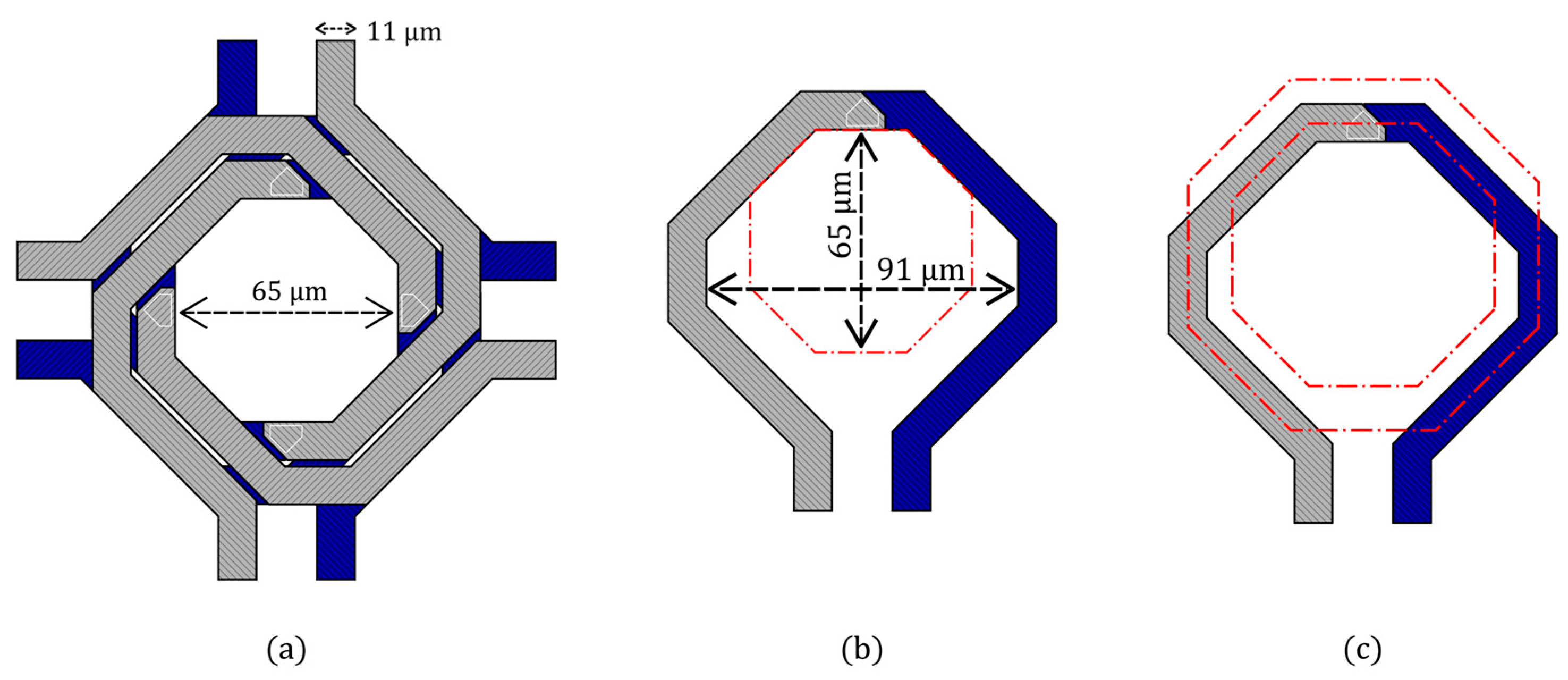
| Coil width | 11 | [μm] |
| Inner diameter 1, dIN | 65 | [μm] |
| Outer diameter 1, dOUT | 91 | [μm] |
| X-size | 157 | [μm] |
| Y-size | 157 | [μm] |
| Area | 0.025 | [mm2] |
| Mode | Inductance (pH) | Q-Factor |
|---|---|---|
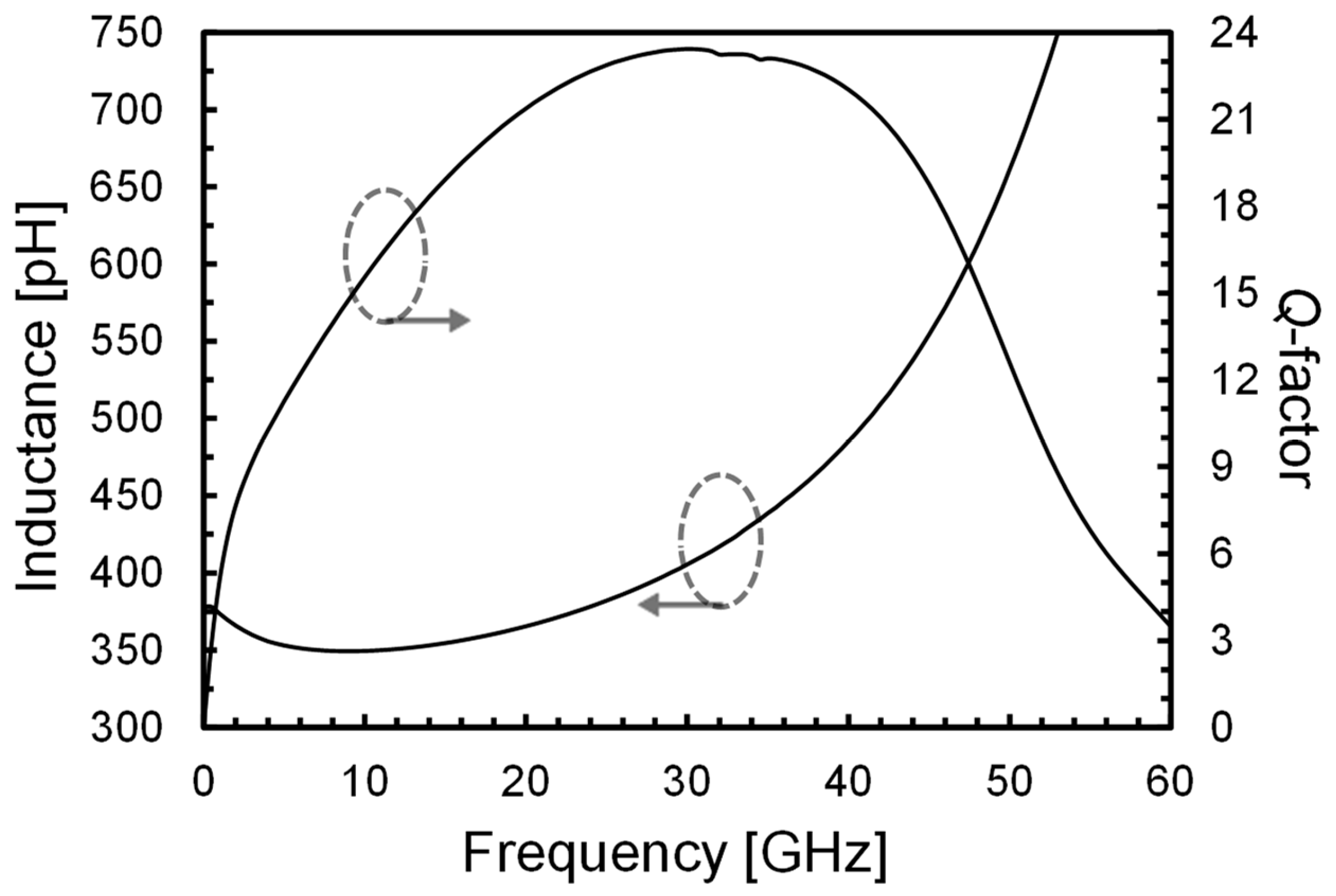
| 1 (desired) | 363 | 21.0 |
| 2 (undesired) | 71.2 | 6.15 |
| 3 (undesired) | 44.6 | 6.06 |
| 4 (undesired) | 64.5 | 5.84 |
| [20] | [21] | [22] | This Work | |
|---|---|---|---|---|
| Inductor topology | Single-turn | Four-port | Stacked | Interstacked |
| VCO topology | Class-B, NMOS-only, tail filtering | Complementary cross-coupled, 4tail filtering | NMOS-only, tail filtering, push-push | Complementary cross-coupled |
| Technology | 55 nm BiCMOS | 40 nm CMOS | 45 nm PDSOI CMOS | 28 nm FDSOI CMOS |
| Frequency (GHz) | 20 | 26.45 | 60.5 | 19.125 |
| Tuning range (%) | 15 | 26 | 19 | 20 |
| Tuning range type | analog and discrete | analog and discrete | analog-only | analog and discrete |
| PN @ 1 MHz (dBc/Hz) | −118.5 | −109.5 | −101.7 | −112.6 |
| PN @ 1 MHz from 19.125 GHz (dBc/Hz) | −118.9 | −112.3 | −111.7 | −112.6 |
| VDD (V) | 1.2 | 0.95 | 1 | 1.2 |
| Current (mA) | 36 | 17 | 40 | 6 |
| Power (mW) | 43 | 16 | 40 | 7.2 |
| Area (mm2) | 0.6 | 0.1 | 0.044 | 0.025 |
| FoM (dBc/Hz) | −188.2 | −186.8 | −181.3 | −189.6 |
| FoMT (dBc/Hz) | −191.7 | −195.0 | −186.9 | −195.6 |
| FoMA (dBc/Hz) | −190.4 | −196.8 | −194.9 | −205.6 |
Disclaimer/Publisher’s Note: The statements, opinions and data contained in all publications are solely those of the individual author(s) and contributor(s) and not of MDPI and/or the editor(s). MDPI and/or the editor(s) disclaim responsibility for any injury to people or property resulting from any ideas, methods, instructions or products referred to in the content. |
© 2024 by the authors. Licensee MDPI, Basel, Switzerland. This article is an open access article distributed under the terms and conditions of the Creative Commons Attribution (CC BY) license (https://creativecommons.org/licenses/by/4.0/).
Share and Cite
Tripoli, D.; Maiellaro, G.; Pavone, S.C.; Ragonese, E. Interstacked Transformer Quad-Core VCOs. Electronics 2024, 13, 927. https://doi.org/10.3390/electronics13050927
Tripoli D, Maiellaro G, Pavone SC, Ragonese E. Interstacked Transformer Quad-Core VCOs. Electronics. 2024; 13(5):927. https://doi.org/10.3390/electronics13050927
Chicago/Turabian StyleTripoli, Daniele, Giorgio Maiellaro, Santi Concetto Pavone, and Egidio Ragonese. 2024. "Interstacked Transformer Quad-Core VCOs" Electronics 13, no. 5: 927. https://doi.org/10.3390/electronics13050927
APA StyleTripoli, D., Maiellaro, G., Pavone, S. C., & Ragonese, E. (2024). Interstacked Transformer Quad-Core VCOs. Electronics, 13(5), 927. https://doi.org/10.3390/electronics13050927