Abstract
This manuscript examines the output characteristics of a dual three-phase synchronous reluctance motor (DT-SynRM) according to two winding arrangements under normal and half-control modes. In the case of the DT-SynRM, it can operate by using all of the dual three-phase systems (the normal control) or one of the dual three-phase systems (the half control). In this paper, conventional winding function theory (WFT) is applied, because the output characteristic can be predicted by the inductance behavior. According to the WFT, the inductance value can be affected by the winding function, the turn function, and the inverse air gap function. As a result, the rotor barrier shape as well as the winding configuration are the most important factors that have an effect on the performance of the DT-SynRM. Therefore, the effect of the rotor barrier design on the performance is analyzed when the winding configuration and control mode are different. Finally, the validity of the torque characteristic is substantiated through experimental verification.
1. Introduction
Multi-phase motors have been utilized in military equipment, aircraft, and electric vehicles, because these motors have a variety of advantages, such as high performance, redundancy, reliability, and fault tolerance capabilities [1,2,3,4,5]. In particular, the interest in multi-phase motors in the field of electric vehicles has increased as the power level has increased [6,7,8]. Among the multi-phase topologies, the multi-three-phase (MT) machine is more popular than the four-phase, five-phase, and seven-phase machines because it exhibits high reliability and employs commercial standard three-phase inverters [9,10,11,12,13,14]. In particular, in the case of a dual three-phase (DT) motor, when there are occasionally worse conditions, such as faults, it can work only using the half-three-phase system [15,16], and this is defined as the half-control (HC) mode. If the motor operates under the HC mode, the torque characteristic will be reduced, compared with the whole dual-three-phase system. Therefore, it is necessary to predict the characteristics of the motor under the HC mode conditions.
In the case of n-phase electric motors, stator phase inductances exist [17]. For example, a three-phase motor has nine stator phase inductances. In a DT motor, there are thirty-six stator phase inductances. Although the number of phases compared with the three-phase motor is doubled, the number of inductances is quadrupled. Therefore, in order to analyze the characteristics of DT motors, it is helpful to compute the inductance components. To obtain the inductance behaviors, winding function theory (WFT) is applied in this paper. WFT is simple and has a lower computational cost [18,19] compared with the finite element method (FEM). Thus, it is commonly used in many studies to calculate the inductance. According to WFT, the inductance value can be affected by the winding function, the turn function, and the inverse air gap function [20,21,22], and it has an effect on the output characteristic. Therefore, the torque characteristic based on the winding configuration and the rotor barrier design is analyzed using WFT.
The conference paper [23] discusses the analysis of a DT-synchronous reluctance motor (DT-SynRM) by WFT, and the main focus of [24] is to show the fault characteristics of a DT-SynRM. Unlike previous studies, this paper explores the correlation between the winding configuration and the rotor design factor in relation to the control mode. Specifically, an eight-pole 36-slot DT-SynRM is selected to analyze the characteristics based on the winding configuration and control mode. This study describes the inductance behavior and torque characteristics using the conventional WFT while optimizing the rotor barrier design. The inductances of the DT-SynRM are calculated for different winding configurations. Based on the typical three-phase system, the winding sectors of the eight-pole 36-slot model are split into four sections. As shown in Figure 1, the winding masses of the -system and -system are defined as winding-1 and winding-2, respectively, and the two different winding configurations are defined as W1122 and W1212, respectively [23,24]. Experimental tests on the W1122 and W1212 models are conducted under normal and HC mode conditions to verify the computation and analysis results. For the experiment, a prototype is developed that accommodates both winding configurations.
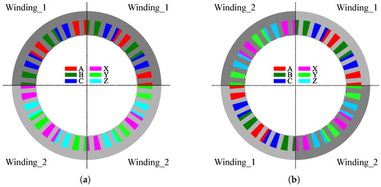
Figure 1.
Winding configurations. (a) W1122 model, (b) W1212 model [23].
2. DT-SynRM
The eight-pole and 36-slot DT-SynRM is chosen to verify the analysis of the DT-SynRM according to the winding configuration and control mode. A full model, including the stator and rotor parts and its winding part (WP), is shown in Figure 2 [23].
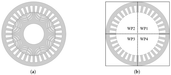
Figure 2.
Analysis model. (a) The whole scheme of the DT-SynRM [23] and (b) the winding part (WP).
In the case of the eight-pole and 36-slot DT-SynRM, the winding layout is repeated in the same pattern four times. Therefore, the stator can be divided into four WPs. Depending on how the input source is applied to these four WPs, the W1122 and W1212 models are determined. The winding layouts of the two models are shown in Figure 3. As a result, in the case of the W1122 and W1212 models, the winding arrangements according to the WPs are identical, but the order of the input sources is different.
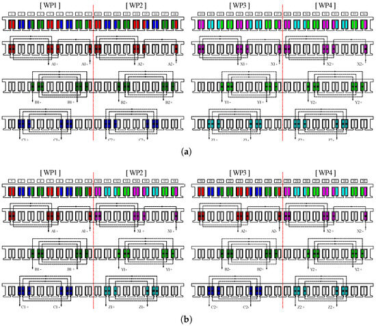
Figure 3.
Winding layout. (a) Winding of W1122 model and (b) winding of W1212 model.
When conducting an experiment, the winding configuration can be changed by using a winding tap, as shown in Figure 4. The winding tap is located at the upper side of the stator. Since all windings are divided into four WPs, each WP is selected according to the winding configuration type, which is the W1122 or W1212 model.
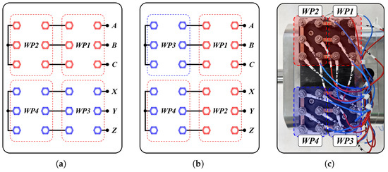
Figure 4.
Winding tap scheme. (a) For W1122, (b) for W1212, and (c) for experimental setup of W1122.
The specifications of the motor are presented in Table 1 [23]. The rated power is 1.6 kW and the rated torque is 11Nm when the rated voltage and current are 400 V and 8, respectively. In addition, the geometric parameters of the eight-pole, 36-slot DT-SynRM are shown in Table 2. W1122 and W1212 have the same geometric parameters except for the winding configuration.

Table 1.
Specifications of motor.
Table 2.
Geometry of motor.
3. Inductance Behaviors
The torque equations of the DT-SynRM can be classified into , , and , according to the inductance structure, and they can be calculated as in (1)–(3).
- is the torque component generated by only the ABC-system, which can be calculated as the product of the current and inductance in the ABC-system as follows:
- is the torque component generated by only the XYZ-system, which can be calculated as the product of the current and inductance of the XYZ-system as follows:
- is the torque component generated by only the mutual components between the ABC- and XYZ-systems, which can be calculated as
- is the total torque, which can be calculated as
where p is the number of pole pairs; and are, respectively, the current vectors of the ABC- and XYZ-phases; and are the inductance vectors of the ABC- and XYZ-phases; D is the derivative with respect to the electrical angle; and is the mutual inductance between the ABC- and XYZ-phases.
In the torque equations, the factor that varies depending on the winding configuration is the inductance. Therefore, the inductance is an important value for the prediction of the characteristics of the DT-SynRM. In order to calculate the inductance, the conventional WFT is used in this paper. Since WFT has advantages, such as simplicity and fast computation, it is often used in many studies for the analysis of the performance of motors [18,19,20,21,22]. WFT uses numerical functions depending on the geometry and the winding layout of the machine. Through the turn function and winding function, the self-inductance and mutual inductance can be calculated. Here, the turn function is a distributed function of the turn number of the stator and the winding function is a distributed function of the current density of the conductor. In addition, when calculating the inductance value, iron saturation is ignored in this paper.
Using these functions, the stator inductances are calculated as
where and are the turn function and the winding function; i and j are the phase of the turn function and the phase of the winding function; r and are the radius of the rotor and the stack length; is the inverse air-gap function; is the mechanical angle.
Figure 5 and Figure 6 describe the turn function and the winding function of W1122 and W1212 for only the ABC-system [23]. This is because the function aspects of the XYZ-system are the same as those of the ABC-system. However, the phase difference has to be considered when the inductance is computed. As a result, the magnitude value between the W1122 and W1212 models is identical and an angle difference only exists between the first and next turns.
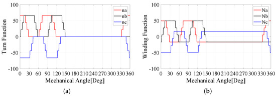
Figure 5.
ABC-phase of W1122. (a) Turn function and (b) winding function [23].
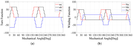
Figure 6.
ABC-phase of W1212. (a) Turn function and (b) winding function [23].
In this paper, only the fundamental component of the inductance value is considered to calculate the torque characteristics. Additionally, to evaluate the accuracy of WFT, the inductance values resulting from WFT are compared with those from the FEM.
Figure 7 shows the self-inductance and mutual inductance behaviors of the ABC-system for the W1122 model. It is shown that the mean value of self-inductance for WFT is slightly lower than that of FEM, as shown in Figure 7a. Otherwise, it is confirmed that the amplitude of the mutual inductance for WFT is similar to that of FEM, as shown in Figure 7b. In the case of the mutual inductance between the ABC- and XYZ-systems, it is shown that both the mean and amplitude values of WFT are similar to those of FEM. In particular, it is confirmed that the mutual inductances of the XYZ-system with the A-phase are relatively low compared to the self- and mutual inductances of the ABC-system, as shown in Figure 7c.
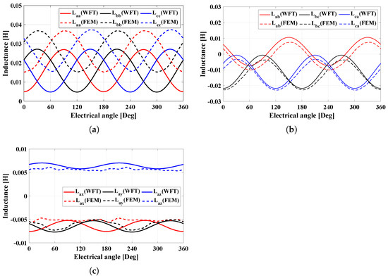
Figure 7.
Inductance behaviors of W1122. (a) Self-inductances of ABC-system, (b) mutual inductances of ABC-system, and (c) mutual inductances of XYZ-system with A-phase.
Figure 8a,b show the self-inductance and mutual inductance behaviors of the ABC-system for the W1212 model. It is confirmed that the WFT and FEM results for the ABC-system are similar to the results for W1122, but the mutual inductance between the XYZ-system and A-phase in Figure 8c is quite different from that of W1122. The mutual inductance of W1212 is higher than that of W1122. The mutual inductances are considered not only within the ABC-system, but also between the ABC- and XYZ-systems. As a result, the amplitudes of the self-inductances of the W1122 model are slightly higher than those of the W1212 model; on the other hand, the amplitudes of the mutual inductances between the ABC- and XYZ-systems of the W1122 model are somewhat lower than those of the W1212 model. This has an effect on the torque characteristic.

Figure 8.
Inductance behaviors of W1212. (a) Self-inductances of ABC-system, (b) mutual inductances of ABC-system, and (c) mutual inductances of XYZ-system with A-phase.
The difference in the inductance behaviors between the W1122 and W1212 models results in the torque characteristic, as shown in Figure 9. As a result, the total average values of both models are the same, but each value is different. The and of the W1122 model are higher than those of the W1212 model, whereas the of the W1122 model is lower than that of the W1212 model.
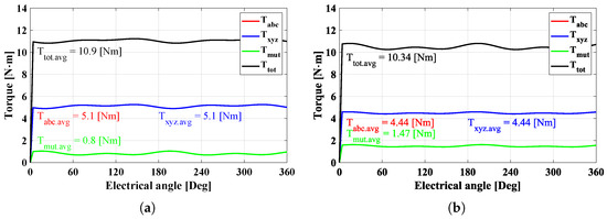
Figure 9.
Torque characteristics with 8A under normal conditions. (a) W1122 and (b) W1212.
The DT-SynRM works with two three-phase VSI systems; thus, it has a greater capability to implement various control strategies compared to three- or five-phase machines. The output characteristics of the motor can be controlled between around 50% and 100% of the rated performance by controlling only one three-phase system. This is referred to as the half-control mode (HC mode). Figure 10 shows the torque characteristics under HC mode, which fed only the ABC-phase. We consider only the torque component of the ABC-system. Therefore, the is the . As mentioned above, the W1122 model has a very similar average torque to the W1212 model.
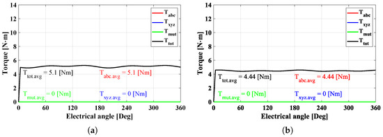
Figure 10.
Torque characteristics with 8A under HC mode conditions. (a) W1122 and (b) W1212.
4. Performance Comparison According to Barrier Design
Referring to Equation (5), the performance is affected by not only the winding and turn functions but also the inverse air-gap function. Since the inverse air-gap function is affected by the salient pole, this aspect results in the torque characteristic. Therefore, it is important to analyze the torque characteristic according to the rotor design. The air−gap length distribution of the DT-SynRM is shown in Figure 11, and it is applied to the inverse air-gap function.
Figure 11.
The air-gap length distribution.
When the rotor barrier is designed and optimized, the parameters related to the inductance between the d-axis and the q-axis are utilized [25,26,27]. In order to analyze the performance change depending on the design factor simply and quickly, the design factor k is chosen, as shown in Figure 12. In this paper, we assume that the barrier length at the d-axis and the q-axis is fixed. Only changes in characteristics according to the length and thickness of the flux path are analyzed. As shown in Figure 13, the rotor barrier is changed by the k factor. The average torque and torque ripple of the W1122 and W1212 models are compared according to the factor and control conditions.
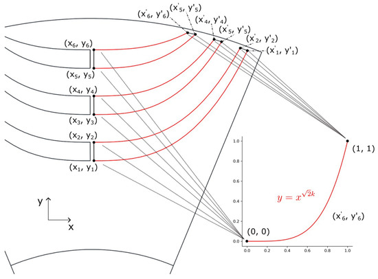
Figure 12.
The design factor of the rotor barrier.
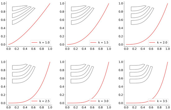
Figure 13.
The barrier design with the factor.
Figure 14 shows the comparison of the torque characteristics under normal conditions and shows the average torque and torque ripple according to the winding configuration (W1122 and W1212) with respect to the design factor k.
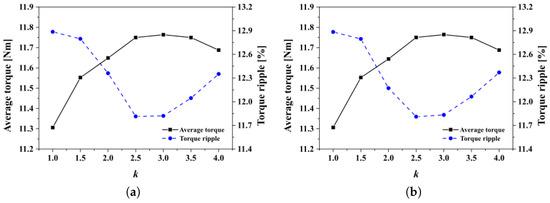
Figure 14.
The torque characteristics under normal conditions. (a) W1122 model and (b) W1212 model.
Based on the analysis results, the change patterns of the two models according to the design factor k are highly similar. More specifically, it is found that the average torque increases as the k value increases in both the W1122 and W1212 models. Additionally, it is found that the torque ripple decreases up to k = 2.5 and then increases from k = 3.
When the W1122 and W1212 models are operated under the HC mode conditions, the torque characteristics according to the factor are as shown in Figure 15.
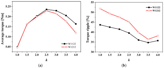
Figure 15.
The torque characteristics under HC mode conditions. (a) Average torque and (b) torque ripple.
In both the W1122 and W1212 models, it is observed that the average torque increases up to k = 2.5 and decreases thereafter from k = 3.0. Regarding the torque ripple, it decreases up to k = 3.5, after which it begins to increase again from k = 4.
Compared to normal conditions, the output characteristic of the two models changes differently depending on the factor. Therefore, when designing a DT-SynRM, which offers the advantage of being able to operate in HC mode even if one three-phase system fails, the winding configuration and rotor shape characteristics should be considered under HC mode conditions.
5. Experimental Results
A prototype is manufactured to conduct the experiment, and the experimental model is shown in Figure 16. The specifications of the motor are the same as shown in Table 1 and Table 2. The winding tap is located at the top of the motor to change the winding configuration. In order to evaluate the characteristics of the DT-SynRM according to the winding configuration and control mode, the torque characteristics of the W1122 and W1212 models are measured through an experiment.
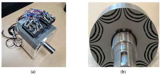
Figure 16.
Prototype. (a) Manufactured model and (b) rotor part.
Figure 17 shows the the experimental setup, which consists of the test motor, the motor for load, the DT inverter, and the dynamo setup. This study uses only one three-phase inverter, and the motor windings of the - and -systems are connected in parallel to obtain a simple experimental setup.
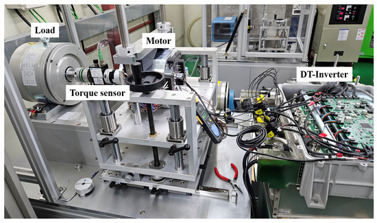
Figure 17.
Experimental setup.
Figure 18 shows the torque behaviors under normal conditions. Figure 18a shows the maximum torque per ampere (MTPA) characteristics, Figure 18b shows the torque map for various d-q currents, and Figure 18c shows the torque behavior at 8A determined by MTPA. It is verified that the average torque under normal conditions is 11.4 Nm, when the input current is 8A. When compared with the analytical results, it was confirmed that there was an approximately 10% difference in the average torque. This discrepancy arises because the exact inductance values and inverse air-gap were not used in the analysis. However, the two models under normal conditions have the same average torque behavior.
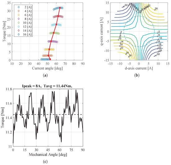
Figure 18.
Torque characteristics in experiment under normal condition. (a) Torque according to current angle, (b) Torque map for various d-q currents, and (c) Torque under normal condition.
Figure 19 and Figure 20 show the torque behaviors of the W1122 and W1212 models under the HC mode conditions. Figure 19a and Figure 20a show the maximum torque per ampere (MTPA) characteristics. Figure 19b and Figure 20b show the torque maps for various d-q currents, and Figure 19c and Figure 20c show the torque behavior at 8A, as determined by MTPA. As a result, the torque characteristics of the two models according to the current angle show different aspects. Therefore, the control method must be used differently depending on the winding configuration in the HC mode conditions. Moreover, it is confirmed that the torque of the W1122 model is still higher than that of the W1212 model, as shown in the analytical results. This means that the performance predicted via the analytical results matches with the experimental results.
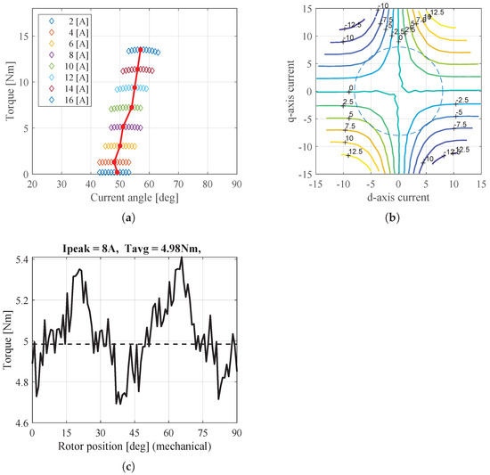
Figure 19.
Torque characteristics of W1122 model in experiment under HC mode conditions. (a) Torque according to current angle, (b) Torque map for various d-q currents, and (c) Torque under HC mode condition.
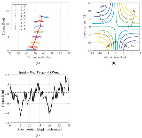
Figure 20.
Torque characteristics of W1212 model in experiment under HC mode conditions. (a) Torque according to current angle, (b) Torque map for various d-q currents, and (c) Torque under HC mode condition.
6. Conclusions
This paper analyzed the performance of a DT-SynRM according to the winding configuration under different control modes. The analysis was conducted considering not only the winding configuration but also the rotor design factor. Additionally, we evaluated the analysis results through an analytical method, a simulation, and an experiment. In the case of the DT-SynRM, the winding configuration can be composed of the W1122 and W1212 models. The torque behaviors of each model were analyzed under normal conditions and HC mode conditions. In addition, a performance comparison of the two models according to the rotor design factor was conducted. As a result, the torque characteristics obtained by the analytical method and the experiment were compared.
Overall, when the motor is operated under normal conditions, the performance of the two models according to the design factor is not different; however, in the case of the HC mode conditions, the design factor had an effect on the performance. Therefore, when designing a DT-SynRM, it is verified that the rotor shape change with each winding configuration is an important factor to consider regarding the output value.
Funding
This work was supported by the Tongmyoung University Research Grants 2021A007.
Data Availability Statement
Data are contained within the article.
Conflicts of Interest
The author declares no conflicts of interest.
References
- Yan, H.; Zhao, W.; Buticchi, G.; Gerada, C. Active thermal control for modular power converters in multi-phase permanent magnet synchronous motor drive system. IEEE Access 2021, 9, 7054–7063. [Google Scholar] [CrossRef]
- Xu, P.; Feng, J.; Guo, S.; Feng, S.; Chu, W.; Ren, Y.; Zhu, Z.Q. Analysis of dual three-phase permanent-magnet synchronous machines with different angle displacements. IEEE Trans. Ind. Electron. 2018, 65, 1941–1954. [Google Scholar] [CrossRef]
- Shah, S.H.; Wang, X.; Azeem, M.; Abubakar, U. Evaluation of magnetomotive force and torque ripples in modular type ipmsm with multi three-phase winding configurations. IEEE Access 2022, 10, 1577–1590. [Google Scholar] [CrossRef]
- Wei, Y.; Qiao, M.; Zhu, P. Fault-tolerant operation of five-phase permanent magnet synchronous motor with independent phase driving control. CES Trans. Electr. Mach. Syst. 2022, 6, 105–110. [Google Scholar] [CrossRef]
- Demir, Y.; Aydin, M. A novel dual three-phase permanent magnet synchronous motor with asymmetric stator winding. IEEE Trans. Magn. 2016, 52, 8105005. [Google Scholar] [CrossRef]
- Ding, W.; Hu, Y.; Wu, L. Investigation and experimental test of fault-tolerant operation of a mutually coupled dual three-phase SRM drive under faulty conditions. IEEE Trans. Power Electron. 2015, 30, 6857–6872. [Google Scholar] [CrossRef]
- Daniels, B.; Gurung, J.; Huisman, H.; Lomonova, E.A. Feasibility study of multi-phase machine winding reconfiguration for fully electric vehicles. In Proceedings of the IEEE Fourteenth International Conference on Ecologicall Vehicles and Renewable Energies, Monte-Carlo, Monaco, 8–10 May 2019. [Google Scholar]
- Pescetto, P.; Cruz, M.F.T.; Stella, F.; Pellegrino, G. Galvanically isolated on-board charger fully integrated with 6-phase traction motor drives. IEEE Access 2023, 11, 26059–26069. [Google Scholar] [CrossRef]
- Chen, W.; Zhu, L.; Li, X.; Shi, T.; Xia, C. Comparing the performance of parallel multi-phase brushless dc motors: A comprehensive analysis. IEEE Trans. Power Electron. 2023, 38, 11290–11303. [Google Scholar] [CrossRef]
- Boglietti, A.; Bojoi, R.; Cavagnino, A.; Tenconi, A. Efficiency analysis of pwm inverter fed three-phase and dual three-phase high frequency induction machines for low/medium power applications. IEEE Trans. Ind. Electron. 2018, 55, 2015–2023. [Google Scholar] [CrossRef]
- Hu, Y.; Zhu, Z.Q.; Liu, K. Current control for dual three-phase permanent magnet synchronous motors according for current unbalance and harmonics. IEEE J. Emerg. Sel. Top. Power Electon. 2014, 2, 272–284. [Google Scholar]
- Yolacan, E.; Guven, M.K.; Aydin, M.; El-refale, A.M. Modeling and experimental verification of an unconventional 9-phase asymmetric winding pm motor dedicated to electric traction applications. IEEE Access 2020, 8, 70182–70192. [Google Scholar] [CrossRef]
- Liang, Z.; Liang, D.; Kou, P.; Jia, S. Postfault control and harmonic current suppression for a symmetrical dual three-phase SPMSM drive under single-phase open-circuit fault. IEEE Access 2020, 8, 67674–67686. [Google Scholar] [CrossRef]
- Onsal, M.; Demir, Y.; Aydin, M. A New nine-phase permanent magnet synchronous motor with consequent pole rotor for high-power traction applications. IEEE Trans. Magn. 2017, 53, 8700606. [Google Scholar] [CrossRef]
- Sun, X.; Xu, N.; Yao, M. Sequential subspace optimization design of a dual three-phase permanent magnet synchronous hub motor based on nsga iii. IEEE Trans. Transp. Electrif. 2023, 9, 622–630. [Google Scholar] [CrossRef]
- Wang, W.; Zhang, J.; Cheng, M.; Li, S. Fault-tolerant control of dual three-phase permanent-magnet synchronous machine drives under open-phase faults. IEEE Trans. Power Electron. 2017, 32, 2052–2063. [Google Scholar] [CrossRef]
- Tessarolo, A. Accurate computation of multiphase synchronous machine inductances based on winding function theory. IEEE Trans. Energy Convers. 2012, 27, 895–904. [Google Scholar] [CrossRef]
- Kim, K.; Park, J.; Hur, J.; Kim, B. Comparison of the fault characteristics of IPM-type and SPM-type BLDC motors under inter-turn fault conditions using winding function theory. IEEE Trans. Ind. Appl. 2014, 50, 986–994. [Google Scholar] [CrossRef]
- Rezaeealam, F.; Rezaeealam, B.; Naeini, V. An improved winding function theory for accurate modeling of small and large air-gap electric machines. IEEE Trans. Mag. 2021, 57, 8104513. [Google Scholar]
- Li, Q.; Fan, T.; Wen, X. Armature-reaction magnetic field analysis for interior permanent magnet motor based on winding function theory. IEEE Trans. Mag. 2013, 49, 1193–1201. [Google Scholar] [CrossRef]
- Ge, B.; Liu, W.; Dong, J.; Liu, M. Extending winding function theory to incorporate secondary effects in the design of induction machines and drives. IEEE J. Emerg. Sel. Top. Power Electron. 2022, 10, 1915–1924. [Google Scholar] [CrossRef]
- Gao, Y.; Qu, R.; Li, D. Improved hybrid method to calculate inductances of permanent magnet synchronous machines with skewed stators based on winding function theory. Chin. J. Electr. Eng. 2016, 2, 52–61. [Google Scholar]
- Jeong, C.; Park, J.; Bianchi, N. Analysis of dual three-phase synchronous reluctance motor by winding function theory. In Proceedings of the 2020 International Conference on Electrical Machines, Gothenburg, Sweden, 23–26 August 2020. [Google Scholar]
- Park, J.; Babetto, C.; Berardi, G.; Hur, J.; Bianchi, N. Comparison of fault characteristics according to winding configurations for dual three-phase synchronous reluctance motor. IEEE Trans. Ind. Appl. 2021, 57, 2398–2406. [Google Scholar] [CrossRef]
- Moghaddam, R.; Gyllensten, F. Novel high-performance synrm design method: An easy approach for a complicated rotor topology. IEEE Trans. Ind. Electron. 2013, 61, 5058–5065. [Google Scholar] [CrossRef]
- Chowdhury, M.; Tesfamicael, A.; Islam, M.; Husain, I. Design optimization of a synchronous reluctance machine for high-performance applications. IEEE Trans. Ind. Appl. 2021, 57, 4720–4732. [Google Scholar] [CrossRef]
- Credo, A.; Fabri, G.; Villani, M.; Popescu, M. A robust design methodology for synchronous reluctance motors. IEEE Trans. Energy Convers. 2020, 35, 2095–2105. [Google Scholar] [CrossRef]


Disclaimer/Publisher’s Note: The statements, opinions and data contained in all publications are solely those of the individual author(s) and contributor(s) and not of MDPI and/or the editor(s). MDPI and/or the editor(s) disclaim responsibility for any injury to people or property resulting from any ideas, methods, instructions or products referred to in the content. |
© 2024 by the author. Licensee MDPI, Basel, Switzerland. This article is an open access article distributed under the terms and conditions of the Creative Commons Attribution (CC BY) license (https://creativecommons.org/licenses/by/4.0/).