Abstract
Wireless technologies are revolutionizing communications, with recent deployments, such as 5G, playing a key role in the future of the Internet of Things (IoT). Such progress is leading to an increasingly higher number of wirelessly connected devices. These require increased battery use and maintenance, consequently straining current powering solutions. Since most wireless systems rely on radiofrequency (RF) waves for communications and feature low-power technologies, it is increasingly feasible to develop and implement wireless power transfer solutions supported by RF. In this paper, a simultaneous wireless information and power transfer (SWIPT) solution targeting small mobile devices is presented. This solution uses beamforming to mitigate the path loss associated with the RF power propagation. It relies on an RF backscattering tracking algorithm to power moving devices. The feasibility to power wearable devices is demonstrated by tracking a walking individual (approximately 5 km/h) at a distance of 0.5 m while transferring a minimum of 6 dBm to a wearable device using 2 GHz RF signals. Simulations were used to determine the viability of such a solution to deliver useful power levels to a 1.2 × 1.4 m2 working area without exceeding specific absorption rate (SAR) limits.
1. Introduction
Technological developments in wireless cyber–physical devices promote the interconnectivity of everything, everywhere, all the time. They are key for the advancement of global economy and everyone’s lifestyle and quality of life. The recent deployment and commercial adoption of the 5G network is a further step toward increased connectivity that positively impacts the world. It promises to provide lower latency and faster connections, changing the way we use wireless links, which will ultimately be a key technological enabler for the Internet of Things (IoT) [1,2].
According to [3], wireless network design is calling for a rethinking. The power required for a given computing task will decrease by a factor of 10.000 in the time frame of 20 years [3]. Thus, it is expected that a swarm of low-power devices will be incorporated in communication networks. Since wireless sensor networks (WSNs) have an important role in monitoring, tracking, and data collection, it is also becoming increasingly important to tackle the power demands in those networks. Furthermore, there are sensors being developed with wireless communication, and energy harvesting could benefit from wireless powering [4,5,6,7]. However, powering tiny modules, especially if they are mobile, is still a challenge [8,9,10,11]. With this scenario in perspective, methods to obtain a perpetual wireless powered communication are still being pursued [9,12,13,14,15], with the mobile solutions being the most challenging.
The electromagnetic signals used in radiofrequency (RF) communication links may transport both information and power over long distances. Consequently, it becomes appealing for some applications since by further increasing the base station transmitted power, it may be possible to design the mobile device to use that extra power as its own energy source. In some cases, by slightly modifying wireless systems, it should be possible to obtain a simultaneous wireless information and power transfer (SWIPT) link [3,9].
Current engineering solutions have allowed for the development of low-power wireless sensors and WSNs, which have a wide range of applications such as military, agricultural, environmental, and human-centric applications [1,16]. Wireless power transfer (WPT) for IoT devices can further extend the potential of available wireless technologies and become a technological key enabler for a multitude of applications. This may be supported by the development of SWIPT solutions for some of those applications.
For agricultural applications, we have the example of wine production. It is a process so complex that even controlling the grape maturation and harvesting is a monitoring challenge, which is currently being tackled [17]. A possible solution is building fixed SWIPT base stations along the vineyard, with steering beams to read sensors that are scattered randomly every year. The other option would be the use of an autonomous rover that moves along the vineyard with a SWIPT that scans each sensing module. In this way, the sensing modules would not need any battery, increasing their disposability, reducing maintenance costs and, in some cases, allowing for smaller modules that can fit inside a single grape. For logistics, SWIPT may enable a cost reduction in identification tags, as well as their disposal impact, by removing or reducing the battery needs. In some cases, it would also allow for the deployment of more complex tags, since the required additional power would be delivered through the wireless link. It would also enable increased functionality, like control of the temperature of the inventory during transport [18], allowing it to increase the shelf life of perishable food products.
Another well-known and highly researched application is the field of wearable solutions. It is possible to find proposals using very low power, such as e-skin sensors for wearable biomedical applications [19], or graphene wireless nanosensors [20]. These devices have a power consumption in the µW range, with the authors in [5] claiming that a power transmission of −16 dBm would enable continuous operation of their device. This means that with the right configuration, it could be possible to achieve the desired SWIPT link for these devices and may open the path for the development of similar ones. Another example of an application that would benefit from far-field WPT is the e-tattoo biosensor proposed in [21]. Instead of establishing a readout using a short range near-field communication (NFC) connection, it would be possible to do it with a far-field device. Such readers can be placed in the person’s vehicle or in the household, where the sensor readout would occur automatically and without hassle to the user.
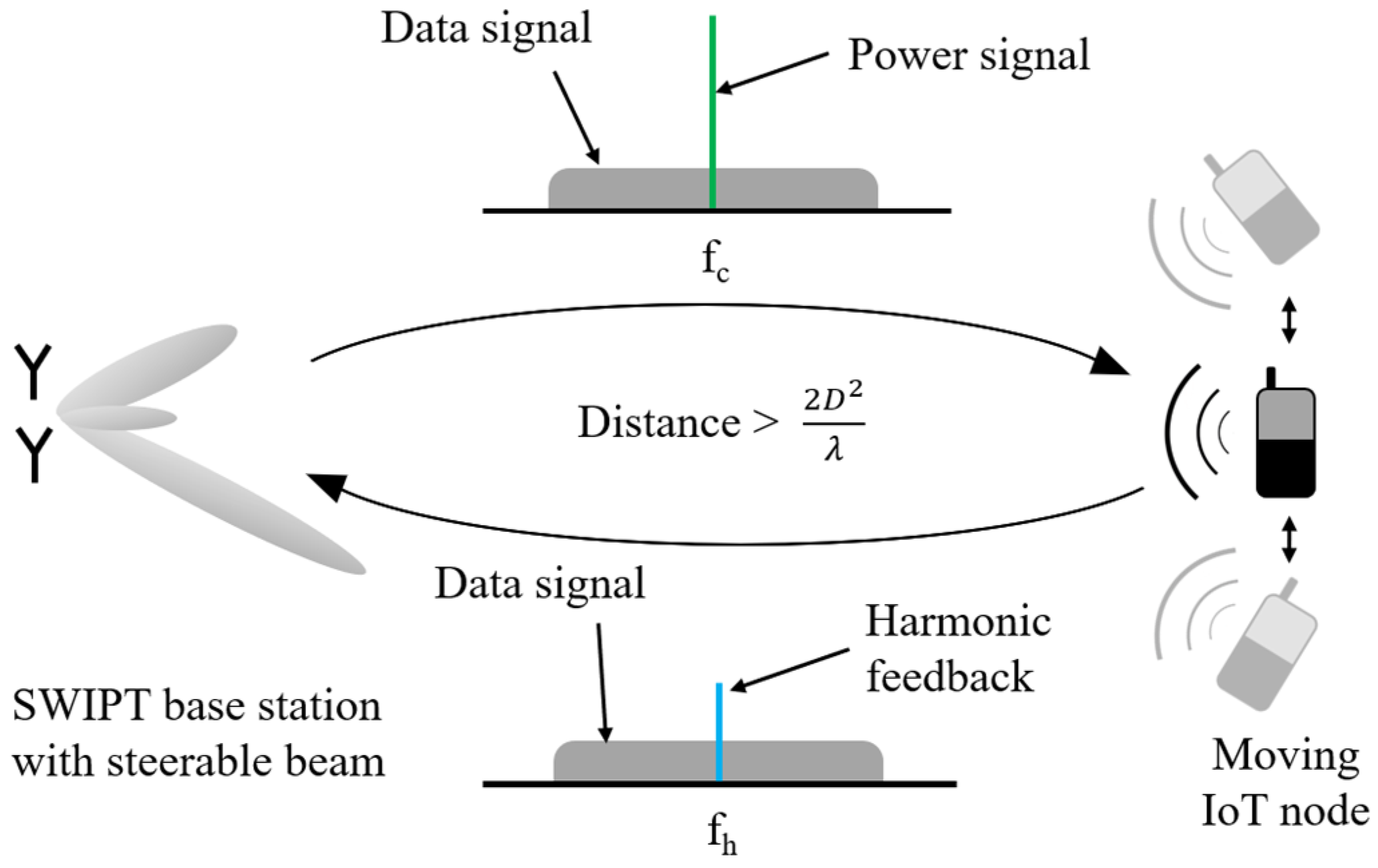
This work proposes a solution to tackle the wireless powering of IoT nodes that may be scattered in random locations, or even to be used on moving individuals or platforms. There are various types of SWIPT methods but, since the power-splitting technique is recognized as the best trade-off between information rate and amount of power transfer [9,22], it was used in this work. We report on a steerable continuous wave (CW) RF link that relies on a harmonic power feedback to implement the WPT sub-system of a SWIPT system. The performance and specific absorption rate (SAR) values are analyzed and compared to the traditional one-antenna scenario through simulations. Since current sensors can already relay information when interrogated by an external device, this work focuses on the powering link. Therefore, it is considered that the sensor’s data are mixed with the harmonic power feedback signal, thus modulating both sensor data and powering link performance through the harmonic feedback [23], as exemplified in Figure 1. For the case of passive sensors, these are based on LC resonators [24,25,26,27], in which the monitored parameter is translated into a shift in the resonant frequency, thus making it a simple implementation.

Figure 1.
Proposed SWIPT scheme with data transfer and harmonic powering feedback.
2. SWIPT System Design
To help tackle the intrinsic low efficiency of RF links for long distances, increase the amount of power transferred, and allow beam steering, the WPT solution selected was based on the use of an antenna array. This way, it was possible to transmit the power in the required direction through beamforming. Furthermore, since it is expected that the adoption of this system will lead to a reduction in battery size, or even a removal of this element, a backscatter-like communication should be implemented. This implies that low power levels will be used. These conditions and limitations, along with the previously defined applications–which are in the short- to mid-range–establish a working range of the few centimeters to meters, depending on the application and its specific power constraints.
Most applications can have their moving velocity controlled and can have a slow to medium moving speed, such as the velocity of a walking human. Thus, the tracking velocity was defined to be at least 5 km/h. Another requirement of the tracking system is the need to locate the target sensor/device, since in most applications the initial relative location of the devices is unknown. Finally, it is necessary to define the power level that may be simultaneously able to deliver enough power to the node and is transmissible by available technology. Looking in the literature, it is possible to find wireless sensors work in the nW to the µW range [4,5,6,7], which allows us to define that, at least for these examples, the minimum transmitted power should be −16 dBm, since it is the highest power level requirement for the continuous powering of such devices.
For some applications, it is only necessary to transmit power for some period and, after that, the data readout is received. In that case, a single antenna system is enough. For applications that may require continuous powering and tracking, the positional data from the remote device should be transferred to the powering system, so that tracking and powering can be achieved. Despite not being mandatory, the proposed solution for these requirements is a dual-band system. One frequency band can be used for powering and forwarding data communications with the device, and the other band can be used for feedback tracking of the IoT node position and sensor backward data readout. This allows for the communication protocol’s complexity to be reduced, which can help in the device design. Furthermore, it results in a system that can have continuous power transfer and real-time tracking, while maintaining a data transfer link with less complexity. The main disadvantage is the need for a dual-band antenna system.
2.1. Proof-of-Concept IoT Device Design
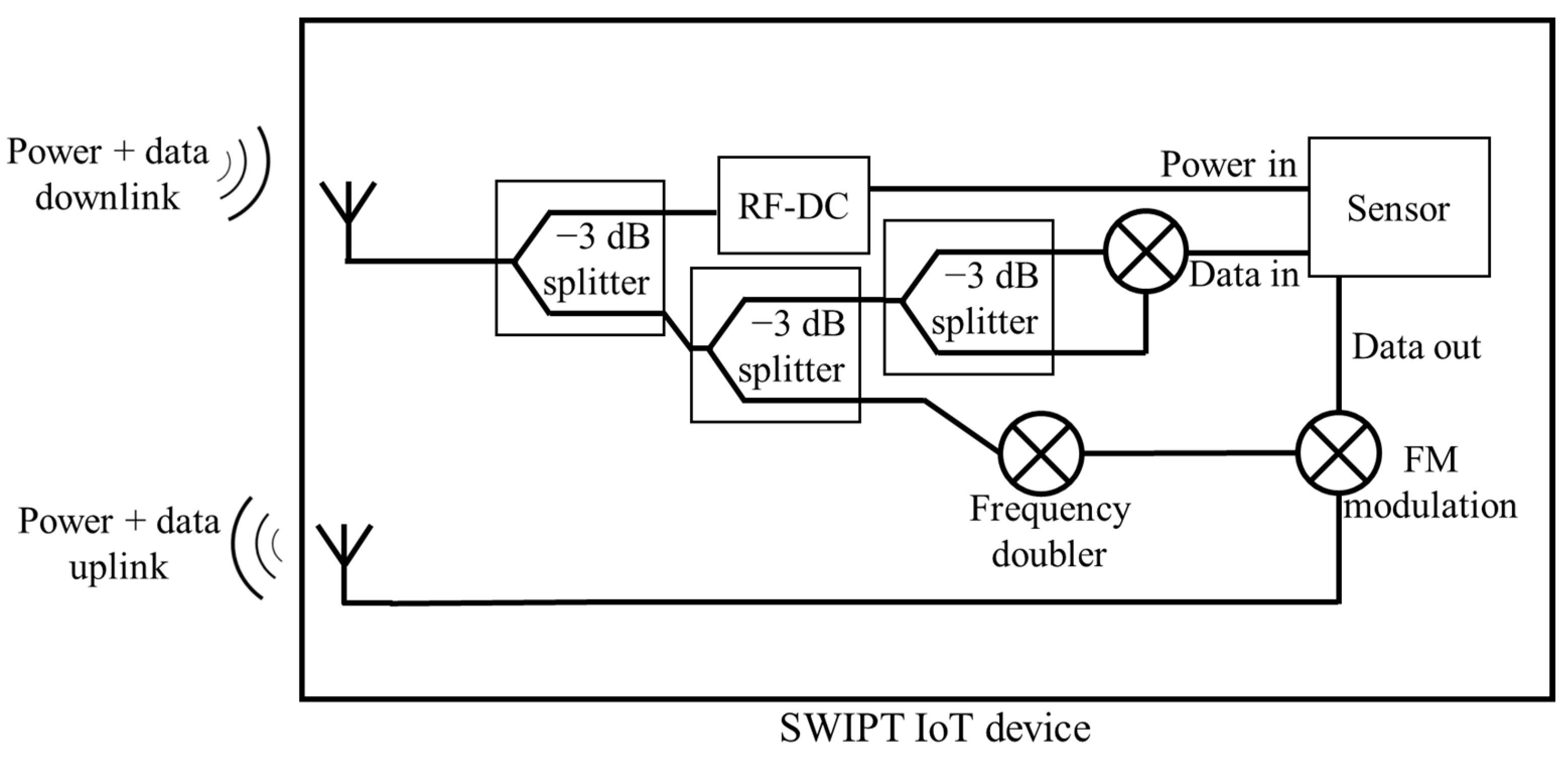
An IoT sensor compatible with dual-band SWIPT technology would rely on backscatter readout, where the backscattered wave may be modulated according to, e.g., some biomolecule concentration. A possible architecture of such is exemplified in Figure 2. For this device, it is necessary to have a biosensing element, a WPT link where the receiver can harvest the power from the external powering link, and a modulation scheme for the data to be wirelessly transmitted. Its principle of operation can be divided into two moments: downlink and uplink. In the downlink, the device receives the electromagnetic waves sent by an exterior unit. From these, the device must extract energy to operate and be able to transmit the sensor readings. So, the signal is split in half in the first 3 dB splitter. The first half is sent to the RF-DC block, to extract energy for the device’s operation. The second half is then split again and directed to a mixer where it is demodulated by itself, allowing one to extract the downlink data. The second moment of operation consists in transmitting the data from the sensor. For this, the second half of the signal obtained from the splitter in the middle is directed to a frequency doubler and is then used to modulate the sensor data and transmit it through the antenna.
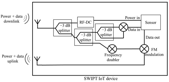
Figure 2.
IoT device electronics for wireless powering and data readout.
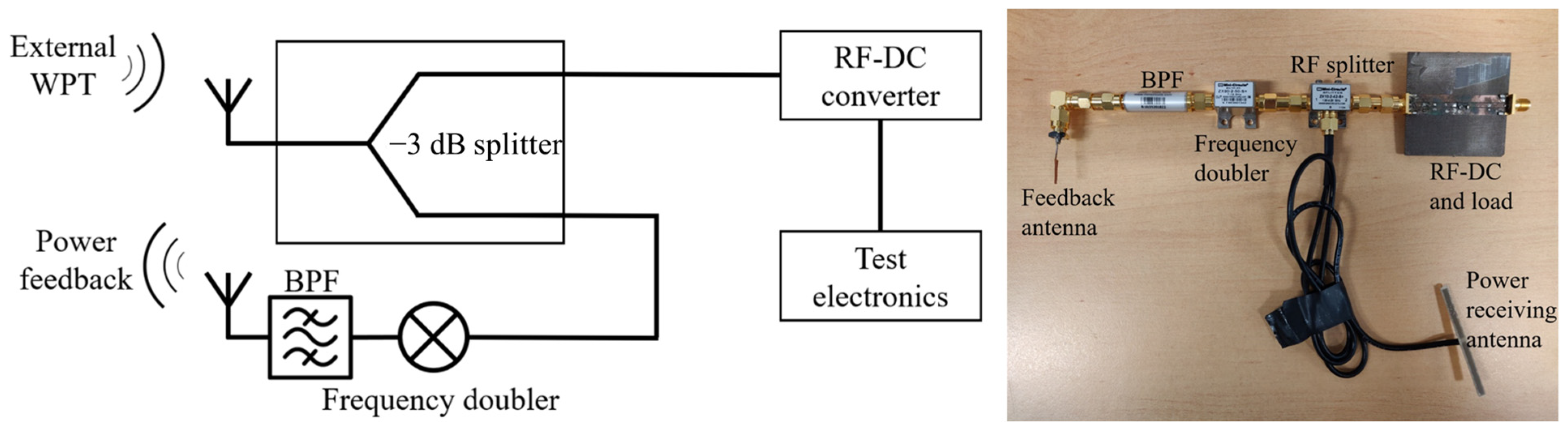
As previously mentioned, this work will focus on the WPT aspect of the problem, as the backscattering modulation of sensor data is an established application. The ability to deliver an effective amount of power as the device moves is a challenge to be tackled. The device proposed in this work, whose block diagram is presented in Figure 3, contains a light-emitting diode (LED) in the “test electronics” block, and its brightness provides feedback on the power level being received. Given that this device is desired to be completely battery-free, a 2 GHz link was used for the external WPT. Through a splitter, half of the received power is directed to the RF-DC converter, which then powers the LED. The other half is directed to a frequency doubler to provide a received power level feedback for the external system (which could also be used to backscatter the biosensor information, as shown in the block diagram of Figure 2).
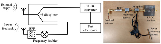
Figure 3.
Block diagram and photograph of the developed system to provide wireless feedback of the power transferred.
2.2. WPT System Design
The system was based on the concept of multiple transmitters, or antenna arrays, to increase the antenna gain, and to allow some degree of beam steering [28]. It allows for active tracking to be used, providing a system that can transfer power to a moving target.
When a phased array concept is used, its directivity is defined by multiplying the array factor with the directivity of the individual elements:
where the directivity of the element is inherent to its own characteristics, and the array factor (AF) can be controlled through the array’s excitation. For two elements, it is defined as follows:
where its value can be controlled through , which is the distance between the array’s elements, and through , which is excitation phase difference, when considering equal excitation magnitudes. It is possible to conclude that by controlling the excitation phase difference, it is possible to control the array’s characteristics and increase its directivity in the desired direction.
In the developed WPT system, an antenna array composed of two elements operating at 2 GHz was chosen, with a spacing of . More complex systems with larger antenna arrays can be developed, albeit with higher computational requirements and cost. For technological demonstration purposes, a two-element array suffices. The electronics and RF circuitry were deployed so that both antennas transmit the same power, and the excitation phase difference can be dynamically controlled, allowing it to power the proposed moving wireless device.
2.2.1. WPT Hardware
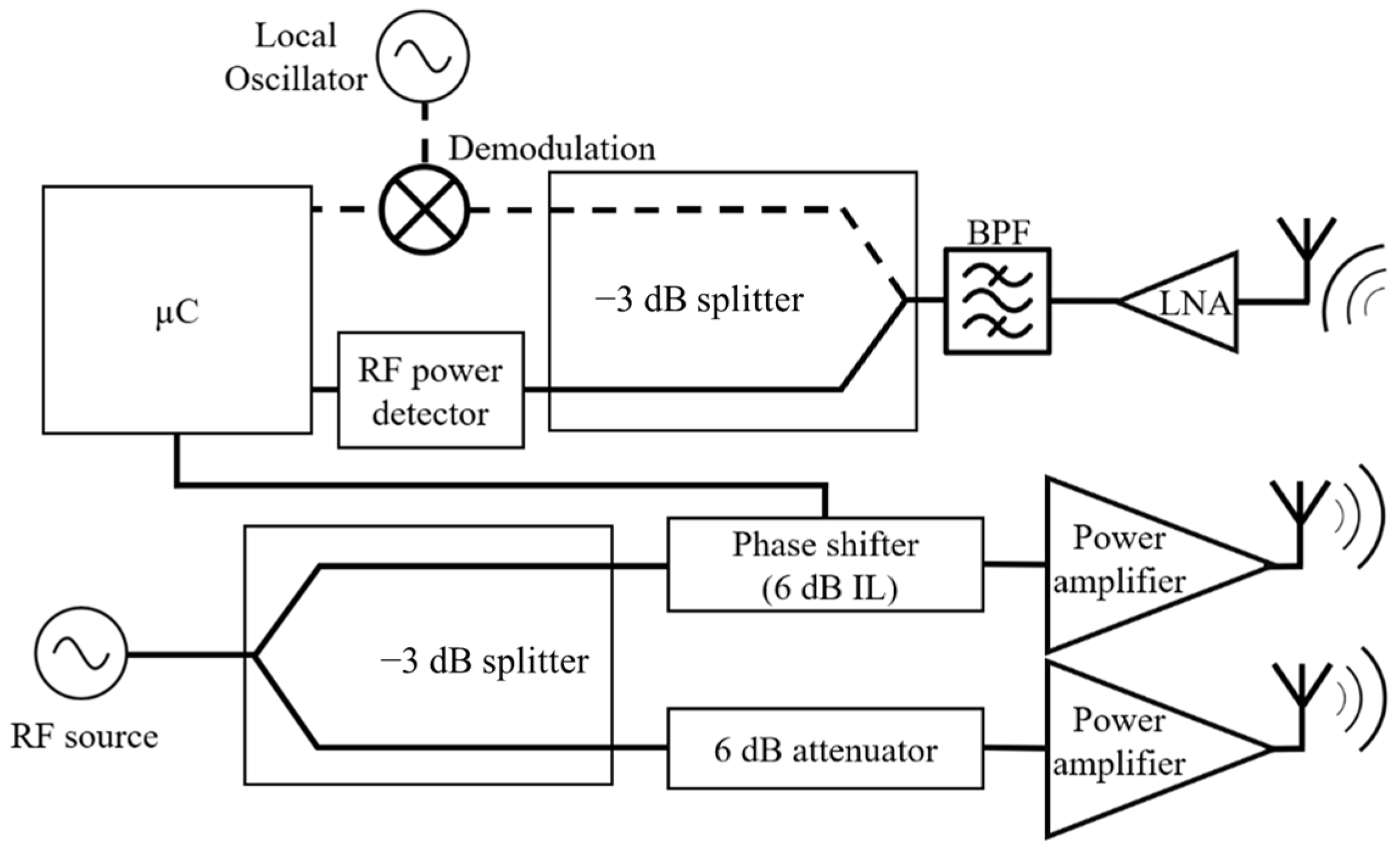
The objective of establishing a WPT link with a mobile IoT module and reading the incoming signals requires an RF base station with two main functions: wireless power transmission, and incoming signal reception (with information from a sensor and received power for purposes of a tracking algorithm). The desired system for SWIPT and data readout is proposed in Figure 4.

Figure 4.
Proposed system for SWIPT and wireless IoT module feedback readout.
The proposed WPT system was subdivided into two parts: transmission and feedback handling. The transmission requires two RF signals with a controlled phase difference. This is achieved through an RF source and a splitter with low amplitude and phase unbalance. Then, one of the RF signals will have its phase modified through a phase shifter, while the other signal is attenuated 6 dB to compensate the phase shifter’s insertion loss. After the desired phase difference is obtained, these signals are then amplified through two 10 W RF power amplifiers which feed the antenna array.
The power is transmitted to the mobile system presented in Figure 3, which uses part of the power for powering the device, and backscatters part of it at twice the original frequency. This signal is then received by the feedback antenna, amplified, and filtered. It is guided to a power detector, which in turn outputs an analog signal that is representative of the amount of power that is being transferred to the IoT device. This information is then used by the microcontroller to determine the correct phase difference for the two-element antenna array. Through an algorithm, it is possible to follow the mobile device and transfer power to it.
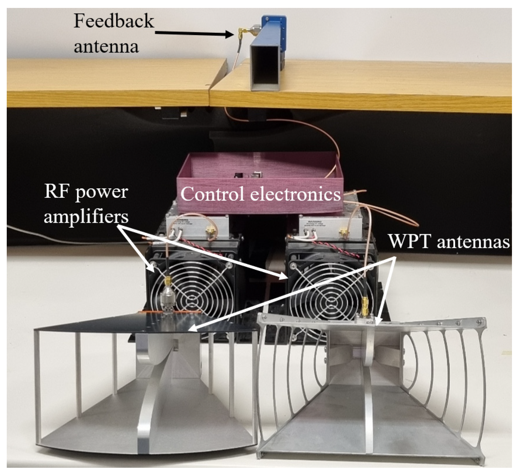
To implement this system, an Arduino Uno was used for the algorithm, to read the feedback and control the wireless transmission of power. To generate the two required RF signals, a ZX95-3800A+ voltage-controlled oscillator (VCO) was used, along with a ZAPD-2-282-S+ splitter, from MiniCircuits®. To control the phase difference, a Peregrine Semiconductor PE44820 was used, along with two VAT-3+ attenuators from MiniCircuits®. For the signal detection, a bandpass filter VBFZ-2000-S+ was used along with a ZX47-60-LN-S+ power detector, from MiniCircuits®. For the transmission of the signals, two MiniCircuits® ZHL-10W-2G+ power amplifiers were used, along with the following antennas: Pasternack PE9887-11 and MVG EH118. For the signal detection, the antenna was a Pasternack PE9821. A photograph of the system is presented in Figure 5, and it demonstrates the arrangement of the WPT antennas and the feedback antenna in cross-polarization for reduced interference.
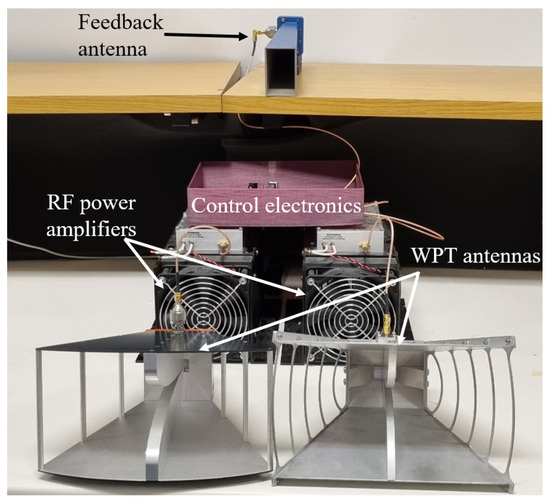
Figure 5.
Developed WPT system, with the control electronics, power amplifiers, and feedback and WPT antennas.
2.2.2. Control Software
To enable the WPT system to successfully transfer energy to the IoT device, it needs to be able to track it. To achieve this, the microcontroller must control the phase-shifter’s phase, in order to obtain the desired phase excitation difference, achieving the required beam direction. In this proposal, such tracking was achieved using only the power level of the feedback signal. Since this signal’s power is directly proportional to the transmitted power, it mirrors the power transfer efficiency variation over time. Through this information, it is possible to modify the phase excitation difference and control the amount of power transferred. An algorithm was developed so that the tracking could be performed automatically.
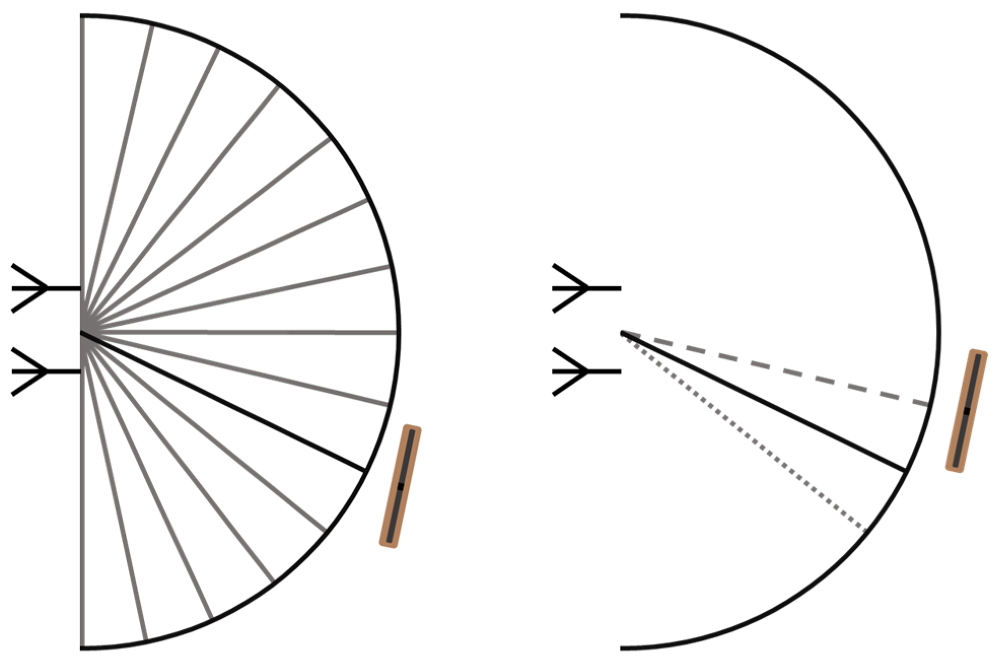
In Figure 6, both phases of the implemented algorithm are represented. On the left the cold-start brute force approach is demonstrated, where all phases are swept, covering all possible locations of the device. This sweep is represented in gray, and when it is completed and the maximum power transfer is detected (represented in black), it shifts to active tracking mode. This mode is based on the Hook and Jeeves direct search method, which is simple, derivative-free, convergent, and does not require high computing power [29]. In this case, fixed steps of 5.6° of excitation phase difference were used. The algorithm uses the current excitation phase difference, and then measures and compares the power transfer efficiency when 5.6° are added and subtracted to it. Whichever is larger is maintained, and the same procedure is repeated continuously, tracking the target. The active tracking mode refreshes up to 1000 times every second. In the example in Figure 6, the wearable device moved slightly counterclockwise, so the dashed line achieved a higher power transfer than the dotted line and the previous beamforming state (solid line). Thus, it would be selected for the power transfer and used for the next iteration’s initialization.

Figure 6.
Diagram with the two main phases of the implemented algorithm, where the brute force is shown on the left and the active tracking is shown on the right to have located the target. The dashed and the dotted lines represent the two directions adjacent to the current one (solid line) where the algorithm searches for the target.
2.2.3. Tracking System Validation
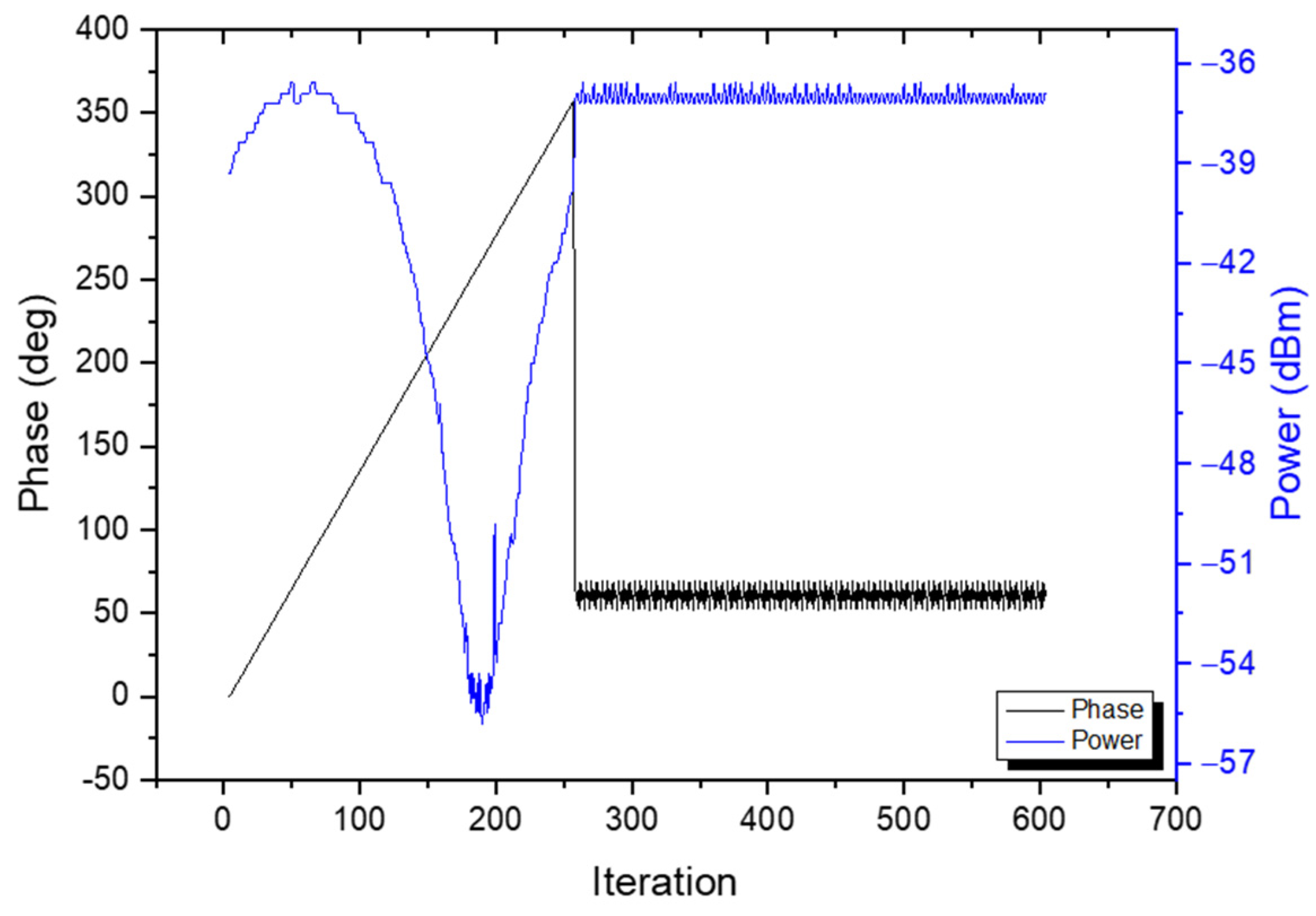
The WPT system’s tracking algorithm was initially validated on a controlled and simplified environment [30]. The feedback link was established through a coaxial cable to obtain an interference-free readout, so that the stability and tracking measurements could be performed. Figure 7 shows the results of the stability test and demonstrates the brute force and the tracking stages. The brute force stage, as previously explained, sweeps the phase difference between the two transmitters, and the received feedback power changes accordingly, as seen in the left side of Figure 7. Having determined the phase difference that delivers the highest power to the device, the tracking stage begins. The system achieved a power variation of 0.6 dBm when the target was stationary, which is a downside of the iterative nature of the algorithm. However, the small variation is worth the low computational expense of the algorithm, especially when considering that it can be reduced by using phase shifters with higher resolution.
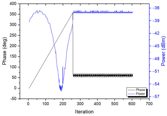
Figure 7.
Power level and excitation phase difference throughout the stability test with the receiver being stationary.
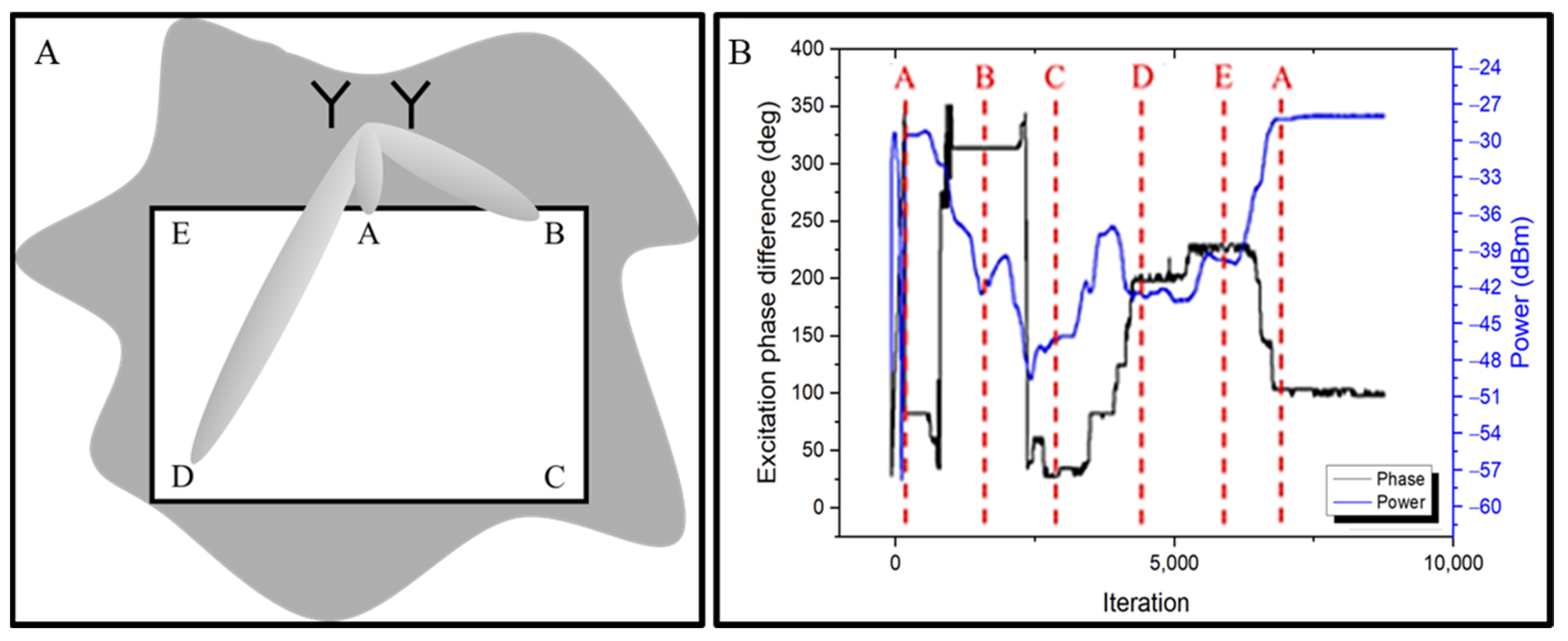
To demonstrate the tracking capabilities of the WPT system, a working area of 20 × 47 cm2 was established. The environment surrounding that area was uncontrolled, meaning that there could be interference from the outside. Inside that area, five locations were used, and the receiving antenna was moved through them in alphabetical order, starting in position A and returning to the same initial position after E. Figure 8A shows the arrangement of those locations. Figure 8B shows the resulting phase and power that the WPT system transmitted. As the IoT device moves through the marked locations, the excitation phase difference keeps being adjusted in order to maximize the power transmitted to it. As expected, due to the longer distance between the WPT system and the IoT device, the received power is lower in points C and D, and both the power level and phase return to their original values when the object returns to A. Ideally, the power delivered to the moving device would be constant at the maximum value; however, this is not possible since the distance between the transmitters and the device varies along the test. With these results, the tracking algorithm and the WPT system were validated.
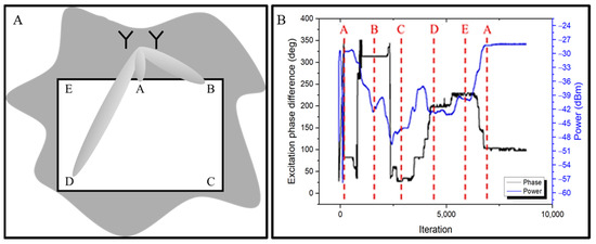
Figure 8.
Representation of the movement testing area, where the target device started and finished in position A, moving in alphabetical order through the marked locations (A), and the obtained power and phase results (B).
3. Performance Assessment of WPT Link
The demonstration IoT device presented in Figure 3 was attached to a volunteer’s arm, thus emulating a wearable sensor. The volunteer moved in front of the WPT system, and the tracking capabilities were observed. Given that in a real scenario the subject would be wearing the IoT device, the wireless powering effect on biological tissue should be assessed. In this context, certain regulations must be met. The limits for the SAR10g are 2 W/kg, while in controlled environments this limit is 10 W/kg [31].
The model was implemented using Ansys HFSS, and it consists of a phantom that moves in a defined area to mimic the movement of a real subject wearing the wireless module. Figure 9 shows the implemented simulation setup, where a two-element antenna array, with λ/2 spacing, is placed 0.3 m from the body phantom. To resemble the scenario where a person wears a wireless IoT device, the receiving antenna was placed at the surface of the phantom. It has a dielectric constant of 53.3, a conductivity of 1.52 S/m, and measures 150 × 100 × 95 mm3 [32]. The power level delivered to the antenna was monitored using the Poynting vector magnitude, which was calculated inside a rectangular area (10 mm × 10 mm) in the receiving antenna’s location. Both the phantom and antenna were then moved along a 1.5 m × 1.2 m area, with 50 mm steps. The power density and SAR values were measured in each position, considering a transmission power of 20 W for the 1 antenna scenario and 10 W for each antenna for the two-antennas scenario.
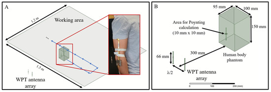
Figure 9.
Setup of the HFSS simulation; (A) shows the simulation area and the location of the antenna array, and in (B) the dimensions are disclosed.
3.1. Power Distribution Results
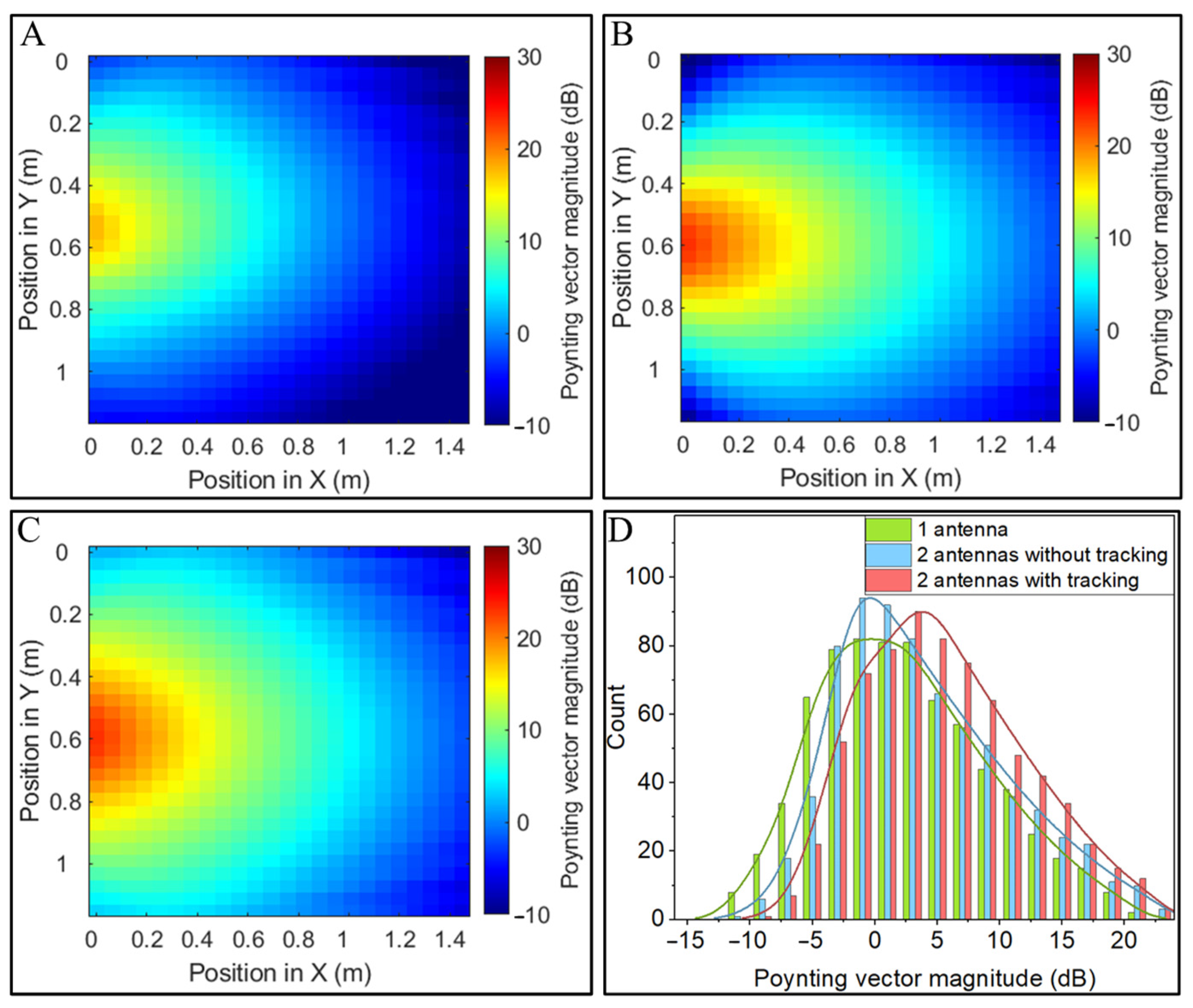
The power inside the test rectangle (10 mm × 10 mm) was measured in several positions over the 1.5 m × 1.2 m area. Figure 10 shows the results of the simulations, and the histograms facilitate the analysis of the different scenarios. The values represented in Figure 10A–C were determined by calculating the logarithm of the Poynting vector magnitude. Then, Figure 10D shows a histogram of the power transfer achieved in the different scenarios. Table 1 shows the average and median power transfer results. It shows that when comparing the scenario of one antenna with the scenario of two antennas without tracking, an average power increase of 1.5 dB, with a median of 1 dB, is expected. When comparing the one-antenna scenario with the two antennas with tracking, a higher power is achieved, with a difference of 3.18 dB on average, and 3.08 dB median. Finally, when comparing the two-antennas scenario with and without power tracking, it is possible to observe that an average increase of 1.67 dB can be achieved, with a median of 2.08 dB.
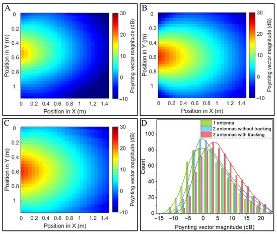
Figure 10.
Mapping of the power delivered to the wireless device in each position of the test area. (A) Single transmitter; (B) two transmitters without tracking; (C) two transmitters with tracking; (D) power transfer histograms.

Table 1.
Average and median values for the power and SAR distributions in the three scenarios: 1 antenna, 2 antennas without tracking, 2 antennas with tracking.
Therefore, it is possible to conclude that the two-antennas scenario with tracking is the most advantageous one. It not only increases the amount of power transfer when compared to the one-antenna scenario, but also increases the area of effective power transfer when compared with the two-antennas without tracking.
3.2. SAR Results
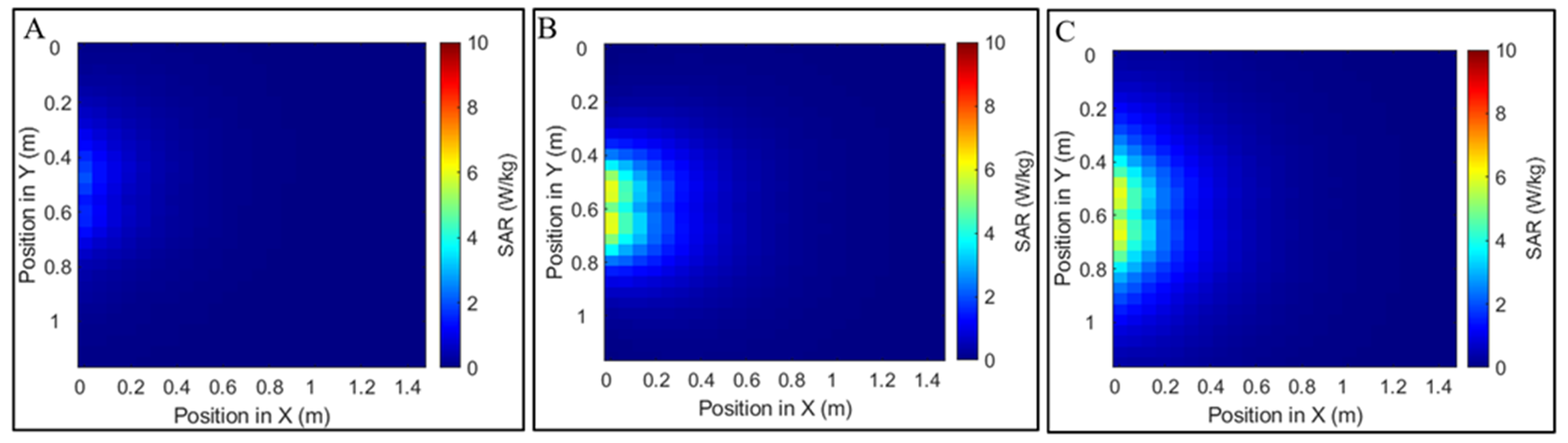
Figure 11 shows the results of the SAR simulations, where the maximum value of the SAR10g was calculated in each position. It shows the three different scenarios: one antenna (A), two antennas without tracking (B), and two antennas with tracking (C). It is possible to observe in Figure 11B,C that by adding a second antenna to the scenario, the SAR10g increases. Even though the total power being radiated by the WPT system is the same, the higher directivity resulting from the use of an antenna array increases the SAR in the biological tissue, as power is more directed towards it rather than spreading over space. In both cases where tracking is enabled or disabled, the maximum SAR value is approximately the same, meaning that the tracking algorithm does not aggravate the SAR. It was ultimately demonstrated that with the simulated 20 W scenario, the 10 W/kg SAR limit is not surpassed. Therefore, an experimental setup replicating this simulation would be safe for humans.
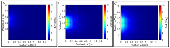
Figure 11.
Results of the maximum SAR10g value for each position in W/kg. (A) The case of 1 antenna; (B) the case of 2 antennas without tracking; (C) the case of 2 antennas with tracking.
3.3. Real Scenario Application
After concluding that the SAR limit would not be exceeded, the setup was implemented to assess the WPT system operation in conditions mimicking a real scenario. To determine whether the proposed system can be used for WPT in applications such as IoT wearable devices, an experiment with the developed systems was conducted. The results of this experiment are shown in Figure 12, where a walking subject with the receiving circuit at approximately 0.5 m from the WPT system was used to demonstrate that WPT with tracking can be achieved.
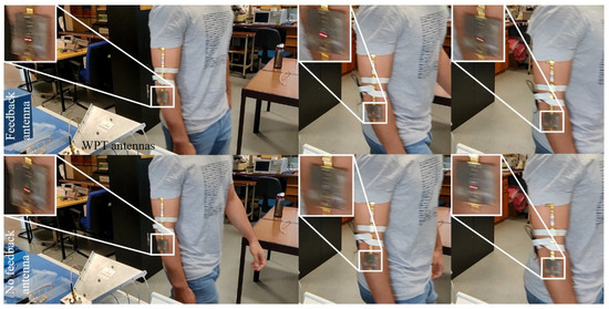
Figure 12.
Moving subject in front of the WPT system with the feedback turned on (top) and turned off (bottom).
It is possible to observe two scenarios: one where the feedback antenna was pointed to the area where the subject would cross (top), and another where the feedback antenna was removed, thus breaking the feedback loop for the tracking (bottom). It is possible to observe that when the feedback was implemented, the LED was turned on throughout the powering area. When it was turned off, the WPT became unreliable, with the LED turning off in several locations within the powering area, demonstrating the correct operation of the proposed system. Furthermore, it was demonstrated that the previously established requirements are met. The tracking system can achieve a continuous power transfer of at least 6 dBm (the minimum power level required to turn on the LED) while respecting safety limits, which are well above the −16 dBm power demand target identified in the previous section. It can also track a moving device at human walking speed and can establish a powering link in the range of a few centimeters. The use of a WPT array with additional elements would increase the power transferred to the wearable device. This would allow increased operation distance and more reliable feedback implementation due to the higher power level. However, this would come at the cost of higher computation power, as a brute force approach with additional variables is more complex. As such, alternative algorithms would have to be explored and experimented with. Additionally, the antennas used in the wearable device were not optimized. By doing this, the power delivered to the device would also increase. Finally, the transmitted power level could also be increased with the use of more powerful amplifiers, as the 20 W emitted power did not reach the SAR limit.
4. Conclusions
In this work, the feasibility of implementing SWIPT links was analyzed, along with their applications and requirements. A WPT system that can power up a moving IoT device was implemented and evaluated for the challenging scenario of a moving wearable device. The system was designed, built, and validated. It relied on a phased array with a tracking algorithm that was implemented in a simple microcontroller. The algorithm was validated through simulations, which allowed us to conclude that, despite its low computational cost, it could perform a cold start to locate the target device and maintain the maximum power delivered to it. A small oscillation in the delivered power was identified as a downside of the proposed system, and this can be minimized by using phase shifters with better phase resolution.
A simulation was conducted in Ansys HFSS to assess the proposed system’s power transferring capabilities and its safety. An analysis of power distribution and SAR over a test area was carried out. These results allowed us to conclude that the use of two antennas with the tracking algorithm resulted in increased power levels over the entire test area without surpassing safety limits. Having validated the system’s operation and safety, a demonstration IoT device was designed to verify the adequate power transfer performance of the system in a scenario mimicking a moving wearable IoT sensor. It was possible to observe that the proposed WPT system increased power delivery along the IoT device’s trajectory, thus accomplishing its goal. The tracking system achieved a continuous power transfer of at least 6 dBm while respecting safety limits.
As future work, the WPT system may boast an increased number of antennas in the array, which would require a new tracking algorithm due to the added complexity and computational cost. Additionally, higher-power amplifiers can be used to maximize the amount of power transferred by operating closer to the SAR limit.
The results presented in this work validate the feasibility and the potential of RF WPT to implement SWIPT links capable of powering and retrieving data from IoT devices.
Author Contributions
Conceptualization, I.C., H.D. and P.M.M.; methodology, I.C., H.D. and P.M.M.; software, I.C.; validation, I.C. and H.D.; formal analysis, I.C.; investigation, I.C. and H.D.; resources, P.M.M.; data curation, I.C. and H.D.; writing—original draft preparation, I.C. and H.D.; writing—review and editing, H.D. and P.M.M.; supervision, P.M.M.; project administration, P.M.M.; funding acquisition, P.M.M. All authors have read and agreed to the published version of the manuscript.
Funding
Work supported by Portuguese Foundation for Science and Technology, European Regional Development Fund (ERDF), through COMPETE 2020: PTDC/EEI-TEL/29670/2017—(POCI-01-0145-FEDER-029670), grant SFRH/BD/141462/2018, SFRH/BD/116554/2016, UIDB/04436/2020, UIDP/04436/2020.
Data Availability Statement
The raw data supporting the conclusions of this article will be made available by the authors on request.
Conflicts of Interest
The authors declare no conflicts of interest.
References
- Chettri, L.; Bera, R. A Comprehensive Survey on Internet of Things (IoT) Toward 5G Wireless Systems. IEEE Internet Things J. 2020, 7, 16–32. [Google Scholar] [CrossRef]
- Collela, P. 5G and IoT: Ushering in a New Era. Available online: https://www.livemint.com/Opinion/SktcUSRU6iMQ7BNUknwbFK/5G-and-IoT-Ushering-in-a-new-era.html (accessed on 3 May 2024).
- Clerckx, B.; Zhang, R.; Schober, R.; Ng, D.W.K.; Kim, D.I.; Poor, H.V. Fundamentals of Wireless Information and Power Transfer: From RF Energy Harvester Models to Signal and System Designs. IEEE J. Sel. Areas Commun. 2019, 37, 4–33. [Google Scholar] [CrossRef]
- Chen, M.; Wang, M.; Yu, H.; He, G.; Zhu, Y.; Liu, Y.; Wang, G. A Self-Powered 3.26-ΜW 70-Meter Wireless Temperature Sensor Node for Power Grid Monitoring. IEEE Trans. Ind. Electron. 2018, 65, 8956–8965. [Google Scholar] [CrossRef]
- Saffari, P.; Basaligheh, A.; Sieben, V.J.; Moez, K. An RF-Powered Wireless Temperature Sensor for Harsh Environment Monitoring with Non-Intermittent Operation. IEEE Trans. Circuits Syst. I Regul. Pap. 2018, 65, 1529–1542. [Google Scholar] [CrossRef]
- Jeong, S.; Foo, Z.; Lee, Y.; Sim, J.Y.; Blaauw, D.; Sylvester, D. A Fully-Integrated 71 NW CMOS Temperature Sensor for Low Power Wireless Sensor Nodes. IEEE J. Solid-State Circuits 2014, 49, 1682–1693. [Google Scholar] [CrossRef]
- Daskalakis, S.N.; Goussetis, G.; Assimonis, S.D.; Tentzeris, M.M.; Georgiadis, A. A UW Backscatter-Morse-Leaf Sensor for Low-Power Agricultural Wireless Sensor Networks. IEEE Sens. J. 2018, 18, 7889–7898. [Google Scholar] [CrossRef]
- Dinis, H.; Mendes, P.M. A Comprehensive Review of Powering Methods Used in State-of-the-Art Miniaturized Implantable Electronic Devices. Biosens. Bioelectron. 2021, 172, 112781. [Google Scholar] [CrossRef] [PubMed]
- Choi, K.W.; Hwang, S., II; Aziz, A.A.; Jang, H.H.; Kim, J.S.; Kang, D.S.; Kim, D.I. Simultaneous Wireless Information and Power Transfer (SWIPT) for Internet of Things: Novel Receiver Design and Experimental Validation. IEEE Internet Things J. 2020, 7, 2996–3012. [Google Scholar] [CrossRef]
- Koo, H.; Bae, J.; Choi, W.; Oh, H.; Lim, H.; Lee, J.; Song, C.; Lee, K.; Hwang, K.; Yang, Y. Retroreflective Transceiver Array Using a Novel Calibration Method Based on Optimum Phase Searching. IEEE Trans. Ind. Electron. 2021, 68, 2510–2520. [Google Scholar] [CrossRef]
- Yue, Z.; Zhang, Q.; Yang, Z.; Bian, R.; Zhao, D.; Wang, B.-Z. Wall-Meshed Cavity Resonator Based Wireless Power Transfer without Blocking Wireless Communications with Outside World. IEEE Trans. Ind. Electron. 2021, 69, 7481–7490. [Google Scholar] [CrossRef]
- Costanzo, A.; Masotti, D. Energizing 5G: Near- and Far-Field Wireless Energy and Data Trantransfer as an Enabling Technology for the 5G IoT. IEEE Microw. Mag. 2017, 18, 125–136. [Google Scholar] [CrossRef]
- Chu, Z.; Zhou, F.; Zhu, Z.; Hu, R.Q.; Xiao, P. Wireless Powered Sensor Networks for Internet of Things: Maximum Throughput and Optimal Power Allocation. IEEE Internet Things J. 2018, 5, 310–321. [Google Scholar] [CrossRef]
- Zhou, Y.; Ma, C.; Zhang, Z.; Huang, L.; Hu, P.A. Redefining the Channel Bandwidth for Simultaneous Wireless Power and Information Transfer. IEEE Trans. Ind. Electron. 2021, 69, 6881–6891. [Google Scholar] [CrossRef]
- Ji, L.; Wang, L.; Liao, C.; Li, S. Simultaneous Wireless Power and Bidirectional Information Transmission with a Single-Coil, Dual-Resonant Structure. IEEE Trans. Ind. Electron. 2019, 66, 4013–4022. [Google Scholar] [CrossRef]
- Arampatzis, T.; Lygeros, J.; Manesis, S. A Survey of Applications of Wireless Sensors and Wireless Sensor Networks. In Proceedings of the 2005 IEEE International Symposium on, Mediterrean Conference on Control and Automation Intelligent Control, Limassol, Cyprus, 27–29 June 2005; pp. 719–724. [Google Scholar] [CrossRef]
- I-Grape. Available online: https://i-grape.eu/ (accessed on 3 May 2024).
- Li, C.M.; Nien, C.C.; Liao, J.L.; Tseng, Y.C. Development of Wireless Sensor Module and Network for Temperature Monitoring in Cold Chain Logistics. In Proceedings of the 2012 IEEE International Conference on Wireless Information Technology and Systems (ICWITS), Maui, HI, USA, 11–16 November 2012. [Google Scholar] [CrossRef]
- Gong, S.; Lai, D.T.H.; Su, B.; Si, K.J.; Ma, Z.; Yap, L.W.; Guo, P.; Cheng, W. Highly Stretchy Black Gold E-Skin Nanopatches as Highly Sensitive Wearable Biomedical Sensors. Adv. Electron. Mater. 2015, 1, 1400063. [Google Scholar] [CrossRef]
- Mannoor, M.S.; Tao, H.; Clayton, J.D.; Sengupta, A.; Kaplan, D.L.; Naik, R.R.; Verma, N.; Omenetto, F.G.; Mcalpine, M.C. Graphene-Based Wireless Bacteria Detection on Tooth Enamel. Nat. Commun. 2012, 3, 763–768. [Google Scholar] [CrossRef] [PubMed]
- Jeong, H.; Ha, T.; Kuang, I.; Shen, L.; Dai, Z.; Sun, N.; Lu, N. NFC-Enabled, Tattoo-like Stretchable Biosensor Manufactured by “cut-and-Paste” Method. In Proceedings of the 2017 39th Annual International Conference of the IEEE Engineering in Medicine and Biology Society (EMBC), Jeju, Republic of Korea, 11–15 July 2017; pp. 4094–4097. [Google Scholar]
- Design, A.; Tradeoff, R.; Zhou, X.; Zhang, R.; Ho, C.K. Wireless Information and Power Transfer : Architecture Design and Rate-Energy Tradeoff. IEEE Trans. Commun. 2013, 61, 4754–4767. [Google Scholar]
- Kiourti, A.; Nikita, K.S. A Review of In-Body Biotelemetry Devices: Implantables, Ingestibles, and Injectables. IEEE Trans. Biomed. Eng. 2017, 64, 1422–1430. [Google Scholar] [CrossRef] [PubMed]
- Yeon, P.; Kim, M.G.; Brand, O.; Ghoovanloo, M. Optimal Design of Passive Resonating Wireless Sensors for Wearable and Implantable Devices. IEEE Sens. J. 2019, 19, 7460–7470. [Google Scholar] [CrossRef]
- Huang, Q.A.; Dong, L.; Wang, L.F. LC Passive Wireless Sensors Toward a Wireless Sensing Platform: Status, Prospects, and Challenges. J. Microelectromech. Syst. 2016, 25, 822–841. [Google Scholar] [CrossRef]
- Jia, W.; Jiang, H.; Yang, X.; Wang, W.; Wang, Z.; Wang, J.J.; Wu, Y. Passive Implantable Wireless Intracranial Pressure Monitoring Based on Near Field Communication. In Proceedings of the 2019 IEEE Biomedical Circuits and Systems Conference (BioCAS), Nara, Japan, 17–19 October 2019; pp. 1–4. [Google Scholar]
- Park, J.; Kim, J.-K.; Patil, S.; Park, J.-K.; Park, S.; Lee, D.-W. A Wireless Pressure Sensor Integrated with a Biodegradable Polymer Stent for Biomedical Applications. Sensors 2016, 16, 809. [Google Scholar] [CrossRef] [PubMed]
- Balanis, C.A. Antenna Theory: Analysis and Design, 3rd ed.; John Wiley and Sons, Inc.: Hoboken, NJ, USA, 2005; ISBN 047166782X. [Google Scholar]
- Lewis, R.M.; Torczon, V.J.; Trosset, M.W. Direct Search Methods: Then and Now. J. Comput. Appl. Math. 2000, 124, 191–207. [Google Scholar] [CrossRef]
- Colmiais, I.; Dinis, H.; Mendes, P.M. WPT System for Implantable Devices Using a Phased Array and Tracking Algorithm for Freely Moving Rats. In Proceedings of the IEEE 6th Portuguese Meeting on Bioengineering (ENBENG), Lisbon, Portugal, 22–23 February 2019. [Google Scholar] [CrossRef]
- Standards, I.; Committee, C. IEEE Standard for Safety Levels with Respect to Human Exposure to Electric, Magnetic, and Electromagnetic Fields, 0 Hz to 300 GHz; IEEE Standard for Safety Levels with Respect to Human Exposure to Electric, Magnetic, and Electromagnet; IEEE: New York, NY, USA, 2019; Volume 2019, ISBN 9781504455480. [Google Scholar]
- FCC. OET Bulletin 65: Evaluating Compliance with FCC Guidelines for Human Exposure to Radiofrequency Electromagnetic Fields; FCC: Washington, DC, USA, 1997; Volume 65. [Google Scholar]


Disclaimer/Publisher’s Note: The statements, opinions and data contained in all publications are solely those of the individual author(s) and contributor(s) and not of MDPI and/or the editor(s). MDPI and/or the editor(s) disclaim responsibility for any injury to people or property resulting from any ideas, methods, instructions or products referred to in the content. |
© 2024 by the authors. Licensee MDPI, Basel, Switzerland. This article is an open access article distributed under the terms and conditions of the Creative Commons Attribution (CC BY) license (https://creativecommons.org/licenses/by/4.0/).