

A Period Energy Method for Demagnetization Detection in Surface Permanent Magnet Motors with Search Coils


Abstract
:1. Introduction
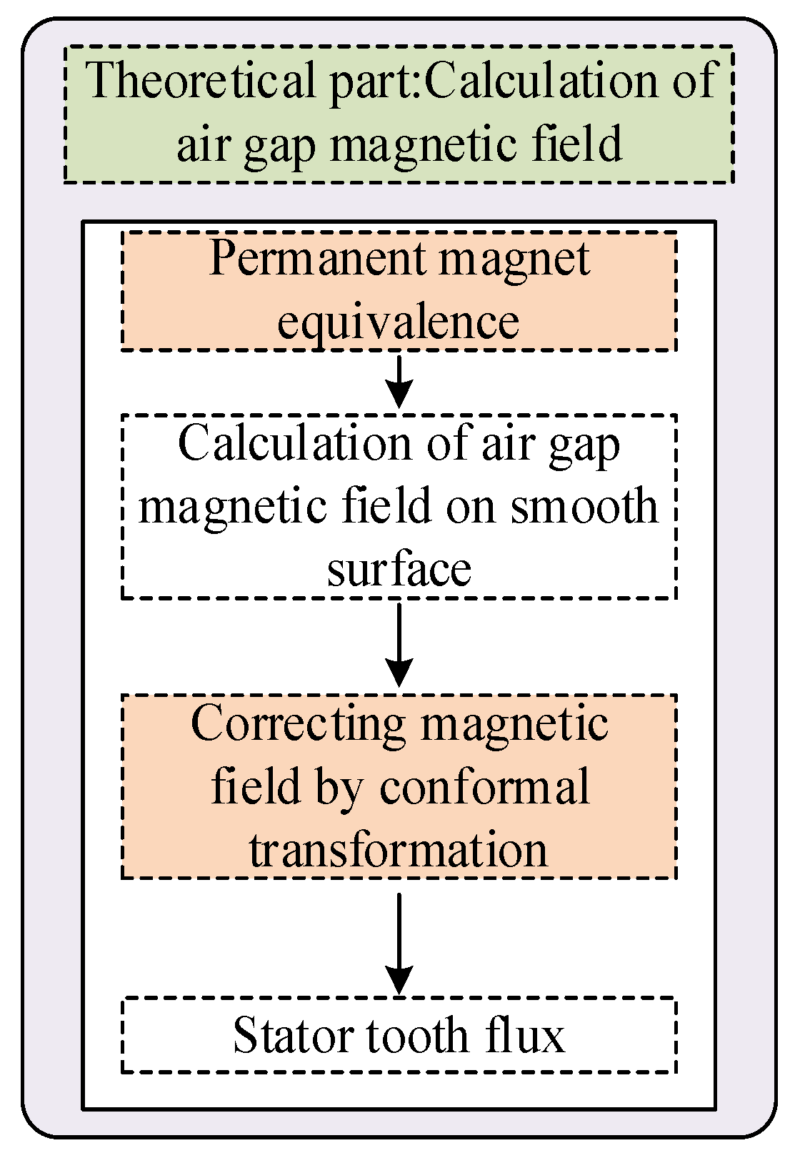
2. Materials and Methods
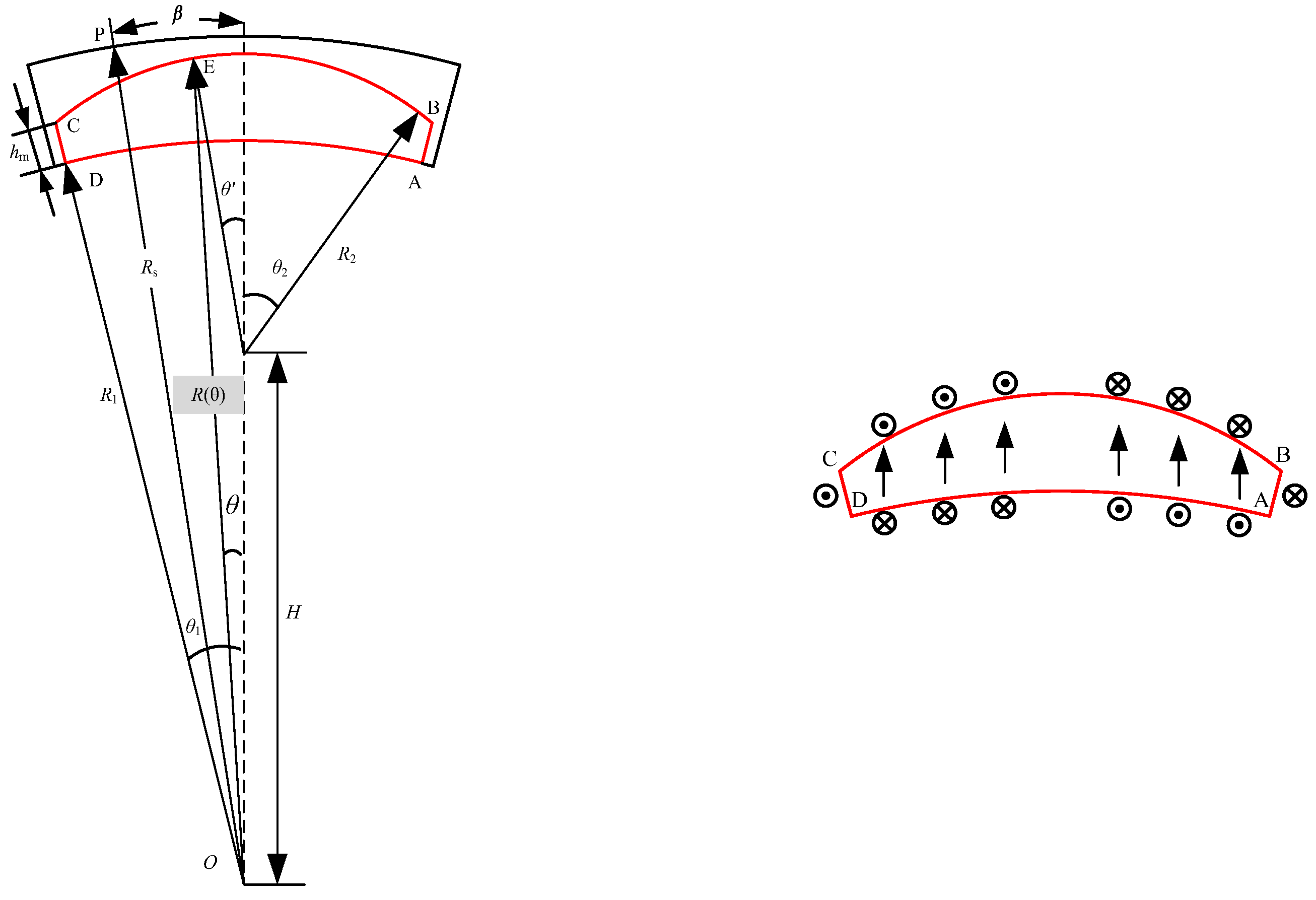
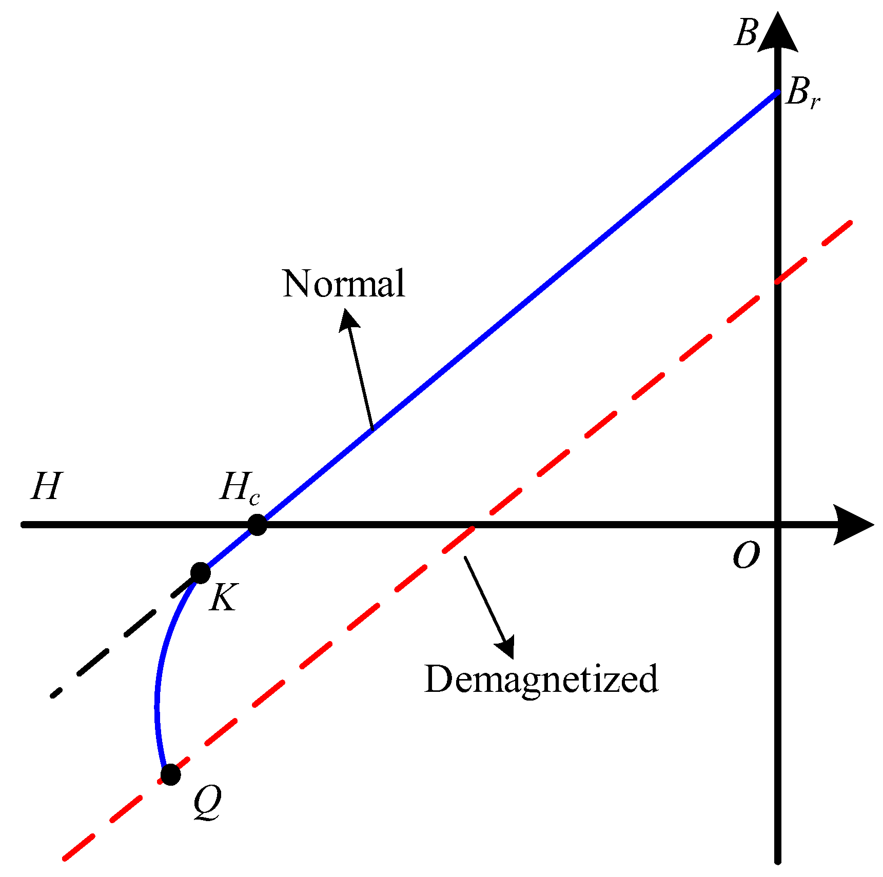
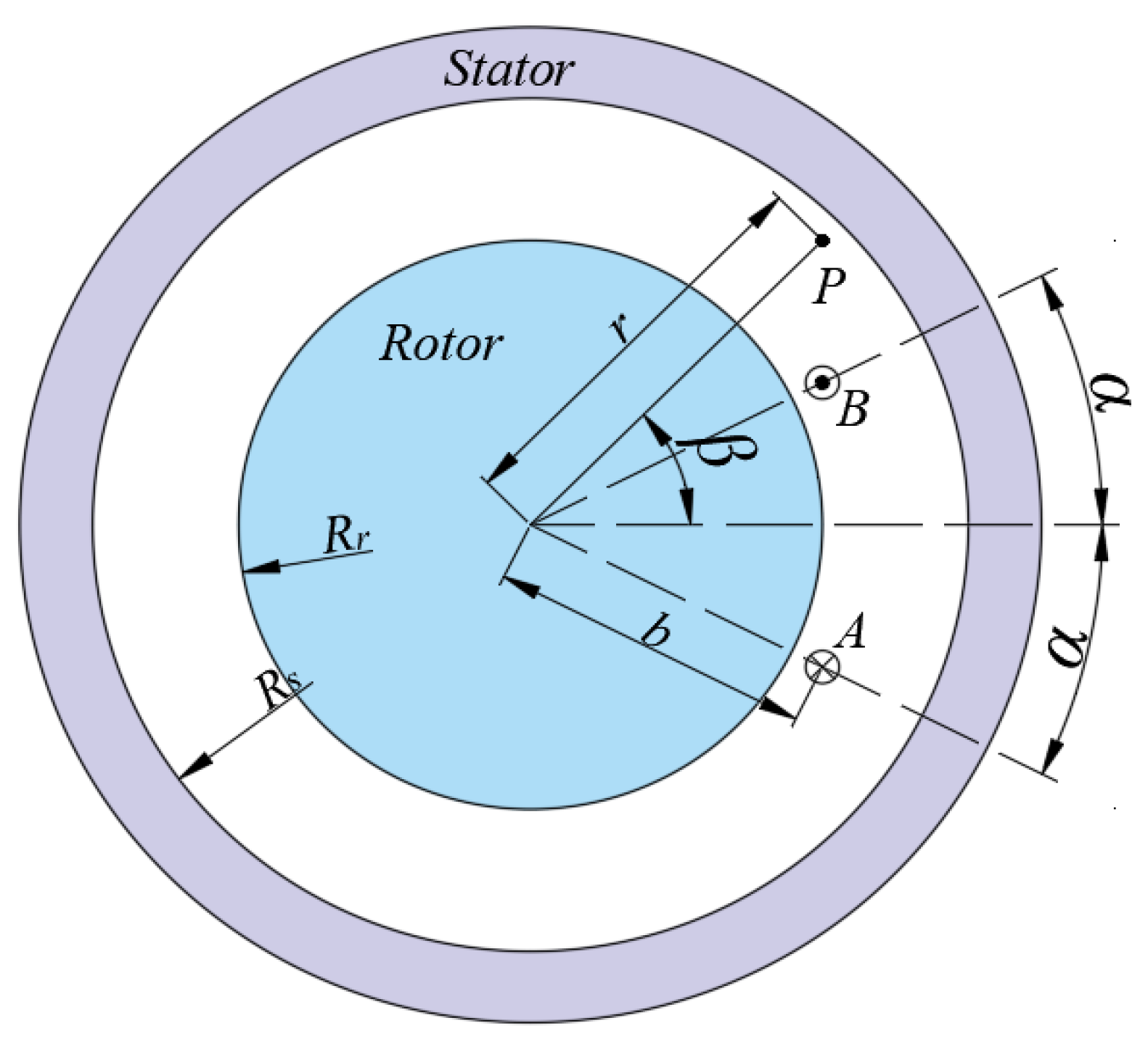
2.1. Magnetic Pole Surface Current Equivalence
2.2. Calculation of Air-Gap Magnetic Field of a Current-Carrying Coil
2.3. Calculation of Complex Relative Permeance of Air Gap
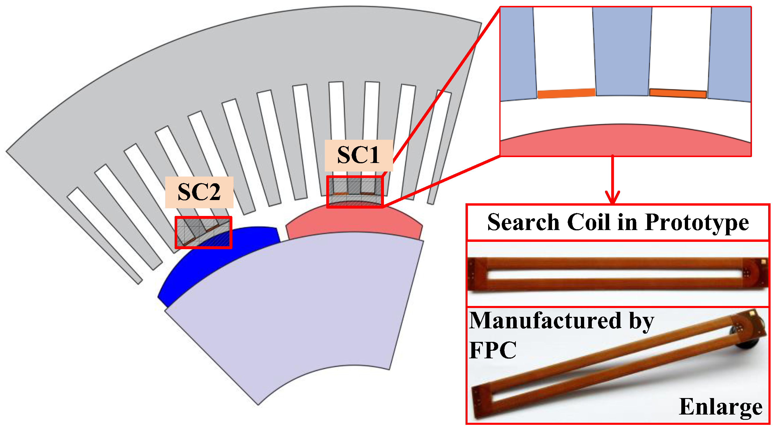
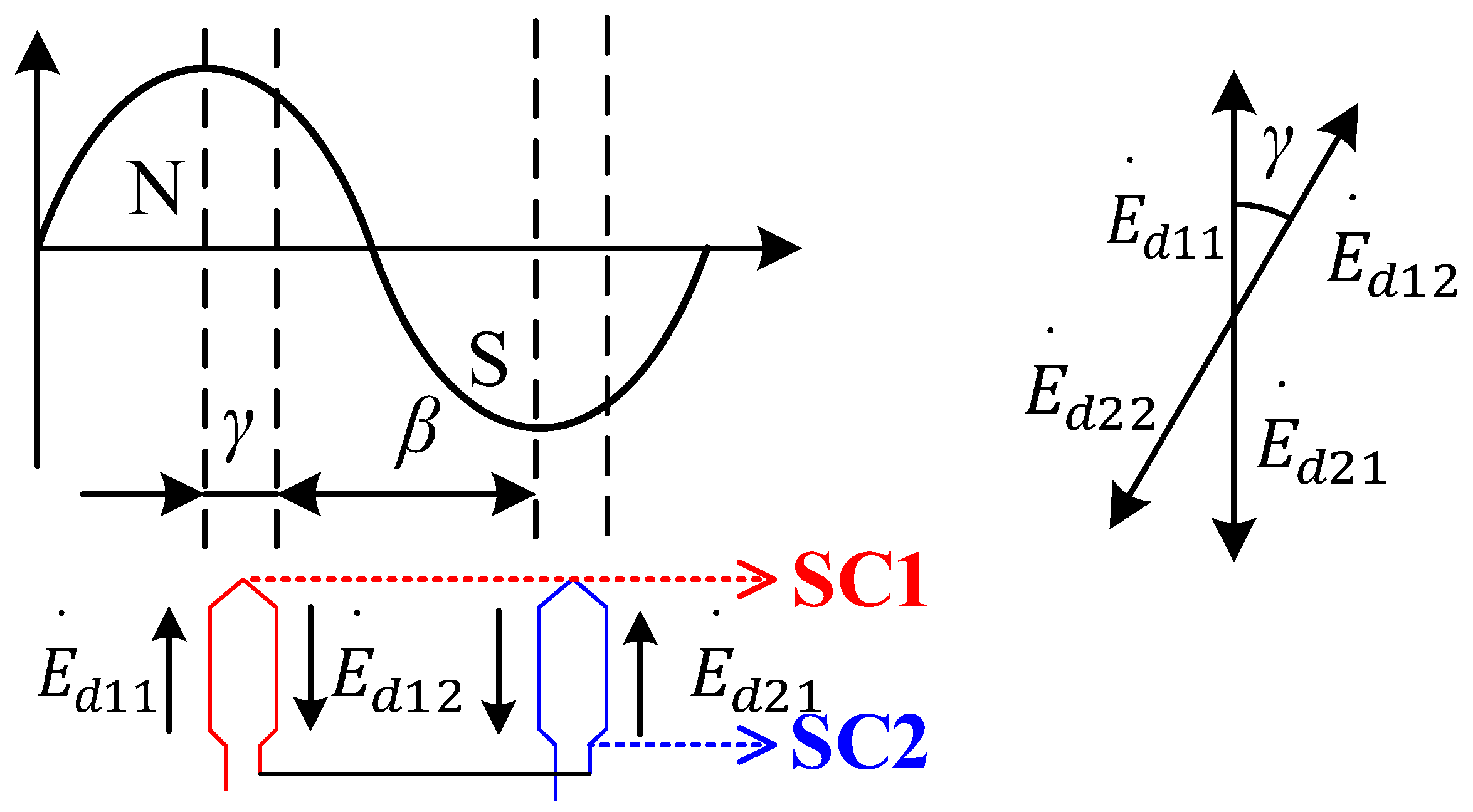
2.4. Search Coil Arrangement Scheme
3. Results
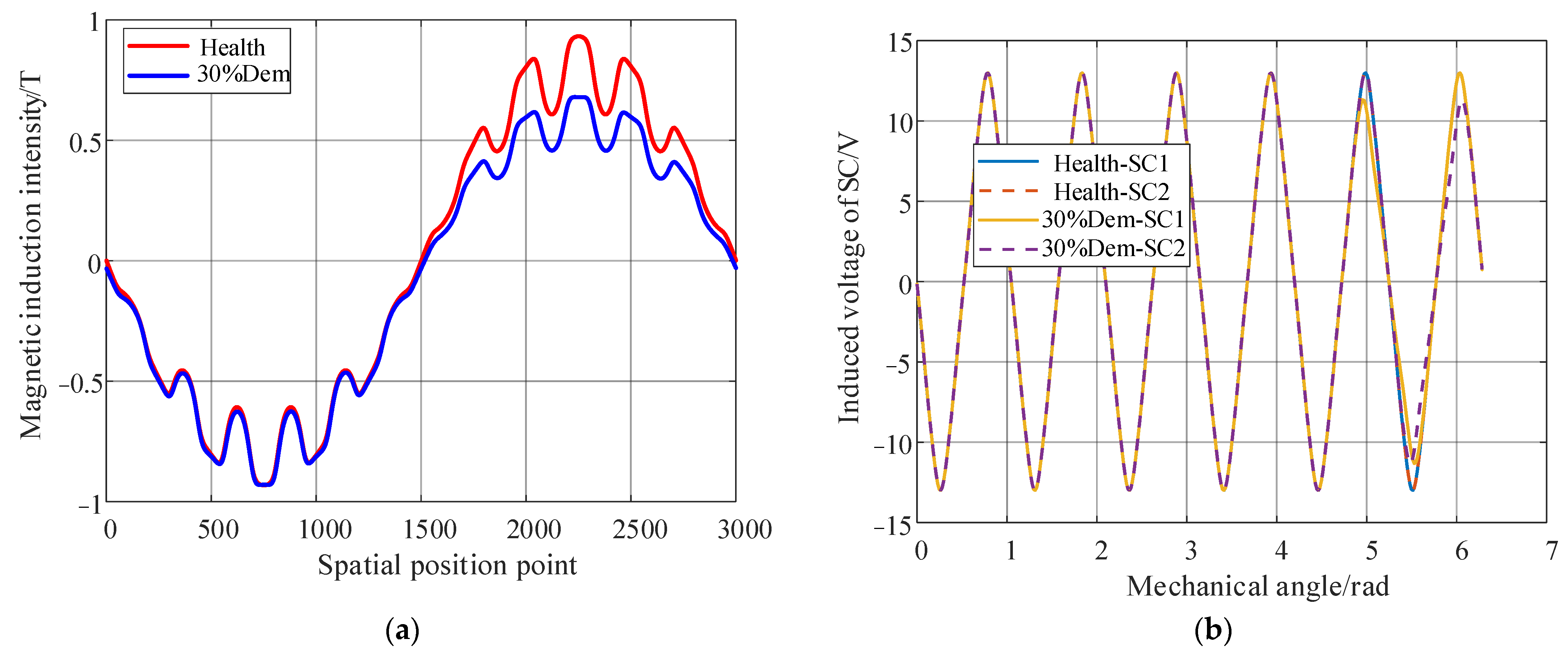
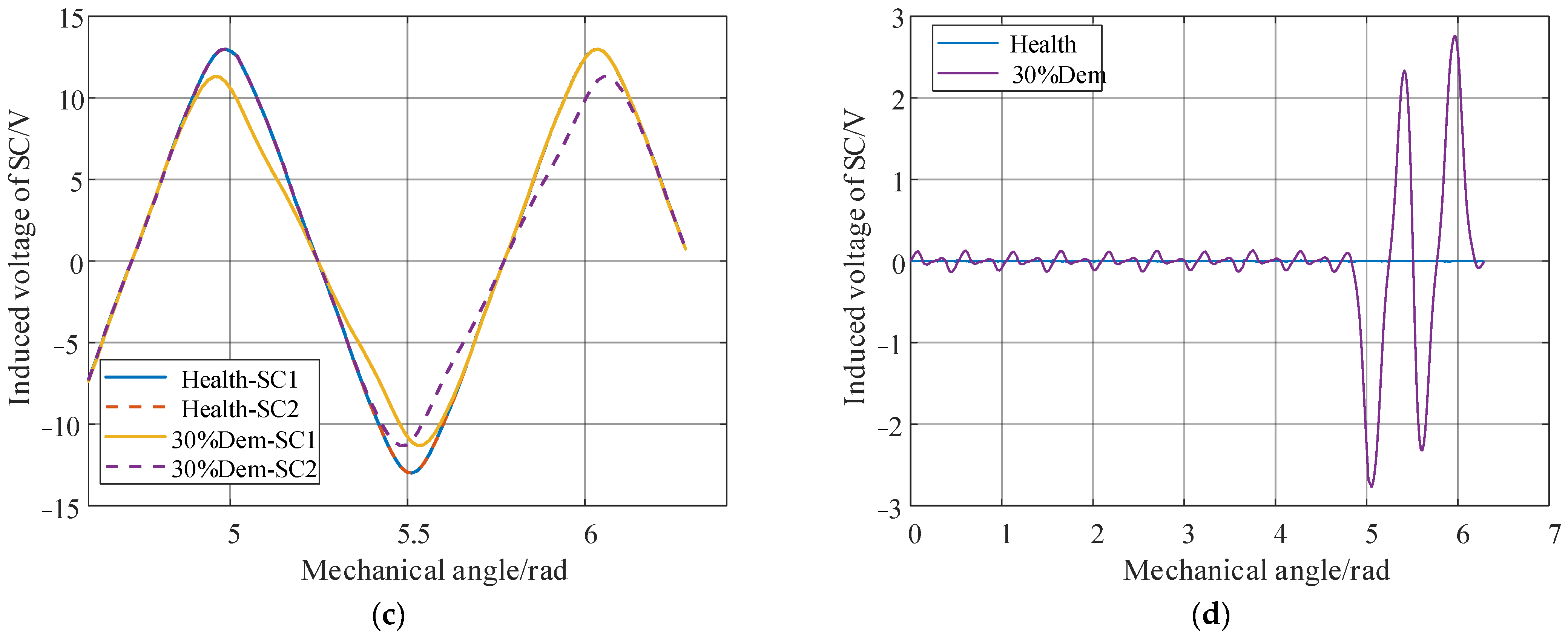
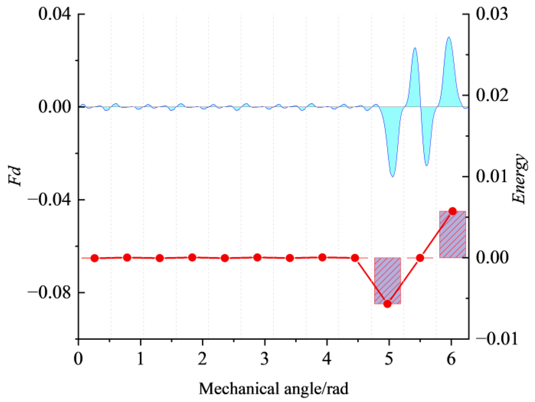
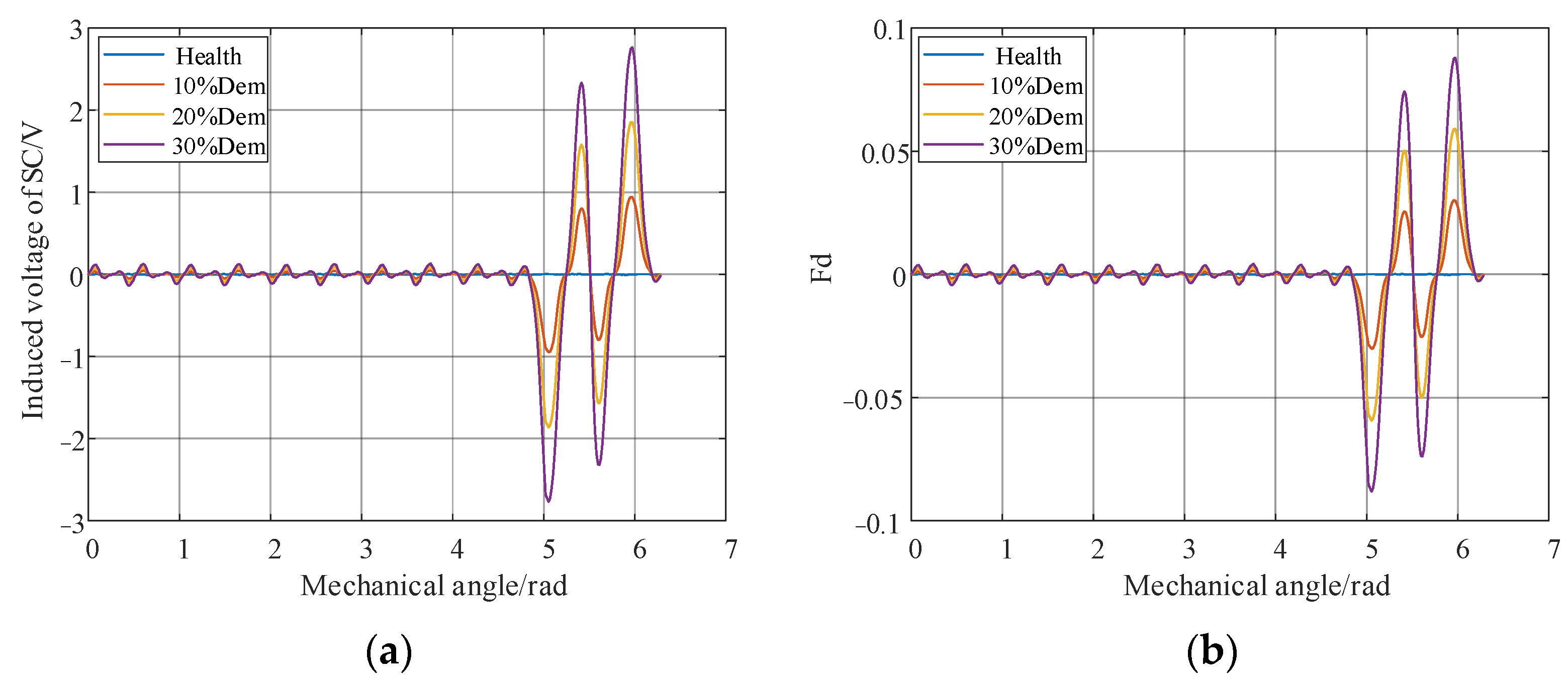
3.1. Simulation Results
- (a)
- Changing the remanence of the permanent magnet
- (b)
- Appling demagnetizing excitation
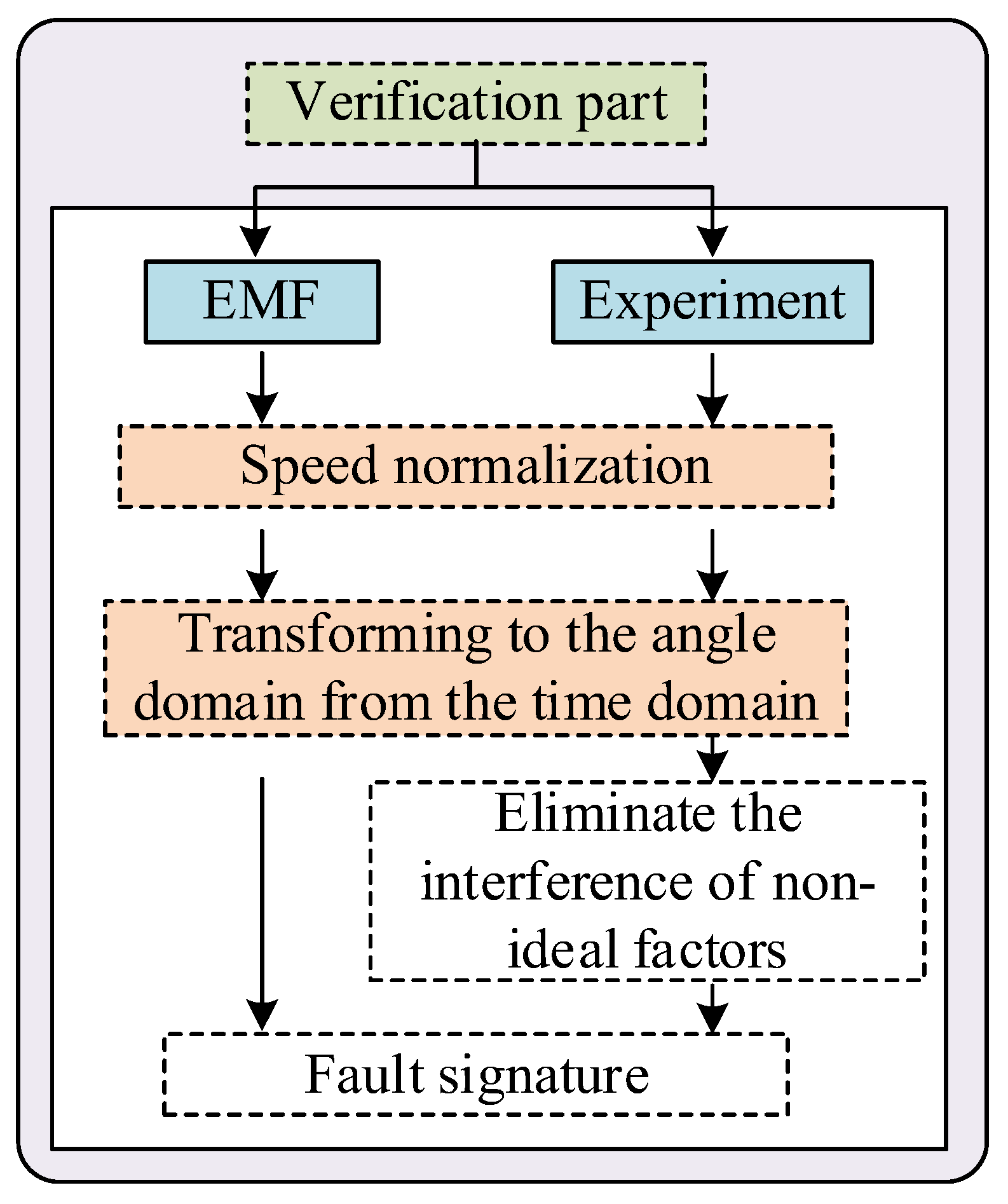
3.2. Experimental Platform
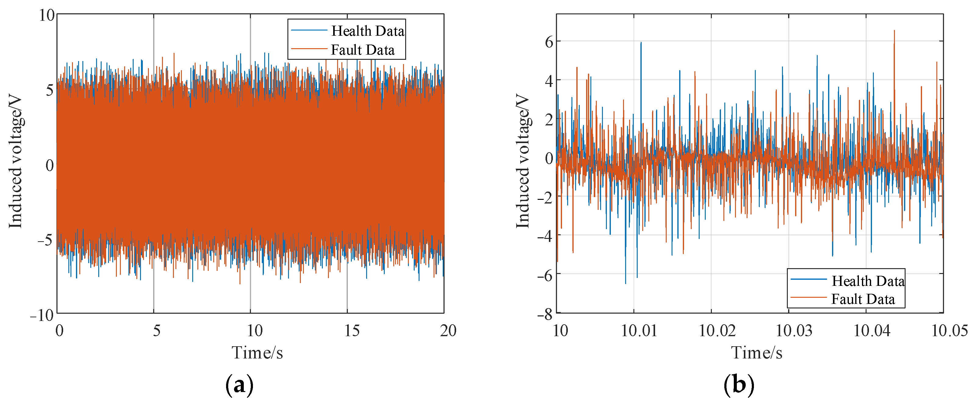
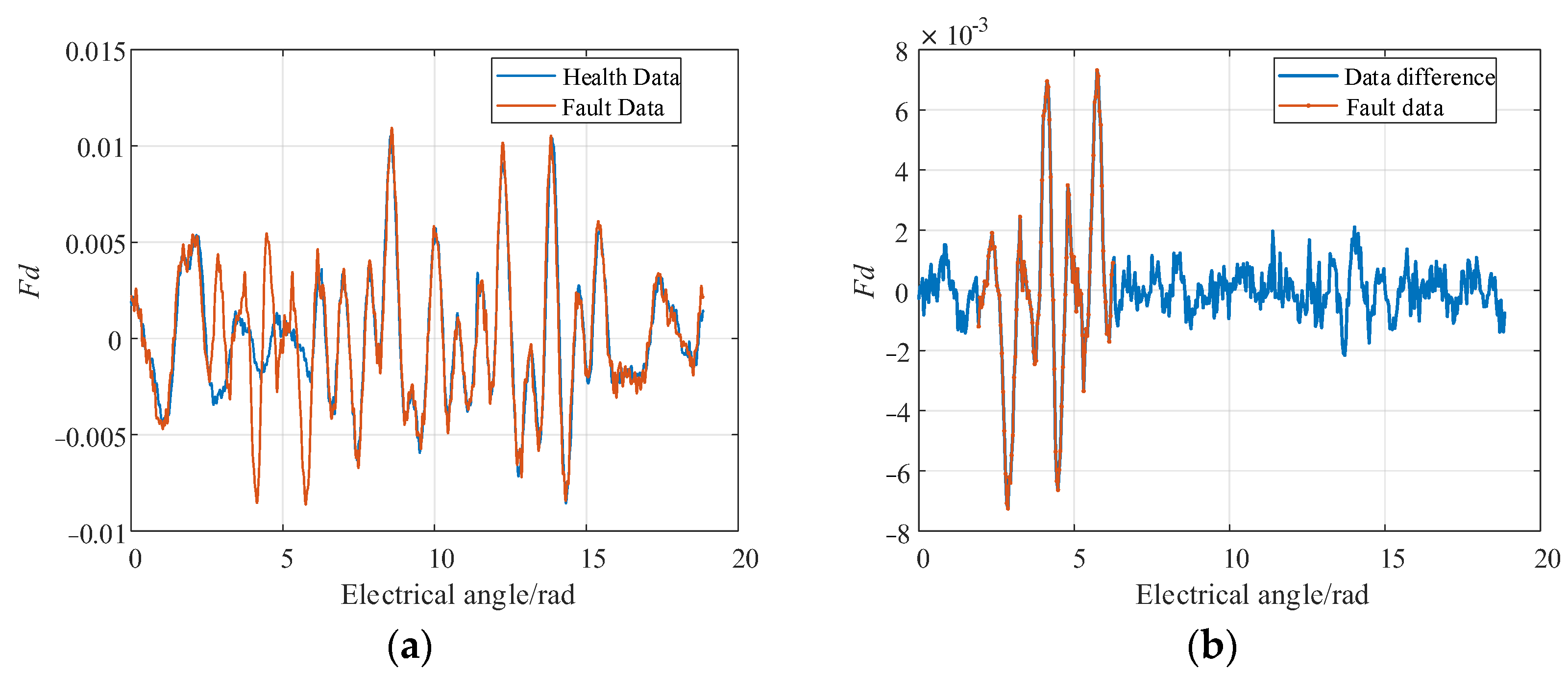
3.3. Experimental Results
- (a)
- Changing the demagnetizing current
- (b)
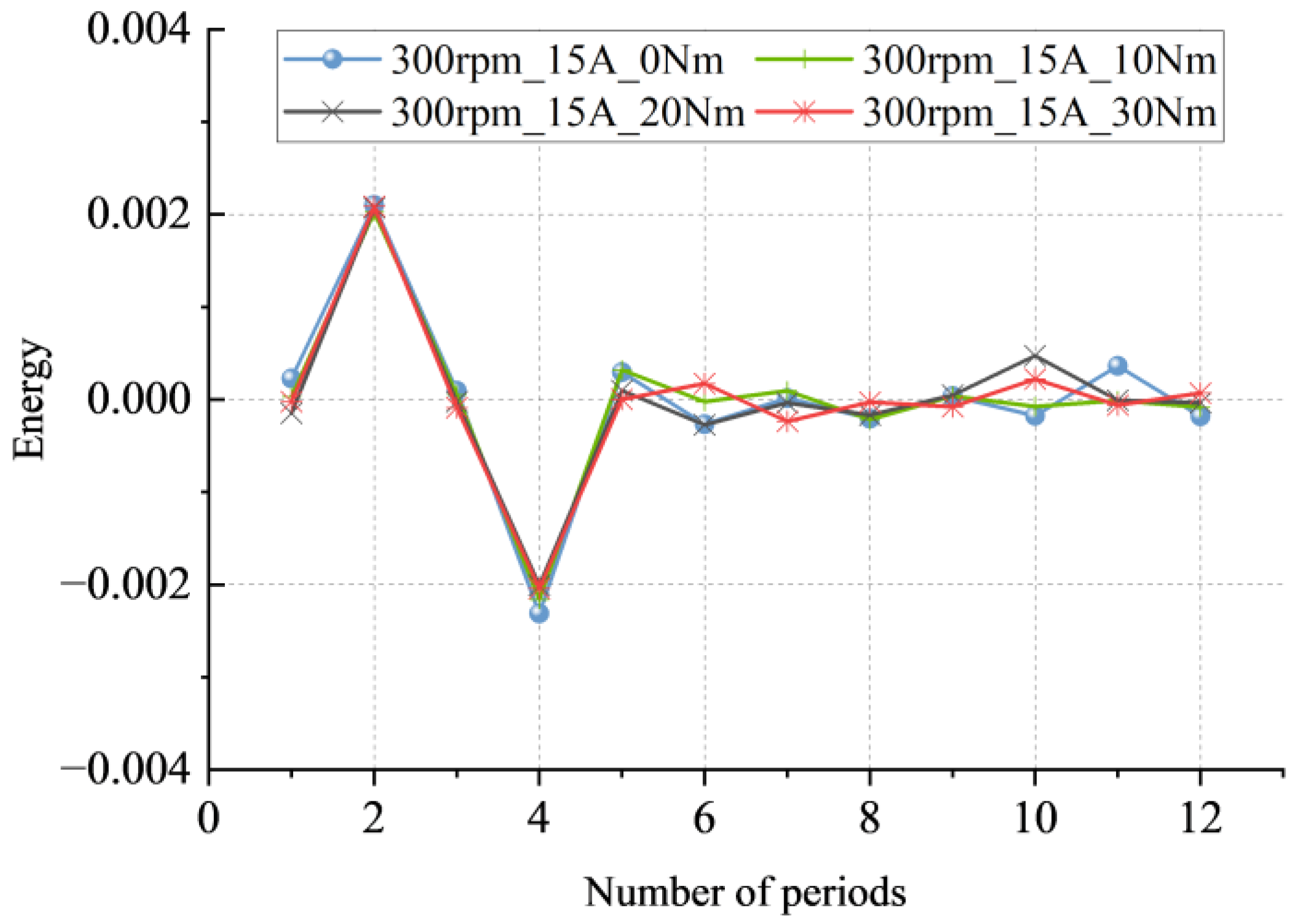
- Change in load
- (c)
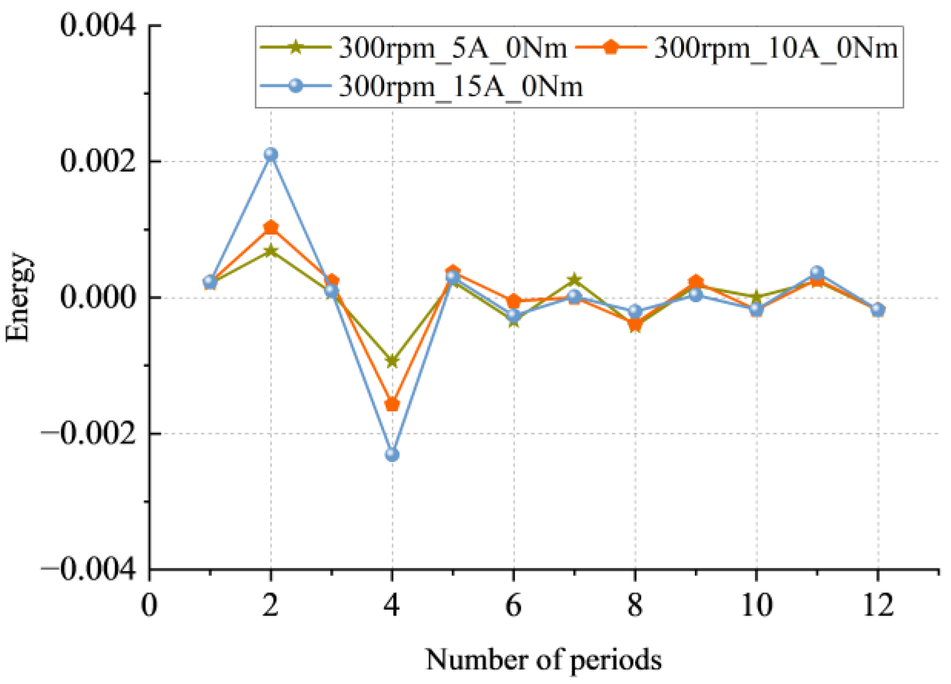
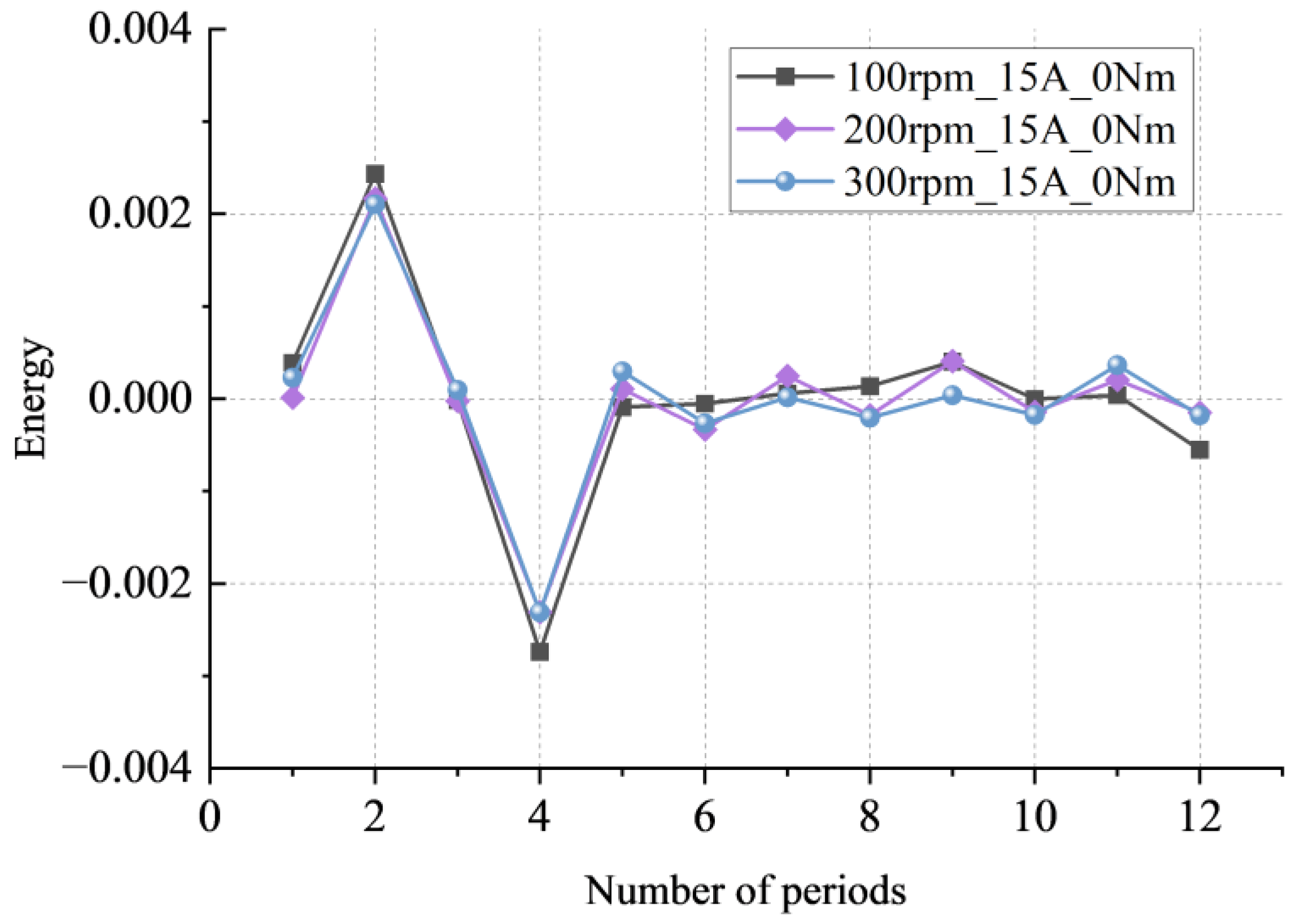
- Change in speed
4. Discussion
5. Conclusions
Author Contributions
Funding
Data Availability Statement
Acknowledgments
Conflicts of Interest
Appendix A

| Parameter | Value | Parameter | Value |
|---|---|---|---|
| Length of the unilateral air gap | 2 mm | Slot width | 4.2 mm |
| Stator outer diameter | 290 mm | Thickness of permanent magnet | 9 mm |
| Inner diameter of the stator | 180 mm | Overlaying coefficient | 0.97 |
| Rotor outer diameter | 176 mm | Number of stator slots | 72 |
| Inside diameter of the rotor | 80 mm | Number of conductors per slot | 72 |
| Stator core length | 88 mm | Number of parallel branches | 1 |
| Yoke thickness | 22 mm | Pitch | 6 |
| Stator core material | 50WW310 | Winding coefficient | 1 |
| Rotor core material | 16 Mn | Permanent magnet material | SmCo30 |
Appendix B

Appendix C
References
- Zdorovets, M.V.; Kozlovskiy, A.L.; Shlimas, D.I.; Borgekov, D.B. Phase transformations in FeCo—Fe2CoO4/Co3O4-spinel nanostructures as a result of thermal annealing and their practical application. J. Mater. Sci. Mater. Electron. 2021, 32, 16694–16705. [Google Scholar] [CrossRef]
- Turchenko, V.A.; Trukhanov, S.V.; Balagurov, A.M.; Kostishyn, V.G.; Trukhanov, A.V.; Panina, L.V.; Trukhanova, E.L. Features of crystal structure and dual ferroic properties of BaFe12-xMexO19 (Me = In3+ and Ga3+; x = 0.1–1.2). J. Magn. Magn. Mater. 2018, 464, 139–147. [Google Scholar] [CrossRef]
- Huang, F.; Zhang, X.; Qin, G.; Xie, J.; Peng, J.; Huang, S.; Long, Z.; Tang, Y. Demagnetization Fault Diagnosis of Permanent Magnet Synchronous Motors Using Magnetic Leakage Signals. IEEE Trans. Ind. Inform. 2023, 19, 6105–6116. [Google Scholar] [CrossRef]
- Rafaq, M.S.; Lee, H.J.; Park, Y.; Lee, S.B.; Zapico, M.O.; Fernandez, D.; Reigosa, D.; Briz, F. Airgap Search Coil Based Identification of PM Synchronous Motor Defects. IEEE Trans. Ind. Electron. 2022, 69, 6551–6560. [Google Scholar] [CrossRef]
- Faiz, J.; Mazaheri-Tehrani, E. Demagnetization Modeling and Fault Diagnosing Techniques in Permanent Magnet Machines Under Stationary and Nonstationary Conditions: An Overview. IEEE Trans. Ind. Appl. 2017, 53, 2772–2785. [Google Scholar] [CrossRef]
- Zhivulin, V.E.; Trofimov, E.A.; Zaitseva, O.V.; Sherstyuk, D.P.; Cherkasova, N.A.; Taskaev, S.V.; Vinnik, D.A.; Alekhina, Y.A.; Perov, N.S.; Naidu, K.C.B.; et al. Preparation, phase stability, and magnetization behavior of high entropy hexaferrites. iScience 2023, 26, 107077. [Google Scholar] [CrossRef]
- Tuleushev, A.Z.; Harrison, F.E.; Kozlovskiy, A.L.; Zdorovets, M.V. Evolution of the absorption edge of PET films irradiated with Kr ions after thermal annealing and ageing. Opt. Mater. 2021, 119, 111348. [Google Scholar] [CrossRef]
- Kozlovskiy, A.L.; Shlimas, D.I.; Zdorovets, M.V. Synthesis, structural properties and shielding efficiency of glasses based on TeO2-(1-x)ZnO-xSm2O3. J. Mater. Sci. Mater. Electron. 2021, 32, 12111–12120. [Google Scholar] [CrossRef]
- Almessiere, M.A.; Algarou, N.A.; Slimani, Y.; Sadaqat, A.; Baykal, A.; Manikandan, A.; Trukhanov, S.V.; Trukhanov, A.V.; Ercan, I. Investigation of exchange coupling and microwave properties of hard/soft (SrNi0.02Zr0.01Fe11.96O19)/(CoFe2O4)x nanocomposites. Mater. Today Nano 2022, 18, 100186. [Google Scholar] [CrossRef]
- Torregrossa, D.; Khoobroo, A.; Fahimi, B. Prediction of Acoustic Noise and Torque Pulsation in PM Synchronous Machines With Static Eccentricity and Partial Demagnetization Using Field Reconstruction Method. IEEE Trans. Ind. Electron. 2012, 59, 934–944. [Google Scholar] [CrossRef]
- Moon, S.; Lee, J.; Jeong, H.; Kim, S.W. Demagnetization Fault Diagnosis of a PMSM Based on Structure Analysis of Motor Inductance. IEEE Trans. Ind. Electron. 2016, 63, 3795–3803. [Google Scholar] [CrossRef]
- Skowron, M.; Orlowska-Kowalska, T.; Kowalski, C.T. Detection of Permanent Magnet Damage of PMSM Drive Based on Direct Analysis of the Stator Phase Currents Using Convolutional Neural Network. IEEE Trans. Ind. Electron. 2022, 69, 13665–13675. [Google Scholar] [CrossRef]
- Moon, S.; Jeong, H.; Lee, H.; Kim, S.W. Detection and Classification of Demagnetization and Interturn Short Faults of IPMSMs. IEEE Trans. Ind. Electron. 2017, 64, 9433–9441. [Google Scholar] [CrossRef]
- Espinosa, A.G.; Rosero, J.A.; Cusidó, J.; Romeral, L.; Ortega, J.A. Fault Detection by Means of Hilbert–Huang Transform of the Stator Current in a PMSM With Demagnetization. IEEE Trans. Energy Convers. 2010, 25, 312–318. [Google Scholar] [CrossRef]
- Hong, J.; Hyun, D.; Lee, S.B.; Yoo, J.Y.; Lee, K.W. Automated Monitoring of Magnet Quality for Permanent-Magnet Synchronous Motors at Standstill. IEEE Trans. Ind. Appl. 2010, 46, 1397–1405. [Google Scholar] [CrossRef]
- Brela, M.; Michalski, M.; Gebhardt, H.J.; Franke, J. Hall measurement method for the detection of material defects in plastic-embedded permanent magnets of rotors. In Proceedings of the IECON 2013—39th Annual Conference of the IEEE Industrial Electronics Society, Vienna, Austria, 10–13 November 2013; pp. 3928–3934. [Google Scholar]
- Roux, W.l.; Harley, R.G.; Habetler, T.G. Detecting Rotor Faults in Low Power Permanent Magnet Synchronous Machines. IEEE Trans. Power Electron. 2007, 22, 322–328. [Google Scholar] [CrossRef]
- Chakraborty, S.; Keller, E.; Ray, A.; Mayer, J. Detection and estimation of demagnetization faults in permanent magnet synchronous motors. Electr. Power Syst. Res. 2013, 96, 225–236. [Google Scholar] [CrossRef]
- Rajagopalan, S.; Roux, W.l.; Habetler, T.G.; Harley, R.G. Dynamic Eccentricity and Demagnetized Rotor Magnet Detection in Trapezoidal Flux (Brushless DC) Motors Operating Under Different Load Conditions. IEEE Trans. Power Electron. 2007, 22, 2061–2069. [Google Scholar] [CrossRef]
- Khoobroo, A.; Fahimi, B. A novel method for permanent magnet demagnetization fault detection and treatment in permanent magnet synchronous machines. In Proceedings of the 2010 Twenty-Fifth Annual IEEE Applied Power Electronics Conference and Exposition (APEC), Palm Springs, CA, USA, 21–25 February 2010; pp. 2231–2237. [Google Scholar]
- Kliman, G.B.; Stein, J. Methods of Motor Current Signature Analysis. Electr. Mach. Power Syst. 1992, 20, 463–474. [Google Scholar] [CrossRef]
- Thomson, W.T.; Fenger, M. Current signature analysis to detect induction motor faults. IEEE Ind. Appl. Mag. 2001, 7, 26–34. [Google Scholar] [CrossRef]
- Zafarani, M.; Goktas, T.; Akin, B. A comprehensive analysis of magnet defect faults in permanent magnet synchronous motors. In Proceedings of the 2015 IEEE Applied Power Electronics Conference and Exposition (APEC), Long Beach, CA, USA, 15–19 March 2015; pp. 2779–2783. [Google Scholar]
- Goktas, T.; Zafarani, M.; Akin, B. Discernment of Broken Magnet and Static Eccentricity Faults in Permanent Magnet Synchronous Motors. IEEE Trans. Energy Convers. 2016, 31, 578–587. [Google Scholar] [CrossRef]
- Rajagopalan, S.; Aller, J.M.; Restrepo, J.A.; Habetler, T.G.; Harley, R.G. Detection of Rotor Faults in Brushless DC Motors Operating Under Nonstationary Conditions. IEEE Trans. Ind. Appl. 2006, 42, 1464–1477. [Google Scholar]
- Rajagopalan, S.; Aller, J.M.; Restrepo, J.A.; Habetler, T.G.; Harley, R.G. Analytic-Wavelet-Ridge-Based Detection of Dynamic Eccentricity in Brushless Direct Current (BLDC) Motors Functioning Under Dynamic Operating Conditions. IEEE Trans. Ind. Electron. 2007, 54, 1410–1419. [Google Scholar] [CrossRef]
- Ruiz, J.R.; Rosero, J.A.; Espinosa, A.G.; Romeral, L. Detection of Demagnetization Faults in Permanent-Magnet Synchronous Motors Under Nonstationary Conditions. IEEE Trans. Magn. 2009, 45, 2961–2969. [Google Scholar] [CrossRef]
- Ruiz, J.R.R.; Espinosa, A.G.; Romeral, L.; Cusidó, J. Demagnetization diagnosis in permanent magnet synchronous motors under non-stationary speed conditions. Electr. Power Syst. Res. 2010, 80, 1277–1285. [Google Scholar] [CrossRef]
- Urresty, J.; Riba, J.; Delgado, M.; Romeral, L. Detection of Demagnetization Faults in Surface-Mounted Permanent Magnet Synchronous Motors by Means of the Zero-Sequence Voltage Component. IEEE Trans. Energy Convers. 2012, 27, 42–51. [Google Scholar] [CrossRef]
- Ebrahimi, B.M.; Faiz, J. Demagnetization Fault Diagnosis in Surface Mounted Permanent Magnet Synchronous Motors. IEEE Trans. Magn. 2013, 49, 1185–1192. [Google Scholar] [CrossRef]
- Urresty, J.; Atashkhooei, R.; Riba, J.; Romeral, L.; Royo, S. Shaft Trajectory Analysis in a Partially Demagnetized Permanent-Magnet Synchronous Motor. IEEE Trans. Ind. Electron. 2013, 60, 3454–3461. [Google Scholar] [CrossRef]
- Yang, Z.; Shi, X.; Krishnamurthy, M. Vibration monitoring of PM synchronous machine with partial demagnetization and inter-turn short circuit faults. In Proceedings of the 2014 IEEE Transportation Electrification Conference and Expo (ITEC), Dearborn, MI, USA, 15–18 June 2014; pp. 1–6. [Google Scholar]
- Rezig, A.; Mekideche, M.R.; Djerdir, A. Impact of Eccentricity and Demagnetization Faults on Magnetic Noise Generation in Brushless Permanent Magnet DC Motors. J. Electr. Eng. Technol. 2011, 6, 356–363. [Google Scholar] [CrossRef]
- Hong, J.; Park, S.; Hyun, D.; Kang, T.; Lee, S.B.; Kral, C.; Haumer, A. Detection and Classification of Rotor Demagnetization and Eccentricity Faults for PM Synchronous Motors. IEEE Trans. Ind. Appl. 2012, 48, 923–932. [Google Scholar] [CrossRef]
- Eker, M.; Gündogan, B. Demagnetization fault detection of permanent magnet synchronous motor with convolutional neural network. Electr. Eng. 2023, 105, 1695–1708. [Google Scholar] [CrossRef]
- Zeng, C.; Huang, S.; Lei, J.; Wan, Z.; Yang, Y. Online Rotor Fault Diagnosis of Permanent Magnet Synchronous Motors Based on Stator Tooth Flux. IEEE Trans. Ind. Appl. 2021, 57, 2366–2377. [Google Scholar] [CrossRef]
- Da, Y.; Shi, X.; Krishnamurthy, M. A New Approach to Fault Diagnostics for Permanent Magnet Synchronous Machines Using Electromagnetic Signature Analysis. IEEE Trans. Power Electron. 2013, 28, 4104–4112. [Google Scholar] [CrossRef]
- Driscoll, T.A.; Trefethen, L.N. Schwarz-Christoffel Mapping; Cambridge University Press: Cambridge, UK, 2002. [Google Scholar]
- Park, Y.; Fernandez, D.; Lee, S.B.; Hyun, D.; Jeong, M.; Kommuri, S.K.; Cho, C.; Reigosa, D.D.; Briz, F. Online Detection of Rotor Eccentricity and Demagnetization Faults in PMSMs Based on Hall-Effect Field Sensor Measurements. IEEE Trans. Ind. Appl. 2019, 55, 2499–2509. [Google Scholar] [CrossRef]
- Fernandez, D.; Hyun, D.; Park, Y.; Reigosa, D.D.; Lee, S.B.; Lee, D.M.; Briz, F. Permanent Magnet Temperature Estimation in PM Synchronous Motors Using Low-Cost Hall Effect Sensors. IEEE Trans. Ind. Appl. 2017, 53, 4515–4525. [Google Scholar] [CrossRef]
- Reigosa, D.; Fernández, D.; Martínez, M.; Park, Y.; Lee, S.B.; Briz, F. Permanent Magnet Synchronous Machine Non-Uniform Demagnetization Detection Using Zero-Sequence Magnetic Field Density. IEEE Trans. Ind. Appl. 2019, 55, 3823–3833. [Google Scholar] [CrossRef]
- Jeong, J.; Lee, H.; Orviz, M.; Lee, S.B.; Reigosa, D.; Briz, F. Detection of Trailing Edge PM Demagnetization in Surface PM Synchronous Motors. IEEE Trans. Ind. Appl. 2023, 59, 3390–3399. [Google Scholar] [CrossRef]
- Ahsanullah, K.; Jeyasankar, E.; Panda, S.K.; Shanmukha, R.; Nadarajan, S. Detection and analysis of winding and demagnetization faults in PMSM based marine propulsion motors. In Proceedings of the 2017 IEEE International Electric Machines and Drives Conference (IEMDC), Miami, FL, USA, 21–24 May 2017; pp. 1–7. [Google Scholar]


| Parameter | Value | Parameter | Value |
|---|---|---|---|
| Rated Power (kW) | 0.94 | Rated Speed (r/min) | 300 |
| Rated Torque (Nm) | 30 | Stator Resistance (Ω) | 4.3 |
| Number of Pole Pairs | 6 | PM Flux Linkage (wb) | 0.98 |
Disclaimer/Publisher’s Note: The statements, opinions and data contained in all publications are solely those of the individual author(s) and contributor(s) and not of MDPI and/or the editor(s). MDPI and/or the editor(s) disclaim responsibility for any injury to people or property resulting from any ideas, methods, instructions or products referred to in the content. |
© 2023 by the authors. Licensee MDPI, Basel, Switzerland. This article is an open access article distributed under the terms and conditions of the Creative Commons Attribution (CC BY) license (https://creativecommons.org/licenses/by/4.0/).
Share and Cite
Huang, W.; Chen, J.; Su, W.; Liu, H.; Lv, K.; Hu, J. A Period Energy Method for Demagnetization Detection in Surface Permanent Magnet Motors with Search Coils. Electronics 2023, 12, 3514. https://doi.org/10.3390/electronics12163514
Huang W, Chen J, Su W, Liu H, Lv K, Hu J. A Period Energy Method for Demagnetization Detection in Surface Permanent Magnet Motors with Search Coils. Electronics. 2023; 12(16):3514. https://doi.org/10.3390/electronics12163514
Chicago/Turabian StyleHuang, Wen, Junquan Chen, Wu Su, Haitao Liu, Ke Lv, and Jinghua Hu. 2023. "A Period Energy Method for Demagnetization Detection in Surface Permanent Magnet Motors with Search Coils" Electronics 12, no. 16: 3514. https://doi.org/10.3390/electronics12163514
APA StyleHuang, W., Chen, J., Su, W., Liu, H., Lv, K., & Hu, J. (2023). A Period Energy Method for Demagnetization Detection in Surface Permanent Magnet Motors with Search Coils. Electronics, 12(16), 3514. https://doi.org/10.3390/electronics12163514