Abstract
In the application of 3D reconstruction of multi-cameras, it is necessary to calibrate the camera used separately, and at the same time carry out multi-stereo calibration, and the calibration accuracy directly affects the effect of the 3D reconstruction of the system. Many researchers focus on the optimization of the calibration algorithm and the improvement of calibration accuracy after obtaining the calibration plate pattern coordinates, ignoring the impact of calibration on the accuracy of the calibration board pattern coordinate extraction. Therefore, this paper proposes a multi-camera stereo calibration method based on circular calibration plate focusing on the extraction of pattern features during the calibration process. This method preforms the acquisition of the subpixel edge acquisition based on Franklin matrix and circular feature extraction of the circular calibration plate pattern collected by the camera, and then combines the Zhang’s calibration method to calibrate the camera. Experimental results show that compared with the traditional calibration method, the method has better calibration effect and calibration accuracy, and the average reprojection error of the multi-camera is reduced by more than 0.006 pixels.
1. Introduction
Multi-camera calibration is a key step to achieve multi-vision detection and multi-view stereo vision. The following purposes can be achieved through multi-camera calibration, the first is to determine the conversion relationship between the three-dimensional points in the real scene and the pixels in the image, the second is to determine the distortion factor in the camera imaging process for image correction, and the third is to reduce the requirements on the acquisition equipment through calibration technology. Theoretically, the optical axis of multiple cameras needs to be kept parallel or maintain the same tilt angle, which is difficult to achieve in practice. Stereo calibration can calculate the relative posture between multiple cameras, thereby reducing the equipment requirements, which is conducive to the application of multi-eye vision inspection technology in real production.
Camera calibration is to solve the basic parameters of camera imaging and the orientation of the world coordinate system by using the mapping relationship between the three-dimensional object position of the known feature point and the two-dimensional image coordinate according to the geometric model of camera imaging [1]. According to the different solution methods of calibration parameters and reference objects, camera calibration technology is mainly divided into three types: traditional calibration method, self-calibration method and active visual calibration method [2]. The most representative is the Zhang’s calibration method with chessboard as the calibration image in the traditional calibration method [3]. The method uses an international chess pattern calibration board as the calibration object, and uses the camera to shoot the calibration object in different directions and different postures for many times. The one-to-one correspondence between the image points and the three-dimensional space points is established to calibrate the camera by extracting the corner points in the calibration object. This method is simple and efficient, is often used in the calibration process. The latest monocular camera calibration algorithm based on improved particle swarm algorithm proposed by Tian et al. effectively overcomes the problem of falling into local optimal solution [4].
In the process of using checkerboard calibration, the accuracy of corner point extraction is greatly affected by noise and image quality, while circular features have strong inhibition of noise and high recognition rate, so circular features play an important role in the visual system. Heikkila et al. [5] firstly proposed the use of a circular pattern as a calibration target, and repeatedly corrected the perspective effect by obtaining the centroid of the circular pattern, realizing the real-time calibration of the camera of the precision 3D vision system. Shan et al. [6] used the Cannny-Zernike combined algorithm to achieve subpixel positioning of the center coordinates of the circle calibration template, and proposed a circle center sorting method based on triangle markers, using the distance between the two solid circles on the diagonal of the solid circle target as a constraint condition, and optimizing the external parameters of the camera with Levenberg–Marquardt (LM), which had good calibration accuracy and degree of automation. In the latest, Chen et al. [7] used computer-simulated random speckles as calibration targets, combined with advanced digital image correlation (DIC) algorithms to accurately match the control points of the calibration targets with the corresponding points on the captured calibration images, and realized the accurate extraction of parameters inside and outside the camera.
In view of the influence of the accuracy of the feature extraction of the calibration pattern on the calibration results in the calibration process, this paper uses the circle as the basic pattern of the calibration plate. Firstly, the collected images are preprocessed such as greyscale. At the same time, the single circle in the circular calibration plate image is segmented for subpixel edge detection, and the subpixel circular edge with higher accuracy is obtained [8], and then the characteristic circle center is obtained by using the image moment method, and finally the camera calibration is combined with Zhang Zhengyou calibration method, and the experimental results show that the proposed method has a better calibration effect and accuracy.
This article is organized as follows: Section 2 introduces the imaging model and calibration method of the camera; Section 3 details the image acquisition platform used, explaining the proposed camera calibration method and experimental steps; Section 4 conducts experiments and analyzes the experimental data and obtains experimental results; and finally, in Section 5, the full text is summarized.
2. Related Works
2.1. Camera Model
In the process of stereoscopic perception, a series of coordinate systems must be constructed as references, usually divided into world coordinate systems, camera coordinate systems, image coordinate systems, and pixel coordinate systems [9], as shown in Figure 1.
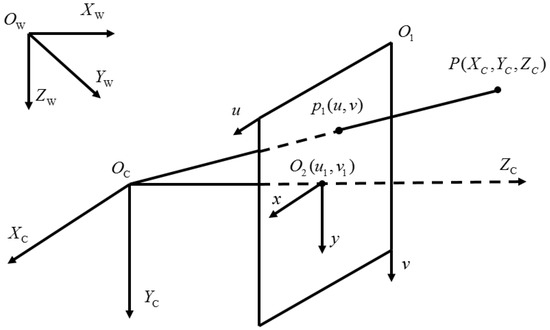
Figure 1.
Coordinate system in camera model.
In Figure 1, , represents a pixel coordinate system in which u and v represent the theoretical position of a pixel in the image, rather than their true physical position in the image. is called the optical axis, and the point at which is defined to intersect with the image plane represents the “principal point”. represents the physical coordinate system, which truly reflects the actual position of the pixel point, and the coordinate origin is the main point. In order to facilitate the mutual conversion between the pixel coordinate system and the physical coordinate system, the physical coordinate system is usually projected along the plane along the axis to construct a conversion relationship, as shown in Equation (1), , denotes the physical size of each pixel. represents the camera coordinate system, and the optical center is defined as . is the focal length of the camera. The plane in the pixel coordinate system is called the image plane. The projection point of a point P in the image plane is and in the camera coordinate system. The conversion relationship between the image coordinate system and the camera coordinate system can be obtained without considering the distortion, such as Equation (2).
The world coordinate system is constructed, in order to accurately describe the position of the camera in space and the position of the object in three-dimensional space, as shown in in Figure 1, it can be represented by a rotation matrix R and a translation matrix T, as shown in Equation (3).
The above camera imaging model is an ideal imaging model without external interference. Camera manufacturing, installation and other processes will cause a variety of errors, resulting in a variety of nonlinear distortions of the camera, in practical applications. The nonlinear distortion factors of the camera should be considered in camera calibration to correct the ideal camera imaging model, in order to enable the camera to obtain more accurate calibration results. Considering the lens distortion, there is a certain offset between the actual imaging point and the theoretical imaging point, and the offset in the x and y directions can be expressed by Equation (4), and .
The first term on the right side of Equation (4) is radial distortion; The second is centrifugal distortion; , , and , are radial and tangential distortion coefficients, respectively. Three radial distortion coefficients , , and two tangential distortion coefficients , are obtained by using the least square method, and the maximum likelihood estimation method is used for optimization to make the calibration results more accurate [10].
2.2. The Method of Camera Calibration
Camera calibration method are relatively mature technologies in the field of computer vision, and many researchers have achieved remarkable results for decades. Camera calibration technology was first applied to photogrammetry [11]. The camera is calibrated by making connections by means of mathematical parsing. With the prevalence of calibration method based on checkerboard pattern proposed by Zhang et al., many researchers have made many improvements on this basis. He et al. [12] combined with K-SVD sparse dictionary learning to construct sparse dictionary in chessboard image, and update camera changes in time to achieve high precision and high efficiency camera calibration.
Compared with monocular camera calibration, multi-camera calibration requires two or more cameras to share the same coordinate space. The relationship between the two camera coordinates sharing the same object is estimated by epipolar geometry in the process of stereo camera calibration as shown in Figure 2. The imaging coordinates of a point p in space on two camera planes and are and , we can use the basic relation to estimate the basic matrix F.
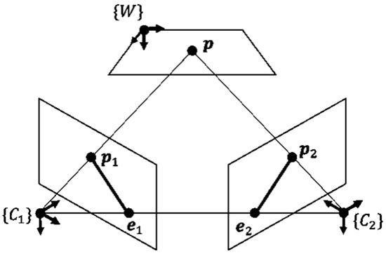
Figure 2.
Epipolar geometry.
Camera calibration is the most basic part of the visual system. In the case of complex scenes and large amount of computing, the main research content is high precision, high efficiency, high robustness, but also to consider the cost of the calibration process.
Generally, according to the spatial dimension of the calibration target, it can be divided into four categories [13]: calibration based on three-dimensional objects [14], calibration based on two-dimensional plane [3], calibration based on one-dimensional segmentation [15] and zero-dimensional self-calibration method [16]. The method used in this paper is camera calibration using a two-dimensional pattern with flexibility and ease of operation.
The two-dimensional calibration template was originally realized by detecting the square corner points. With the application of circular calibration pattern, Wang et al. [17] proposed the Pascal theorem under the circular calibration template, solved the circular point image by Newton’s iteration method, and then converted the absolute quadratic curve constraint into a Pascal line constraint to calibrate the camera internal reference, expanding the application scope of calibration. Xu et al. [18] proposed to use two intersecting coplanar circles as calibration templates, using the theory of two intersecting circles at intersection points on the projection plane and a kernel line geometry to solve the dot image, and linearly determine the internal reference by linearly determining the dot images in three images in different directions of the same pattern.
3. Proposed Method
This paper focuses on the extraction of calibration pattern of calibration circular calibration plate in the calibration process of multi-camera. After obtaining multiple groups of calibration plate pictures taken by cameras in different positions, after grayscale pre-processing, each circular pattern is divided, and the F matrix is used for sub-pixel edge extraction and circle center feature calculation. Finally, combined with Zhang’s calibration method, stereo calibration of multi-camera is carried out. The specific process is as follows in Figure 3.

Figure 3.
Camera calibration process.
3.1. Image Acquisition and Preprocessing
In this paper, three industrial USB cameras, equipped with IMX317 photosensitive chip, with an imaging size of 1.62 m × 1.62 m and a pixel of 1280 × 960, are combined together by 3D printing structural parts as Figure 4.
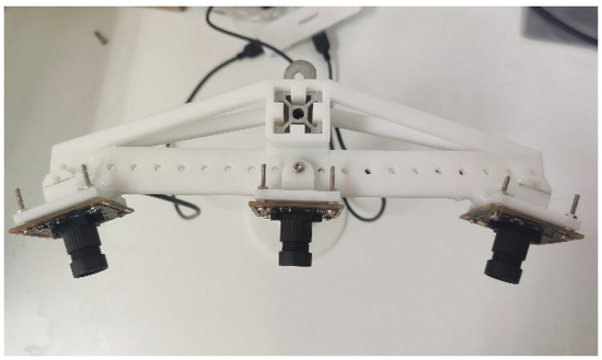
Figure 4.
Image acquisition platform.
Three cameras were used to take pictures of different positions of the circular calibration plate at the same time, and multiple calibration plate pictures were obtained, and 16 groups of original images with the best effect were screened out. Then the image is transformed into grayscale, as shown in Figure 5.
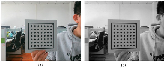
Figure 5.
Image preprocessing. (a) The original image, (b) Grayscale.
3.2. Sub-Pixel Circular Edge Detection Based on Franklin Matrix
The accuracy of edge detection of center calibration pattern directly affects the extraction of center, thus affecting the final camera calibration result. In this paper, a sub-pixel image edge detection algorithm based on Franklin moment proposed by Wu et al. is used [19]. According to the polar definition of Franklin moment, it can be seen that Franklin moment are orthogonality and rotation invariance. Because when the image is rotated by an angle the relationship between the Franklin moment after the image and the Franklin moment before rotation is Equation (5).
It can be concluded from Equation (5) that after an image is rotated, the mode of its Franklin moment will not change, only the phase angle will change. Therefore, using the feature that the image moment characteristics include the parameters of the edge model, the parameters of the edge can be estimated based on the characteristic information of the Franklin moment, so as to realize the precise positioning of the edge [20]. Franklin subpixel edge detection model is shown in Figure 6.
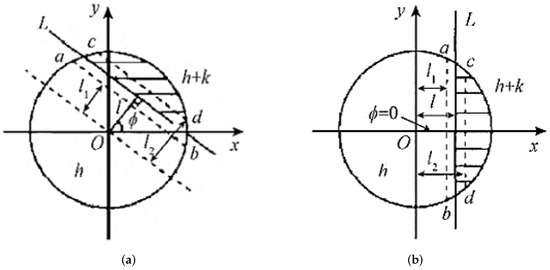
Figure 6.
Subpixel edge detection model. (a) Original edge image, (b) The rotated edge image.
In Figure 6, line L, represents the ideal edge, and the unit circle is divided into two gray regions by line L. h is the background gray level, k is the step height (gray difference), and l is the vertical distance of the center of the circle. The two dashed lines ab and cd correspond to the image edge under the conditions of Franklin moments of different orders. The specific values are given by Equations (16) and (17). is the included angle between the vertical line segment from the center of the circle to the edge and the X-axis. Figure 6b is obtained by rotating the angle clockwise from Figure 6a, where lines ab and cd are parallel to the Y-axis.
Let and represent the real part and imaginary part of , respectively, then we can get:
It can be seen from Figure 6b that the rotated image is axisymmetric about x, and it can be obtained:
The rotation angle can be easily obtained from Equation (9):
According to the template in Figure 6a, Franklin moments of each order of the rotated image can be obtained:
After the above derivation, the sub-pixel edge detection formula is derived according to Figure 6 after obtaining the key parameters , l, k [19]:
In Equation (20), is subpixel coordinates of image edges, is the coordinates of the midpoint in Figure 6a. Considering the Franklin template has N × N amplification effect, it can make the positioning more accurate. The definition of edge is as follows:
The size of the template directly affects the results of edge detection. In this paper, the 7 × 7 template for constructing Franklin moments is selected. The conventional algorithm of sub-pixel edge detection based on matrix only uses low-order moments, that is, the distance l is obtained by Equations (16) and (17), the step height k is determined by Equation (18), and the sub-pixel edge is judged according to and , where and are the threshold, and the average value of l and k matrix is obtained. Since the conventional algorithm does not consider the higher order moments, the edge lines detected are coarse, so the following edge determination conditions are used [19]:
Since and , respectively, represent the low-order and high-order of Franklin moments, this criterion combines the anti-noise characteristics of Franklin low-order moments and the detailed description ability of high-order moments, so the edge location is more accurate [19]. The main steps of calibration image sub-pixel edge detection algorithm are as follows:
Firstly, the image is grayed, and each circular calibration pattern in the calibration board is segmented. Finally, the sub-pixel edge extraction of circular calibration pattern is carried out through the above Algorithm 1 as shown in Figure 7.
| Algorithm 1: Mey steps of sub-pixel edge detection. |
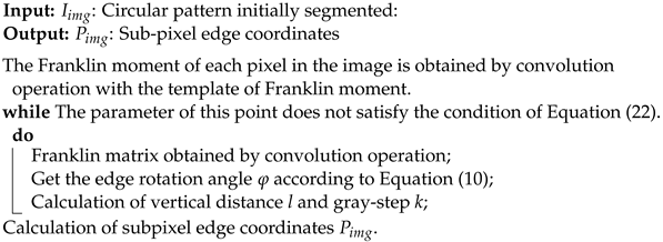 |
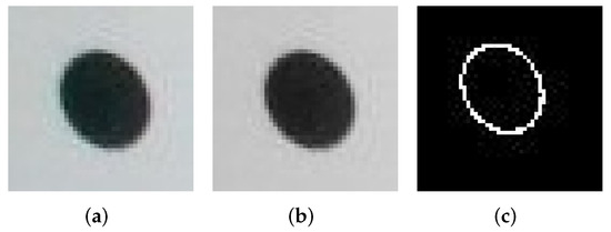
Figure 7.
Subpixel edge extraction of circular calibration pattern. (a) Original image, (b) Grayscale, (c) Edge detection.
3.3. Circular Feature Center Extraction
After obtaining the contour of the circular feature, the centroid of the feature can be obtained by using the method of image moment, and the moment of order moment is defined as:
When , represents the center of mass of the feature, and the horizontal and vertical coordinates of the center of mass are calculated as follows:
Substituting Equation (24) into Equation (23) to obtain the centroid coordinates of the feature, that is, the sub-pixel coordinates of the center of the circular feature. As shown in Figure 8, the experiment proves that the accuracy of the center coordinates obtained by this method is higher.
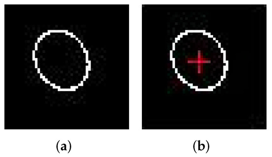
Figure 8.
Subpixel center coordinate extraction. (a) The circular edge, (b) Circle extraction.
4. Experimental Results and Analysis
4.1. Single Camera Calibration
In the experiment, the circular pattern calibration plate shown in Figure 9 was used, and the self-built multi-camera acquisition platform shown in Figure 4 was used, and the calibration plate with different attitudes and directions was first taken by three cameras at the same time, and a total of 48 photos were obtained from 3 groups. All photos are divided into circular patterns, followed by the process shown in Algorithm 1 for circular subpixel edge extraction and center coordinate calculation, to obtain the coordinate matrix of the calibration pattern in each calibration plate, and finally use the calibration algorithm in the OpenCV library for camera calibration, and obtain the internal reference matrices of the left, middle and right cameras are , , .
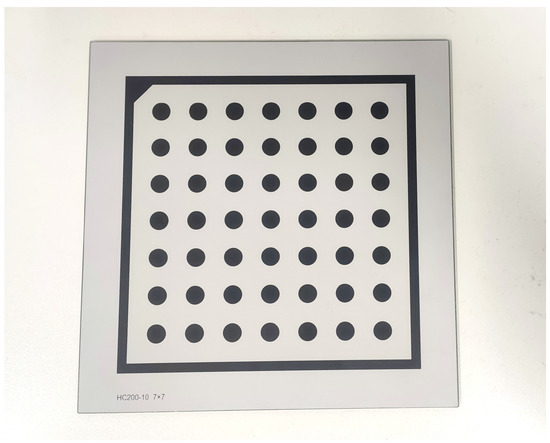
Figure 9.
Calibration board.
Internal reference matrix of left camera:
Internal reference matrix of middle camera:
Internal reference matrix of right camera:
Distortion coefficient of left camera:
Distortion coefficient of middle camera:
Distortion coefficient of right camera:
From the above experimental results, it can be seen that the and of the three cameras on the left, middle and right are close, and the radial distortion and centrifugal distortion are also small, indicating that the calibration results are accurate.
4.2. Multi-Eye Stereo Calibration
After the calibration of the monocular camera, the calibration result is calibrated for multi-eye stereoscopic calibration, that is, to solve the spatial position relationship of each camera in the camera system in the world coordinate system, that is, the rotation vector R and translation matrix T between multiple cameras need to be calculated.
Assuming that there is a point P in the real physical world, its world coordinate is , which is represented as , and , respectively, in the image acquisition system designed in this article, that is, in the left-center-right camera coordinate system. After calibrating the three cameras separately, the external reference matrix can be obtained, that is, the rotation vectors , and between the three camera coordinate systems and the world coordinate system, as well as the translation matrix , and . The coordinates of the P-point in the three camera coordinate systems can be expressed as [21,22]:
The left side of the equal sign above represents the coordinate values of the same space point P in different imaging planes. If the intermediate camera coordinate system is set as the main coordinate system, it can be obtained:
and represent rotation vector and translational matrix between left and middle camera coordinate systems. and represent the rotation vector and translational matrix between the right and middle camera coordinate systems. It can be deduced from Equation (26):
The results obtained in the above formula are the parameters to be solved in stereo calibration.
After the monocular camera calibration, the calibration results are calibrated in multi-ocular stereo, and the rotation matrix and translation matrix between the three camera coordinate systems can be obtained:
From the above stereo calibration results, it can be seen that the left and right cameras are symmetrically distributed, and at the same time have small height error in the Y-axis direction. Similarly, they have good parameters in the Z-axis direction. When imaging symmetrical objects, operations such as subsequent three-dimensional reconstruction can be better performed.
4.3. Analysis of Calibration Experiment Results
The mean value of image residual is used to measure the deviation between the original image point and the reprojection point of space point P, to determine the calibration accuracy. Where the total image residual mean is calculated as follows [23]:
In Equation (28): is the original image point coordinate of space point P; is the coordinates of the reprojection, the smaller the result in the above equation, the higher the precision of the calibration.
Figure 10a shows the results of the method proposed herein by detecting the circular edge of subpixels and then performing camera calibration with the same method using circular calibration plates proposed by Wang et al. [10].

Figure 10.
Reprojection error of intermediate camera. (a) The method proposed in this paper is compared with the same type of method; (b) The proposed method is compared with other algorithms.
From the comparison results, we can see that the reprojection error of all 16 calibration images is calculated, and the method in this paper has better calibration results. The main reason is that in the recognition process of circular pattern on the calibration image, Franklin moment can be used to extract more fine edge features, so as to obtain more accurate center coordinates.
In Figure 10b, taking the intermediate camera calibration results as an example, compared with the most widely used angle point detection and calibration algorithm in the OpenCV library, as well as the latest calibration algorithm optimized by calibration parameters, the camera calibration method based on circular calibration board proposed in this paper has achieved better calibration results in 16 calibration images. The reprojection error of most calibration images is greatly improved compared with the previous two algorithms. It can be seen from the image that the reprojection error of the second, fifth and last calibration images is slightly improved compared with the traditional method, but compared with the algorithm proposed by Tian et al. [4], the calibration effect is not satisfactory. In this paper, all the calibration patterns are re-compared and analyzed and the above three pictures are taken at a large angle. When the algorithm proposed in this paper is used to extract the center of the ellipse, the deviation of the center of the ellipse will be generated, resulting in unsatisfactory calibration results [8]. Therefore, when using the calibration method proposed in this paper, it has good calibration effect in the case of small shooting angles.
Table 1 shows the comparison between the camera calibration method proposed in this paper and the traditional calibration method using checkerboard grids, the calibration method optimized by the latest calibration results [4], and the calibration method proposed by Wang et al. [10]. that also uses circular calibration plates. Among them, the left, center and right represent the cameras in the three positions in Figure 4.

Table 1.
Mean value of image residual (pixels).
As can be seen from Table 1, for the three-camera image acquisition platform built in this paper, The method in the table is used to calibrate. From the mean analysis of the calibration results, this paper proposes that the camera calibration method has better results, and the performance on the middle and right cameras is better. Although the calibration result of the left camera is greatly improved compared with the calibration method proposed by Wang et al. [10], it has worse results than the traditional method. The analysis of this reason is consistent with the previous analysis of the calibration results of a single camera. In the shooting process of the calibration image, all the cameras are triggered at the same time. Due to the relationship between the position of the calibration plate, the calibration image obtained by some cameras will have a large angle. A standard circular pattern will become an elliptical image after imaging, thus introducing the eccentricity error, resulting in poor calibration results of some cameras. However, in terms of the calibration results of all cameras, the proposed method has significantly improved the accuracy, and the average reprojection error of three cameras is reduced by more than 0.006 pixels, which verifies the feasibility and superiority of the proposed method.
5. Conclusions
In this paper, a stereo calibration method for multi-camera based on circular calibration plate is proposed. The method focuses on the high-precision extraction of calibration pattern features in the calibration process. Multiple images of circular calibration plate are collected by self-matching three-camera image acquisition system. The Franklin matrix was used to detect the sub-pixel edge of the circle and extract the center of the characteristic circle. Finally, Zhang’s calibration method was used for camera calibration and multi-view stereo calibration. The experimental results show that the calibration accuracy of the three cameras is effectively improved compared with the relevant calibration algorithms. Although the effect on the large angle calibration pattern is not superior to the traditional method, but there is better accuracy in the image acquisition platform of the three camera, and the average re-projection error is reduced by more than 0.006 pixels, and a better calibration effect is achieved.
Author Contributions
Conceptualization, X.L. and J.T.; methodology, X.L.; experiment, J.T.; validation, H.K.; data analysis, X.M.; original draft preparation, H.K. and X.M. All authors have read and agreed to the published version of the manuscript.
Funding
This work was supported by the National Natural Science Foundation of China (No. 29961772088).
Conflicts of Interest
The authors declare no conflict of interest.
References
- Guan, J.; Deboeverie, F.; Slembrouck, M.; Van Haerenborgh, D.; Van Cauwelaert, D.; Veelaert, P.; Philips, W. Extrinsic calibration of camera networks using a sphere. Sensors 2015, 15, 18985–19005. [Google Scholar] [CrossRef] [PubMed] [Green Version]
- Yang, S. A Research of Industrial Camera Calibration System Based on Halcon. Master’s Thesis, Yangtze University, Jingzhou, China, 2021. [Google Scholar]
- Zhang, Z. A flexible new technique for camera calibration. IEEE Trans. Pattern Anal. Mach. Intell. 2000, 22, 1330–1334. [Google Scholar] [CrossRef] [Green Version]
- Tian, S.B.; Fan, J.L.; Wang, Z.; Duan, J.S. Monocular Camera Calibration Algorithm Based on Improved Particle Swarm Optimization Algorithm. Ship Electron. Eng. 2021, 41, 44–47, 154. [Google Scholar]
- Heikkila, J.; Silvén, O. A four-step camera calibration procedure with implicit image correction. In Proceedings of the IEEE Computer Society Conference on Computer Vision and Pattern Recognition, San Juan, Puerto Rico, 17–19 June 1997; pp. 1106–1112. [Google Scholar]
- Shan, B.H.; Yuan, W.T.; Liu, Y. A Calibration Method for Stereovision System Based on Solid Circle Target. Acta Opt. Sin. 2016, 132, 225–234. [Google Scholar] [CrossRef]
- Chen, B.; Pan, B. Camera calibration using synthetic random speckle pattern and digital image correlation. Opt. Lasers Eng. 2020, 126, 105919. [Google Scholar] [CrossRef]
- Zhou, Y.Q.; Xue, H.R.; Jiang, X.H. An Camera Calibration Method Base on Circular Feature Points. J. Inn. Mong. Agric. Univ. Sci. Ed. 2014, 35, 155–159. [Google Scholar]
- Sonka, M.; Hlavac, V.; Boyle, R. Image Processing, Analysis, and Machine Vision; Cengage Learning: Boston, MA, USA, 2014. [Google Scholar]
- Wang, S.K.; Zhao, J.Z.; Jiang, M.; Wang, H.T.; Zhang, Y.D. Zhang’s Camera Calibration Method Based on Circular Array Calibration Board. Trans. Beijing Inst. Technol. 2019, 39, 859–963. [Google Scholar]
- Abdel-Aziz, Y.I.; Karara, H.; Hauck, M. Direct linear transformation from comparator coordinates into object space coordinates in close-range photogrammetry. Photogramm. Eng. Remote Sens. 2015, 81, 103–107. [Google Scholar] [CrossRef]
- He, H.; Li, H.; Huang, Y.; Huang, J.; Li, P. A novel efficient camera calibration approach based on K-SVD sparse dictionary learning. Measurement 2020, 159, 107798. [Google Scholar] [CrossRef]
- Wu, F.; Hu, Z.; Zhu, H. Camera calibration with moving one-dimensional objects. Pattern Recognit. 2005, 38, 755–765. [Google Scholar] [CrossRef]
- Heikkila, J. Geometric camera calibration using circular control points. IEEE Trans. Pattern Anal. Mach. Intell. 2000, 22, 1066–1077. [Google Scholar] [CrossRef] [Green Version]
- Fu, Z.L.; Zhou, F.; Xie, Y.F.; Qin, Y. One-Dimensional multi-camera calibration based on fundamental matrix. Acta Opt. Sin. 2013, 33, 0615003. [Google Scholar]
- Jin, J.; Li, X. Efficient camera self-calibration method based on the absolute dual quadric. JOS Am. A 2013, 30, 287–292. [Google Scholar] [CrossRef] [PubMed]
- Wang, X.; Zhao, Y.; Yang, F. Camera calibration method based on Pascal’s theorem. Int. J. Adv. Robot. Syst. 2019, 16, 1729881419846406. [Google Scholar] [CrossRef] [Green Version]
- Chen, X.; Zhao, Y.; Fu, S. Linear determination of a camera’s intrinsic parameters using two intersecting circles. Int. J. Adv. Robot. Syst. 2014, 11, 38. [Google Scholar] [CrossRef] [Green Version]
- Wu, Y.Q.; Zou, Y.; Liu, Z.L. Sub-pixel Level Image Edge Detection Algorithm Based on Franklin Moments. Chin. J. Sci. Instrum. 2019, 61, 436–446. [Google Scholar]
- Da, F.; Zhang, H. Sub-pixel edge detection based on an improved moment. Image Vis. Comput. 2010, 28, 1645–1658. [Google Scholar] [CrossRef]
- Yin, W.Q. Research on Calibration Method of Binocular Vision. Master’s Thesis, Xi’an University of Technology, Xi’an, China, 2021. [Google Scholar]
- Lee, Y.J.; Park, M.W. 3D tracking of multiple onsite workers based on stereo vision. Autom. Constr. 2019, 98, 146–159. [Google Scholar] [CrossRef]
- Wang, X.; Zhao, Y.; Yang, F. Camera calibration using projection properties of conics of equal eccentricity. J. Mod. Opt. 2021, 68, 670–678. [Google Scholar] [CrossRef]
Publisher’s Note: MDPI stays neutral with regard to jurisdictional claims in published maps and institutional affiliations. |
© 2022 by the authors. Licensee MDPI, Basel, Switzerland. This article is an open access article distributed under the terms and conditions of the Creative Commons Attribution (CC BY) license (https://creativecommons.org/licenses/by/4.0/).