Abstract
As an efficient information processing method, reservoir computing (RC) is essential to artificial neural networks (ANNs). Via the Santa Fe time series prediction task, we numerically investigated the effect of the mismatch of some critical parameters on the prediction performance of the RC based on two mutually delay-coupled semiconductor lasers (SLs) with optical injection. The results show that better prediction performance can be realized by setting appropriate parameter mismatch scenarios. Especially for the situation with large prediction errors encountered in the RC with identical laser parameters, a suitable parameter mismatch setting can achieve computing performance improvement of an order of magnitude. Our research is instructive for the hardware implementation of laser-based RC, where the parameter mismatch is unavoidable.
1. Introduction
In modern society, with a rapidly increasing amount of information, reservoir computing (RC) has attracted more and more attention as an efficient information processing method [1,2]. RC initially evolves from two kinds of recurrent neural networks (RNNs), i.e., echo state network (ESN) and liquid state machine (LSM) [3,4]. Due to the particular network structure, RC overcomes the disadvantages of RNN, such as the complex network structure and the difficulty in training the weights of inter-layer links [5]. The topology of a complete RC is composed of three parts: an input layer, a reservoir layer, and an output layer. In the input layer, the input information is preprocessed by masks, the reservoir layer maps the input information to a high-dimensional state space, and the output layer classifies and recognizes the information in the high-dimensional state space after training. The difference between RC and RNN is that in RC, only the weight of the output layer needs to be trained, while the connection weight between the input layer and the reservoir layer and the connection weight between the internal nodes in the reservoir layer are fixed. This simplified structure improves the RC training speed and proposes a new low-energy and high-efficiency information processing scheme [6]. At present, RC has been applied in many complex tasks, including chaotic time series prediction [7,8,9,10,11], nonlinear channel equalization [12], waveform recognition task [13], and modulation format identification in fiber communications [14].
An RC system based on a time-delay configuration named delay-based RC was proposed by Appeltant et al. in 2011 [15]. In delay-based RC, the reservoir layer consists of a single nonlinear dynamical node and a delayed feedback loop. Virtual nodes are sampled equidistantly on the delay feedback loop using time-division multiplexing instead of conventional physical nodes. This simplified structure accelerates the hardware process of the RC [16]. Various delay-based RC structures, such as all-optical-feedback-based RC [7,13,14,15,16,17,18,19,20,21,22] and optoelectronic-feedback-based RC [23,24,25,26], have been extensively studied in the past decade. The all-optical-feedback-based RC carries information by photons, which may allow for low power consumption and high-speed computing [27,28]. In addition, the mutually delay-coupled semiconductor lasers (SLs) with optical injection can provide a richer dynamic response, which is beneficial for the RC to efficiently complete the simultaneous processing of multiple tasks [20,29,30,31,32,33,34]. In 2017, Pesquera et al. proposed to use the mutually delay-coupled structure as the nonlinear node of the delay-based RC [34]. Hou et al. proposed the RC system based on mutually delay-coupled SLs with optical injection and extended it to parallel task processing [30,31]. Liang et al. designed parallel RC consisting of mutually-coupled SLs with optoelectronic feedback [32]. Although previous studies have made significant improvements to RC based on mutually delay-coupling structures, the influence of the parameter mismatch on RC performance has not been discussed systematically. Parameter mismatch between the two lasers is unavoidable, even though they are grown from the same wafer [33]. Some external factors, such as fiber loss and temperature also cause the parameter mismatch. In this work, we systematically studied the effect of parameter mismatch on the computing performance of RC based on mutually delay-coupled SLs with optical injection. We aimed to assess whether proper parameter mismatch settings can improve the prediction performance of RC. We performed a systematical study on various parameter mismatch settings of the injected current, coupling strength, coupling delay, frequency detuning, as well as some internal parameters and performed computing tests using the Santa Fe time series prediction task. Simulation results show that appropriate parameter mismatch settings can indeed improve the prediction performance of the RC by more than an order of magnitude.
This paper is organized as follows. The RC system based on mutually delay-coupled SLs with optical injection is described in Section 2. The Santa Fe time series prediction task is described in Section 3. Section 4 presents the prediction results of the RC with different parameter mismatch settings, including the injection current, coupling strength, coupling delay, frequency detuning, and some internal parameters. Finally, we summarize the results in Section 5.
2. Reservoir Computing System
The system we used to address the influence of the parameter mismatch on the RC performance is shown in Figure 1. This system takes two mutually delay-coupled SLs (SL1 and SL2) as a reservoir. The drive laser (DL) is used to achieve the consistency of the mutually delay-coupled SLs and send the input signal into the reservoir by loading the input signal into the injection light from the DL, similar to the structure reported in [31]. The RC system consists of the input layer, reservoir layer, and output layer. In the input layer, the input signalis a set of discrete time series, where n is the time series index. Two different mask signals (mask1 and mask2) preprocess the input signal with Mach–Zehnder modulation (MZM). Here, a chaotic signal as the mask of the input signal is generated by semiconductor lasers with external cavity feedback [9]. The mask signal is combined withto form the input data stream. In the reservoir layer, SL1 and SL2 are mutually delay-coupled by the coupling time-delay (red) and (blue), where each laser acts as a reservoir. In the simulation, we consider the scenario of the parameter mismatch between two SLs, including the injection current, coupling strength, coupling delay, frequency detuning, and internal parameters; we set the node interval between the adjacent nodesand the number of virtual nodes in each reservoir is N. Therefore, the total number of virtual nodes in the system is 2N. The sampling period of the input signal is T, where. Unless otherwise indicated, we assume that.
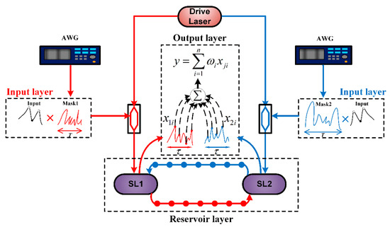
Figure 1.
Schematic diagram of RC based on two mutually delay-coupled SLs (SL1 and SL2) with optical injection, where the mask signals are different for SL1 and SL2.
The output of the mutually delay-coupled SLs is sampled according to the node interval θ, and the virtual node states are represented byand. Because of the combined effect of the different masks used in the input layer and the mismatched parameters between SL1 and SL2, the virtual node states in the two delay lines are different. In order to ensure that the system outputs a complex response, θ should be smaller than the transient response of the laser [9]. The nonlinear dynamics of mutually delay-coupled lasers, i.e., SL1 and SL2, with optical injection can be described by [35,36]:
where subscripts 1 and 2 represent SL1 and SL2. E represents the slowly varying complex electric field of lasers, and N represents the carrier number in the laser cavity.is the saturation coefficientis the gain coefficient;is the linewidth enhancement factor;is the carrier density at transparency;andare the photon and carrier lifetimes, respectively; are the mutual coupling strengths (SL2 to SL1 and SL1 to SL2);are the normalized injection currents of the two SLs;is the injection current at the lasing threshold;is the injection strength from the DL to mutually delay-coupled lasers;is the frequency of the free-running SL1 and SL2;is the frequency detuning between mutually delay-coupled SLs; andis the frequency detuning between the DL and SL1 (SL2). To focus on the effect of the optimization capability of the parameter mismatch on the prediction performance of the RC, spontaneous emission noise was not taken into account in this work [37]. The injected slowly varying complex electric fieldof mutually delay-coupled lasers can be written as:
whereis the steady intensity of the DL, and the mask input signalcan be described as:
whereis the input data,is the mask signals of SL1 and SL2 with periodicity T, and γ is the scaling factor.
3. Santa Fe Time Series Prediction Task
In this study, the Santa Fe time series prediction task was employed to evaluate the influence of the parameter mismatch on the computing performance of the RC based on two mutually delay-coupled lasers. This task is often used to test the prediction performance of machine learning systems to predict chaotic time series. The Santa Fe time series data contain 4000 points generated from a far-infrared laser. The first 3000 points were used for training the RC and the next 1000 points for testing. The normalized mean square error (NMSE) was used to evaluate the prediction performance of the RC, which can be described as [8]:
where and are the target value and the predicted value of the reservoir, respectively. L is the total number of the datasets, and n is the time index of the input data. Usually, the performance of the RC system is acceptable when NMSE < 0.1 [8,13,21,22,31,32,38,39].
4. Numerical Results and Discussion
In the simulation, a fourth-order Runge–Kutta algorithm was used to solve Equations (1) and (2) with a time step of 2 ps. The definitions and values of the symbols used in the simulation are shown in Table 1. In the following, we assume that SL1 and SL2 have the same parameters unless otherwise stated. We mainly focus on the influence of the mismatch of the injection current, coupling strength, coupling time-delay, frequency detuning, and internal parameters () on the prediction performance.

Table 1.
Parameter values were used in the numerical simulation.
To begin with, Figure 2 shows an example of the prediction results for the parameters of SL1 and SL2 without and with the mismatch, when and. Figure 2(a1–c1) presents the results for the case without parameter mismatch, where the predicted signal is obviously different from the original one and the estimated NMSE is 0.1485. In contrast, as shown in Figure 2(a2–c2), when a certain parameter mismatch is introduced, i.e., , , and , the original and predicted signals are almost identical, leading to a much smaller value of NMSE of 0.0049. This indicates that, by appropriately setting the parameter mismatch, the NMSE can be reduced by more than an order of magnitude. The reason for the improvement of RC prediction results of parameter mismatch is that when and, the dynamic state of the mutually delay-coupled SLs is the periodic state. After setting a suitable parameter mismatch, the dynamic state of SLs changes from the periodic state to the steady state point near the bifurcation point. In previous studies, RC achieved good computational performance when SLs operated in these states [15,31]. Compared with some existing classical RC systems, the RC based on mutually delay-coupled SLs has some advantages in computing performance after setting suitable parameter mismatch [16,32,38].
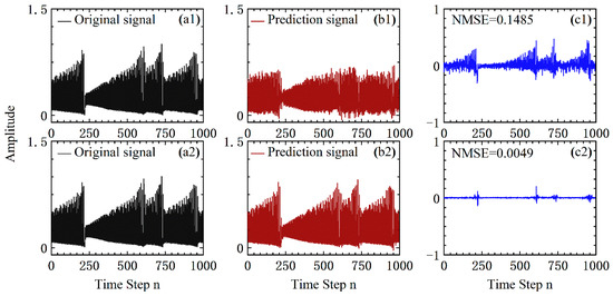
Figure 2.
(a1,a2) The original signal, (b1,b2) the predicted signal, and (c1,c2) the prediction error and the estimated NMSE. (a1–c1) SL1 and SL2 with identical parameters, i.e., and, (a2–c2) SL1 and SL2 with mismatched parameters, i.e., , , and .
4.1. The Parameter Mismatch of Injection Current and Coupling Strength
In this section, we outline the influence of the mismatched injection current () and coupling strength () on the RC prediction performance and compare their prediction errors with the case of identical parameter settings.
We first investigated the optimization capability of the injection current mismatch on the RC prediction performance. Here, four cases, in which the coupling strength of the reservoir was set to 15, 20and 25, are taken as examples. All the following data were calculated 10 times under random initial conditions and then averaged. The dependence of the NMSE onis presented in Figure 3, when and . The injection current mismatch ratio can be measured by(). In Figure 3, with the increase in, the NMSE gradually decreases before reaching its minimum value and then increases after. More specifically, as shown in Figure 3a, the prediction error of RC is reduced when, while in Figure 3b–d, when, the NMSE becomes less than the prediction error with . These results indicate that the NMSE is highly dependent on the mismatched ratio of the injection current. In the case of poor prediction performance (NMSE > 0.1) for the identical injection current, the proper mismatch can improve the RC prediction performance more obviously. For example, in Figure 3d, the mismatch of the injection current can improve the NMSE from the unacceptable value (NMSE > 0.1) to a desired one (NMSE < 0.01), which may achieve the improvement of more than an order of magnitude. Therefore, the prediction performance can be improved for this RC system with appropriate injection current mismatch.
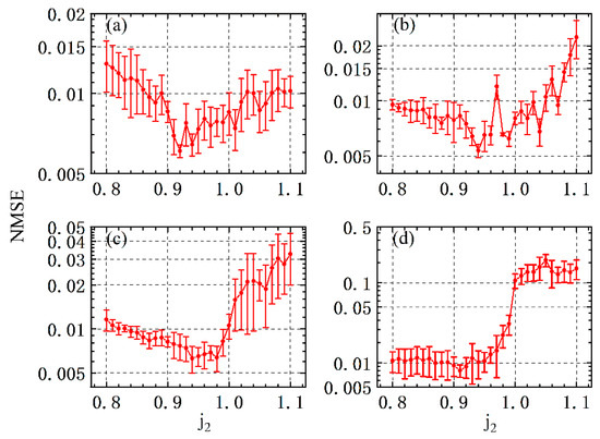
Figure 3.
NMSE of chaotic time series task as a function of the normalized injection currentof SL2, where (a), (b), (c), and (d).
Furthermore, we analyzed the influence of the coupling strength on the RC performance. Figure 4 illustrates the NMSE as a function of the coupling strength from SL1 to SL2 (). The identical injection current () and the coupling strength from SL2 to SL1 () were set to (0.85, 10), (0.95, 15), and (1.05, 20), respectively. The mismatch ratio of the coupling strength can be measured by (). As can be seen from Figure 4, the mismatch of the coupling strength between SL1 and SL2 can affect the prediction performance of the RC when varies over a large range. However, it is difficult to improve the computing performance by deliberately mismatching the coupling strength, i.e., introducing the asymmetric coupling scheme, since the NMSE variation is very limited for the considered mismatch ratio as shown in Figure 4.
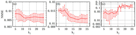
Figure 4.
NMSE as a function of the coupling strength, where (a); (b); and (c).
The above results demonstrate that better performance can be achieved for the RC based on mutually delay-coupled lasers with certain mismatch settings of the injection current () and the coupling strength (). In the following, we explore the influence of and mismatch on the RC performance. Figure 5a shows the two-dimensional (2D) map of the NMSE with identical parameter settings in the parameter space of versus , where the blank regions represent NMSE > 0.1; that is, the dynamic state of the mutually delay-coupled SLs corresponding to the parameter plane in this region is the periodic state. The dotted curves correspond to NMSE = 0.01, while the areas confined by these NMSE = 0.01 dotted curves represent NMSE < 0.01. More specifically, the blue and purple regions in Figure 5 represent the good performance (NMSE < 0.01) of the RC, where the dynamic state is the steady state near the bifurcation point. In Figure 5a, one can obtain good performance by properly adjusting the coupling strength and/or the injection current, even though those parameters are identical for the two lasers. Figure 5b shows the mapping of the NMSE for the constant parameter mismatch with, in the () plane. Compared with Figure 5a, the area for NMSE > 0.1 almost disappears because the parameter mismatch changes the dynamic state in the region of NMSE > 0.1 from the periodic state to the steady state. The size of the areas for NMSE < 0.01 is significantly reduced. That is to say, by setting the fixed mismatch in the entire plane, one can expect not only the improvement of the prediction performance in the region of NMSE > 0.1 but also the smaller size of the area corresponding to NMSE < 0.01. The 2D map of the NMSE for the parameter mismatch specified in Table 2 is shown in Figure 5c. By comparing Figure 5c with Figure 5b, it can be seen that the dynamic parameter mismatch settings in the different plane can compensate for the degradation of the prediction performance caused by the fixed parameter mismatch, and better optimize the prediction performance in the region of NMSE > 0.1. In other words, suitable parameter mismatch settings for differentand can further improve the prediction performance of the RC.
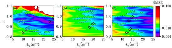
Figure 5.
2D map for logarithm of NMSE as functions of the injection currentand coupling strength. (a); (b); and (c) the dynamic parameter mismatch settings listed in Table 2 in different plane.
Table 2.
Mismatch scheme of dynamic parameter mismatch.
4.2. The Parameter Mismatch of Coupling Time-Delay
In this section, we outline the prediction performance of the RC in the case of mismatching the mutual coupling time-delay. Figure 6 shows the variation of NMSE with the parameter mismatch ratio Here, three different cases with and variable are presented, in which the injection current and coupling strength of the SL1 and SL2 are set toand, respectively. Here, the is measured by, where () is the coupling time-delay from SL2 (SL1) to SL1 (SL2). As shown in Figure 6a, the improvement of computing performance by mismatching the mutual coupling time-delay is very limited. In Figure 6b,c, the minimum values of the NMSE are 0.0087 and 0.0105 when , respectively. Additionally, one can also observe the periodic property associated with the parameter mismatch ratio, especially in Figure 6b,c. In Figure 6c, the dynamic state of mutually delay-coupled SLs varies among the chaotic state, the periodic state, as well as the steady state as the parameter mismatch ratio is adjusted. The above results demonstrate that the prediction performance improvement can be achieved by employing two asymmetric coupling delay times between the two mutually coupled lasers.
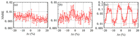
Figure 6.
NMSE of chaotic time series task as a function of the mismatch of coupling time-delay. (a); (b); and (c).
We introduced coupling delay mismatch and scanned the NMSE in the parameter space of j versus k, where. The 2D map of the NMSE with is shown in Figure 7. In this diagram, we can see that the size of the area corresponding to NMSE < 0.01 exceeds that with the identical parameter setting in Figure 5a. Unlike the phenomena in Figure 5b,c, the coupling time-delay mismatch cannot degrade the prediction performance of NMSE < 0.01 for the identical parameter setting.
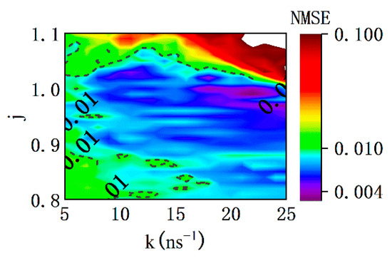
Figure 7.
2D map for logarithm of NMSE as functions of injection current j and coupling strength k in the case of−8%.
4.3. The Mismatch of Internal Parameters
In this section, we evaluate the influence of the mismatch of some internal parameters in SL1 and SL2 on the RC performance. We assume that the internal parameters of the SL1 are kept unchanged, and those of the SL2 are varied according to the mismatch ratio. For a specific parameter, we have the mismatch ratios for the linewidth enhancement factor, the gain coefficient, the photon lifetime , the carrier lifetime, and the carrier density at transparency. Figure 8 and Figure 9 display the NMSE as a function of the internal parameter mismatch ratio between SL1 and SL2 for several values ofand. The error bars are not included in Figure 8 and Figure 9 for clarity. As can be seen from both figures, the NMSE is highly dependent on the mismatch ratio and the coupling strength. For and better performance is expected for larger when mismatch ratio (see Figure 8 and Figure 9a), while for , better performance can be achieved for the largerwhen(see Figure 9b). The reason is that the dynamics state of mutually delay-coupled SLs is transformed from the periodic state to the steady state with the increase in the absolute mismatch ratio . More importantly, it is possible to greatly enhance the computing performance by introducing the internal parameter mismatch during the laser design. For example, whenin Figure 9a, the NMSE is larger than 0.1 for no mismatch, whereas it is decreased to below 0.01 for −10%. For the predicted results of NMSE > 0.1 in Figure 8 and Figure 9, the prediction error can be reduced by simply increasing the injection intensity from the DL to mutually delay-coupled SLs, which enrich the design of the internal parameter of SLs in the experiment [40].
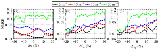
Figure 8.
NMSE as a function of the mismatch ratio of the internal parameters for several values of and, where (a) corresponds to the mismatch of, (b) to the mismatch of, and (c) to the mismatch of.
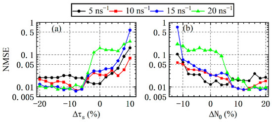
Figure 9.
NMSE as a function of the mismatch ratio of the internal parameters for several values of and, where (a) corresponds to the mismatch of and (b) to the mismatch of.
The above results demonstrate that the prediction performance can be improved by the mismatch of some internal parameters of two mutually delay-coupled SLs. Without loss of generality, we scanned the NMSE for RC in a parameter space of j and k when the mismatch ratio of, was −5%, −10%, −20% and is 5%, 10%, 20%. The results are shown in Figure 10. Compared with the blank region (NMSE > 0.1) in Figure 5a, all of the three mismatch settings of internal parameters considered are able to optimize the NMSE from 0.1 to 0.001. Compared with Figure 7, the optimization ability of the internal parameter mismatch is better than the coupling delay mismatch when NMSE > 0.1. However, with the three internal parameter mismatch settings, the area of NMSE < 0.01 is reduced compared with that for identical parameter settings in Figure 5a. With the increase in the mismatch ratio, the size of the area of NMSE < 0.01 gradually shrinks.
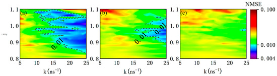
Figure 10.
2D map for logarithm of NMSE as functions of injection current j and coupling strength k for several mismatch ratios, where (a) = 5%., (b) = 10% and (c) = 20%.
Finally, we investigated the optimization ability of the RC prediction performance by introducing the internal parameter mismatch and considering the frequency detuning between two SLs. The mismatch scheme is consistent with Figure 10. The values of the frequency detuning can be measured by, (). Figure 11 illustrates the NMSE as a function of the frequency detuning forand various. For(Figure 11a), the NMSE is always less than 0.1 except for in the case offrom 5 to , and some sharp fluctuations can be seen in all curves, which means that the computing performance is sensitive to the selection of the frequency detuning. Three mismatch ratios were considered, i.e.,of 5%, 10% and 20%, as shown in Figure 11b–d, respectively. With the increase in, all of the NMSE curves with the frequency detuning become flat gradually, and the local peaks of the NMSE, e.g., at, gradually decrease and finally disappear. The minimum value of NMSE in the frequency detuning range , however, gradually increases (deteriorates). The above analysis shows that the frequency detuning between the two lasers can optimize the prediction performance of the reservoir. When the internal parameter mismatch is introduced at the same time, the minimum value of the NMSE increases with the increase in the mismatch ratio, which is consistent with the conclusion in Figure 10. The local prediction performance degradation caused by the frequency mismatch can be almost eliminated by setting a large internal parameter mismatch.
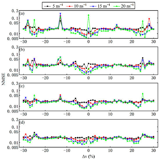
Figure 11.
NMSE as a function of the frequency detuning for several values of and with the internal parameter mismatch, where (a), (b), (c), and (d).
5. Conclusions
In summary, we numerically investigated the optimization capability of the parameter mismatch on the computing performance of the RC based on two mutually delay-coupled SLs with optical injection. In this study, the prediction performance of the RC was evaluated with the Santa Fe time series prediction task. The simulation results show that a suitable setting of the parameter mismatch of the injection current and the coupling strength between SL1 and SL2 can optimize the poor prediction result of RC (NMSE > 0.1) to a good range (NMSE < 0.01). In the case of NMSE > 0.1, the mutual coupling delay-time mismatch and the internal parameter mismatch between SL1 and SL2 can reduce the prediction error. Additionally, some good prediction performance is degraded with the fixed mismatch of the injection current and coupled strength in the entire parameter space ofversus, whereas certain dynamic parameter mismatch settings of the injection current and coupling strength can alleviate this phenomenon to some extent. The computing performance is also sensitive to the frequency detuning, which can be manipulated by introducing a proper mismatch of the laser parameters. Therefore, our research will be helpful for designing and optimizing the RC based on two mutually delay-coupled SLs with optical injection in practical applications.
Author Contributions
D.C., Y.Y. and N.L. contributed to the idea and the writing of the manuscript. P.Z. and N.L. contributed to the reviewing and editing of the manuscript. All authors have read and agreed to the published version of the manuscript.
Funding
This study was funded by National Natural Science Foundation of China (62004135, 62001317, 62171305); Natural Science Research Project of Jiangsu Higher Education Institutions of China (20KJA416001, 20KJB510011); and Natural Science Foundation of Jiangsu Province (BK20200855).
Institutional Review Board Statement
Not applicable.
Informed Consent Statement
Not applicable.
Data Availability Statement
Not applicable.
Conflicts of Interest
The authors declare no conflict of interest.
References
- Jaeger, H.; Haas, H. Harnessing nonlinearity: Predicting chaotic systems and saving energy in wireless communication. Science 2004, 304, 78–80. [Google Scholar] [CrossRef] [PubMed]
- Caulfield, H.J.; Dolev, S. Why future supercomputing requires optics. Nat. Photonics 2010, 4, 261–263. [Google Scholar] [CrossRef]
- Bao, X.; Zhao, Q.; Yin, H. Efficient optoelectronic reservoir computing with three-route input based on optical delay lines. Appl. Opt. 2019, 58, 4111–4117. [Google Scholar] [CrossRef] [PubMed]
- Maass, W.; Natschlager, T.; Markram, H. Real-time computing without stable states: A new framework for neural computation based on perturbations. Neural Comput. 2002, 14, 2531–2560. [Google Scholar] [CrossRef]
- Pearlmutter, B.A. Gradient calculations for dynamic recurrent neural networks: A survey. IEEE Trans. Neural Netw. 1995, 6, 1212–1228. [Google Scholar] [CrossRef]
- Kitayama, K.I.; Notomi, M.; Naruse, M.; Inoue, K.; Kawakami, S.; Uchida, A. Novel frontier of photonics for data processing—Photonic accelerator. APL Photonics 2019, 4, 090901. [Google Scholar] [CrossRef]
- Brunner, D.; Soriano, M.C.; Mirasso, C.R.; Fischer, I. Parallel photonic information processing at gigabyte per second data rates using transient states. Nat. Commun. 2013, 4, 1364. [Google Scholar] [CrossRef] [PubMed]
- Nguimdo, R.M.; Verschaffelt, G.; Danckaert, J.; Van der Sande, G. Fast photonic information processing using semiconductor lasers with delayed optical feedback: Role of phase dynamics. Opt. Express 2014, 22, 8672–8686. [Google Scholar] [CrossRef] [PubMed]
- Nakayama, J.; Kanno, K.; Uchida, A. Laser dynamical reservoir computing with consistency: An approach of a chaos mask signal. Opt. Express 2016, 24, 8679–8692. [Google Scholar] [CrossRef]
- Penkovsky, B.; Porte, X.; Jacquot, M.; Larger, L.; Brunner, D. Coupled Nonlinear Delay Systems as Deep Convolutional Neural Networks. Phys. Rev. Lett. 2019, 123, 054101. [Google Scholar] [CrossRef]
- Guo, X.X.; Xiang, S.Y.; Zhang, Y.H.; Lin, L.; Wen, A.J.; Hao, Y. Polarization Multiplexing Reservoir Computing Based on a VCSEL With Polarized Optical Feedback. IEEE J. Sel. Top. Quantum Electron. 2020, 26, 1–9. [Google Scholar] [CrossRef]
- Yue, D.; Wu, Z.; Hou, Y.; Cui, B.; Jin, Y.; Dai, M.; Xia, G. Performance optimization research of reservoir computing system based on an optical feedback semiconductor laser under electrical information injection. Opt. Express 2019, 27, 19931–19939. [Google Scholar] [CrossRef] [PubMed]
- Yang, Y.G.; Zhou, P.; Mu, P.H.; Li, N.Q. Time-delayed reservoir computing based on an optically pumped spin VCSEL for high-speed processing. Nonlinear Dyn. 2022, 107, 2619–2632. [Google Scholar] [CrossRef]
- Cai, Q.; Guo, Y.; Li, P.; Bogris, A.; Shore, K.A.; Zhang, Y.; Wang, Y. Modulation format identification in fiber communications using single dynamical node-based photonic reservoir computing. Photonics Res. 2020, 9, B1–B8. [Google Scholar] [CrossRef]
- Appeltant, L.; Soriano, M.C.; Van der Sande, G.; Danckaert, J.; Massar, S.; Dambre, J.; Schrauwen, B.; Mirasso, C.R.; Fischer, I. Information processing using a single dynamical node as complex system. Nat. Commun. 2011, 2, 468. [Google Scholar] [CrossRef]
- Sugano, C.; Kanno, K.; Uchida, A. Reservoir Computing Using Multiple Lasers With Feedback on a Photonic Integrated Circuit. IEEE J. Sel. Top. Quantum Electron. 2020, 26, 150040. [Google Scholar] [CrossRef]
- Duport, F.; Schneider, B.; Smerieri, A.; Haelterman, M.; Massar, S. All-optical reservoir computing. Opt. Express 2012, 20, 22783–22795. [Google Scholar] [CrossRef]
- Nguimdo, R.M.; Lacot, E.; Jacquin, O.; Hugon, O.; Van der Sande, G.; Guillet de Chatellus, H. Prediction performance of reservoir computing systems based on a diode-pumped erbium-doped microchip laser subject to optical feedback. Opt. Lett. 2017, 42, 375–378. [Google Scholar] [CrossRef]
- Huang, Y.; Zhou, P.; Yang, Y.; Chen, T.; Li, N. Time-Delayed Reservoir Computing Based on a Two-Element Phased Laser Array for Image Identification. IEEE Photonics J. 2021, 13, 1–9. [Google Scholar] [CrossRef]
- Sozos, K.; Mesaritakis, C.; Bogris, A. Reservoir Computing Based on Mutually Injected Phase Modulated Semiconductor Lasers as a Monolithic Integrated Hardware Accelerator. IEEE J. Quantum Electron. 2021, 57, 1–7. [Google Scholar] [CrossRef]
- Yue, D.Z.; Wu, Z.M.; Hou, Y.S.; Hu, C.X.; Jiang, Z.F.; Xia, G.Q. Reservoir Computing Based on Two Parallel Reservoirs Under Identical Electrical Message Injection. IEEE Photonics J. 2021, 13, 7800311. [Google Scholar] [CrossRef]
- Huang, Y.; Zhou, P.; Yang, Y.; Li, N. High-speed photonic reservoir computer based on a delayed Fano laser under electrical modulation. Opt. Lett. 2021, 46, 6035–6038. [Google Scholar] [CrossRef] [PubMed]
- Larger, L.; Soriano, M.C.; Brunner, D.; Appeltant, L.; Gutierrez, J.M.; Pesquera, L.; Mirasso, C.R.; Fischer, I. Photonic information processing beyond Turing: An optoelectronic implementation of reservoir computing. Opt. Express 2012, 20, 3241–3249. [Google Scholar] [CrossRef] [PubMed]
- Paquot, Y.; Duport, F.; Smerieri, A.; Dambre, J.; Schrauwen, B.; Haelterman, M.; Massar, S. Optoelectronic reservoir computing. Sci. Rep. 2012, 2, 287. [Google Scholar] [CrossRef] [PubMed]
- Argyris, A.; Cantero, J.; Galletero, M.; Pereda, E.; Mirasso, C.R.; Fischer, I.; Soriano, M.C. Comparison of Photonic Reservoir Computing Systems for Fiber Transmission Equalization. IEEE J. Sel. Top. Quantum Electron. 2020, 26, 1–9. [Google Scholar] [CrossRef]
- Dai, H.; Chembo, Y.K. Classification of IQ-Modulated Signals Based on Reservoir Computing With Narrowband Optoelectronic Oscillators. IEEE J. Quantum Electron. 2021, 57, 1–8. [Google Scholar] [CrossRef]
- Nguimdo, R.M.; Erneux, T. Enhanced performances of a photonic reservoir computer based on a single delayed quantum cascade laser. Opt. Lett. 2019, 44, 49–52. [Google Scholar] [CrossRef]
- Zhong, D.; Yang, H.; Xi, J.; Zeng, N.; Xu, Z. Exploring new chaotic synchronization properties in the master-slave configuration based on three laterally coupled semiconductor lasers with self-feedback. Opt. Express 2020, 28, 25778–25794. [Google Scholar] [CrossRef]
- Hou, Y.S.; Yi, L.L.; Xia, G.Q.; Wu, Z.M. Exploring High Quality Chaotic Signal Generation in a Mutually Delay Coupled Semiconductor Lasers System. IEEE Photonics J. 2017, 9, 1505110. [Google Scholar] [CrossRef]
- Hou, Y.-S.; Xia, G.-Q.; Jayaprasath, E.; Yue, D.-Z.; Yang, W.-Y.; Wu, Z.-M. Prediction and classification performance of reservoir computing system using mutually delay-coupled semiconductor lasers. Opt. Commun. 2019, 433, 215–220. [Google Scholar] [CrossRef]
- Hou, Y.S.; Xia, G.Q.; Jayaprasath, E.; Yue, D.Z.; Wu, Z.M. Parallel information processing using a reservoir computing system based on mutually coupled semiconductor lasers. Appl. Phys. B 2020, 126, 40. [Google Scholar] [CrossRef]
- Liang, W.Y.; Xu, S.R.; Jiang, L.; Jia, X.H.; Lin, J.B.; Yang, Y.L.; Liu, L.M.; Zhang, X. Design of parallel reservoir computing by mutually-coupled semiconductor lasers with optoelectronic feedback. Opt. Commun. 2021, 495, 127120. [Google Scholar] [CrossRef]
- Zhang, R.; Zhou, P.; Yang, Y.; Fang, Q.; Mu, P.; Li, N. Enhancing time-delay suppression in a semiconductor laser with chaotic optical injection via parameter mismatch. Opt. Express 2020, 28, 7197–7206. [Google Scholar] [CrossRef] [PubMed]
- Ortín, S.; Pesquera, L. Reservoir Computing with an Ensemble of Time-Delay Reservoirs. Cogn. Comput. 2017, 9, 327–336. [Google Scholar] [CrossRef]
- Lang, R.; Kobayashi, K. External optical feedback effects on semiconductor injection laser properties. IEEE J. Quantum Electron. 1980, 16, 347–355. [Google Scholar] [CrossRef]
- Heil, T.; Fischer, I.; Elsasser, W.; Mulet, J.; Mirasso, C.R. Chaos synchronization and spontaneous symmetry-breaking in symmetrically delay-coupled semiconductor lasers. Phys. Rev. Lett. 2001, 86, 795–798. [Google Scholar] [CrossRef]
- Li, Z.; Li, S.-S.; Zou, X.; Pan, W.; Yan, L. Processing-Speed Enhancement in a Delay-Laser-Based Reservoir Computer by Optical Injection. Photonics 2022, 9, 240. [Google Scholar] [CrossRef]
- Hou, Y.; Xia, G.; Yang, W.; Wang, D.; Jayaprasath, E.; Jiang, Z.; Hu, C.; Wu, Z. Prediction performance of reservoir computing system based on a semiconductor laser subject to double optical feedback and optical injection. Opt. Express 2018, 26, 10211–10219. [Google Scholar] [CrossRef]
- Harkhoe, K.; Sande, G.V.d. Delay-Based Reservoir Computing Using Multimode Semiconductor Lasers: Exploiting the Rich Carrier Dynamics. IEEE J. Sel. Top. Quantum Electron. 2019, 25, 1502909. [Google Scholar] [CrossRef]
- Yang, Y.; Zhou, P.; Chen, T.; Huang, Y.; Li, N. Optical neuromorphic computing based on a large-scale laterally coupled laser array. Opt. Commun. 2022, 521, 128599. [Google Scholar] [CrossRef]
Publisher’s Note: MDPI stays neutral with regard to jurisdictional claims in published maps and institutional affiliations. |
© 2022 by the authors. Licensee MDPI, Basel, Switzerland. This article is an open access article distributed under the terms and conditions of the Creative Commons Attribution (CC BY) license (https://creativecommons.org/licenses/by/4.0/).