Article

A Startup Control Method for Plasma Lamps by Using Fractional-N Phase-Locked Loop Microwave Driver

1
Institute of Plasma Physics, Hefei Institutes of Physical Science, Chinese Academy of Sciences, Hefei 230031, China
2
Science Island Branch of Graduate School, University of Science and Technology of China, Hefei 230026, China
*
Author to whom correspondence should be addressed.
Electronics 2022, 11(16), 2576; https://doi.org/10.3390/electronics11162576
Submission received: 17 July 2022 / Revised: 12 August 2022 / Accepted: 13 August 2022 / Published: 17 August 2022

Abstract

:
The microwave-driven plasma light source has the feature of the full spectrum, similar to sunlight, and has broad application prospects. Startups of plasma lamps are very difficult since the plasma density and the resonator impedance are changing constantly with the warm-up process and the RF driver can hardly couple the power to the plasma efficiently. This paper presents a startup control method for plasma lamps by using an integrated fractional-N phase-locked loop (PLL) as the RF signal source. An RF control module including a 21 dBm RF source with a band of 430–460 MHz and detection circuits for the RF driver is developed, and the startup process of the plasma lamp is further studied by analyzing the return loss of the resonator under the plasma load. According to the test result, the maximum frequency deviation of the RF control module is 3.3 kHz over the working temperature range of −40–80 °C. The designed RF control module is used to drive a high-power amplifier to start the plasma lamp automatically. It takes 79 s to achieve the stable arc operation from the gas breakdown. The return loss of the resonator is −26 dB, with an incident power of 171 W and reflected power of 418 mW, indicating that the RF driver and the plasma achieve good coupling. Compared with continuous wave, the luminous flux of the lamp powered by RF pulse improves by 18% under the same electric power. This startup control method has stable performance, small temperature drift, and an effective control function for plasma lamps.

1. Introduction

The microwave-driven plasma light source is an attractive electrodeless lighting way, using radiofrequency (RF) energy to excite the high-intensity discharge (HID) of the plasma in a quartz bulb. Usually, this way of electrodeless HID driven by microwaves is also called RF lighting. Compared with other light sources, it has characteristics of the full spectrum similar to the solar spectrum, a high color rendering index, and high brightness [1,2,3]. In addition, the light attenuation, and the failure risk of sealing between metal electrodes and light-transmitting body material could be greatly reduced since there are no electrodes in the RF lighting [4].
The plasma lighting system mainly consists of an RF driver, a resonant cavity, and a quartz bulb filled with luminescent elements. High-power microwave energy generated by the RF driver is input into the resonant cavity to form an intense electric field in the bulb, ignite the gas, warm up the plasma, and excite the arc discharge. The gas and luminescent elements filled inside the bulb are ionized into the plasma with a bright light emitted efficiently.
Although the RF energy could be absorbed completely by the plasma at the final stage of the arc discharge, how to start the plasma lamp automatically in practical applications is a challenge for RF drivers. During the startup process after the gas breakdown, the rise of the electron density and the collision frequency of electrons with other particles caused by microwave energy injection will change the relative permittivity of the plasma and the input impedance of the resonator. These parameters could not be calculated accurately [5,6,7] since they are changing constantly, making it difficult for the RF driver to achieve an impedance match or couple the energy efficiently into the plasma load. The light source often fails to start because the plasma cannot absorb enough energy. In addition, high reflection power caused by the mismatched impedance of the resonator during the startup process may damage the amplifier in the RF driver.
To solve the problem of the startup, many methods are proposed for different kinds of plasma lamps. For instance, traditional methods usually rely on a high-power magnetron with a single frequency to excite plasma [8,9,10], but the instantaneous huge, reflected power due to the impedance mismatch will damage the magnetron circuit even if there are external adjusted impedance-matched elements, and the energy conversion efficiency is extremely low. Recently, solid-state RF driver technical solutions using voltage-controlled oscillators (VCO) as RF excitation signal sources for plasma light are mainly adopted [11,12]. VCO can output signals with different frequencies by adjusting the reverse voltage biases of the varactor diodes and changing the junction capacitance. It has a simple structure and fast change speed in frequency depending on the slow rate of the control voltage, but the output frequency is obviously affected by factors such as ambient temperature and device aging. For general commercial products, the temperature drift of VCO is 4 MHz in the range of −55–85 °C for the output frequency of 433 MHz, and the frequency aging is 10−3–10−4 of the nominal frequency under the standard room temperature condition of 25 °C. In addition, the fluctuation of the voltage control signal also produces large phase noise [13]. For a VCO with a tuning sensitivity of 5 MHz/V, even a control voltage with a ripple of 3 mV in the practical circuit will mean that the output frequency is distributed in the range of 15 kHz around the center frequency, which is much higher than the theoretical phase noise of −114 dBc/Hz at the frequency offset of 10 kHz. Plasma lamps often fail to start due to the inaccurate or changed frequency of the VCO at a high temperature above 40 °C or a low temperature below 0 °C. The phase-locked loops (PLL) are used as sweep signal generators for plasma lamps in the literature [14], but so far there have been no reports of applications. The PLL adjusts the control signal of the VCO by adding a phase frequency detector (PFD), which takes the integral of the phase difference between the feedback signal and the reference signal. Finally, the output frequency is locked when the phase difference is 0 [15]. Therefore, the PLL has stable performance. However, the cost is expensive, and the output frequency is an integer multiple of the reference frequency, which leads to a low resolution.
To start up the plasma lamp quickly in various environments, this paper presents a control method by using an integrated fractional-N PLL as an RF signal source. As a kind of device widely used in communication systems, the integrated fractional-N PLL [16] can be used as a low-power RF signal source with low-cost and high-precision for plasma lamps and other microwave industry applications. An RF control module including a 21 dBm RF source and detection circuits for the RF driver is developed. The startup process of the plasma lamp is further studied by analyzing the return loss of the resonator under the plasma load. The control module can monitor the parameters such as current, temperature, and RF power, start the plasma lamp successfully, and couple the microwave energy fully into the plasma load.

2. Systematic Design Scheme

2.1. Plasma Lighting Control System

The entire plasma lighting system is divided into a control area, an RF energy transmission area, and an emitter. The control area, taking a Micro Control Unit (MCU) as the core, is composed of various detection and control circuits. The RF energy transmission area, controlled by the MCU, is responsible for the power amplifier and output of the RF signal. As the plasma load, the emitter includes a resonator and a bulb. It absorbs RF energy to excite the gas and luminescent elements in the bulb and maintain high-intensity light emission.
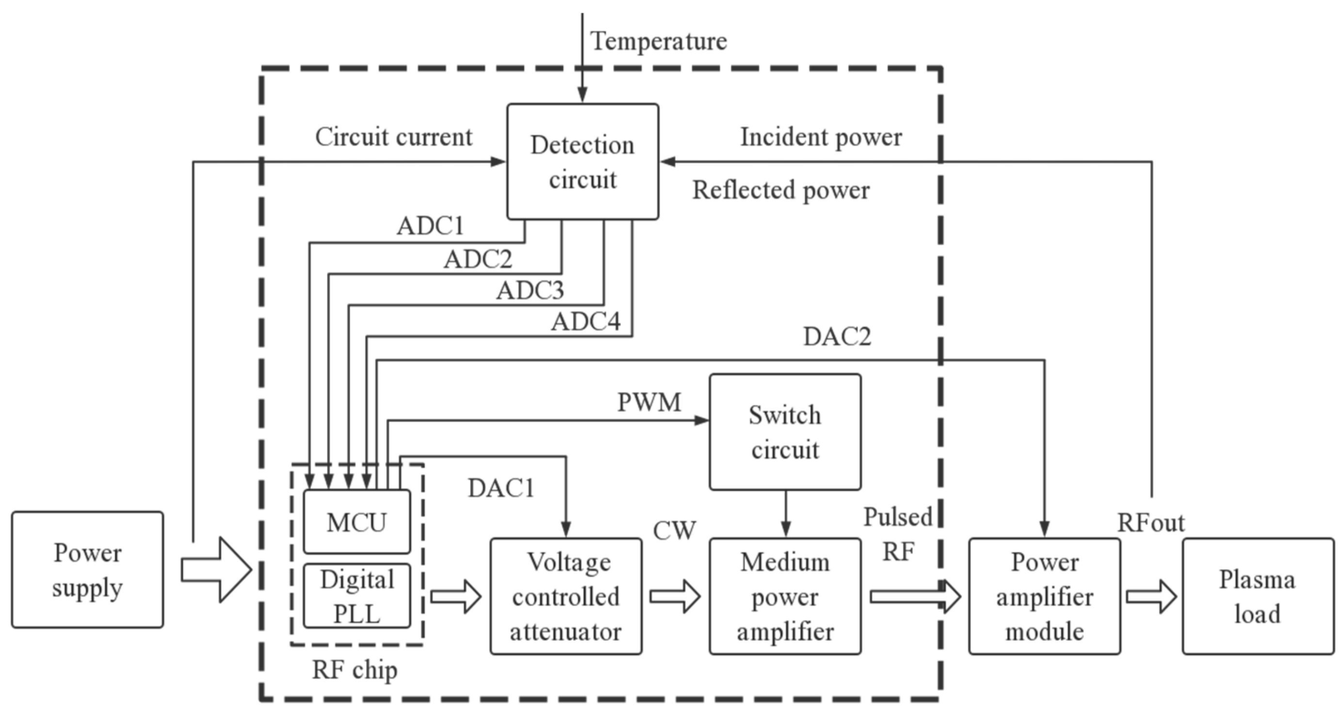
The structure of the plasma lighting system is shown in Figure 1. The microwave signal within a band of 430–460 MHz is generated by the digital PLL and finally output to the plasma load through a voltage-controlled attenuation network and multi-stage power amplifiers. The attenuator is used to improve the resolution of the power adjustment. With the signal conversion of the peripheral detection circuits, the MCU utilizes analog-to-digital conversion channels (ADC) to monitor various parameters continuously and control the startup of the plasma lamp.

2.2. The RF Source Circuit

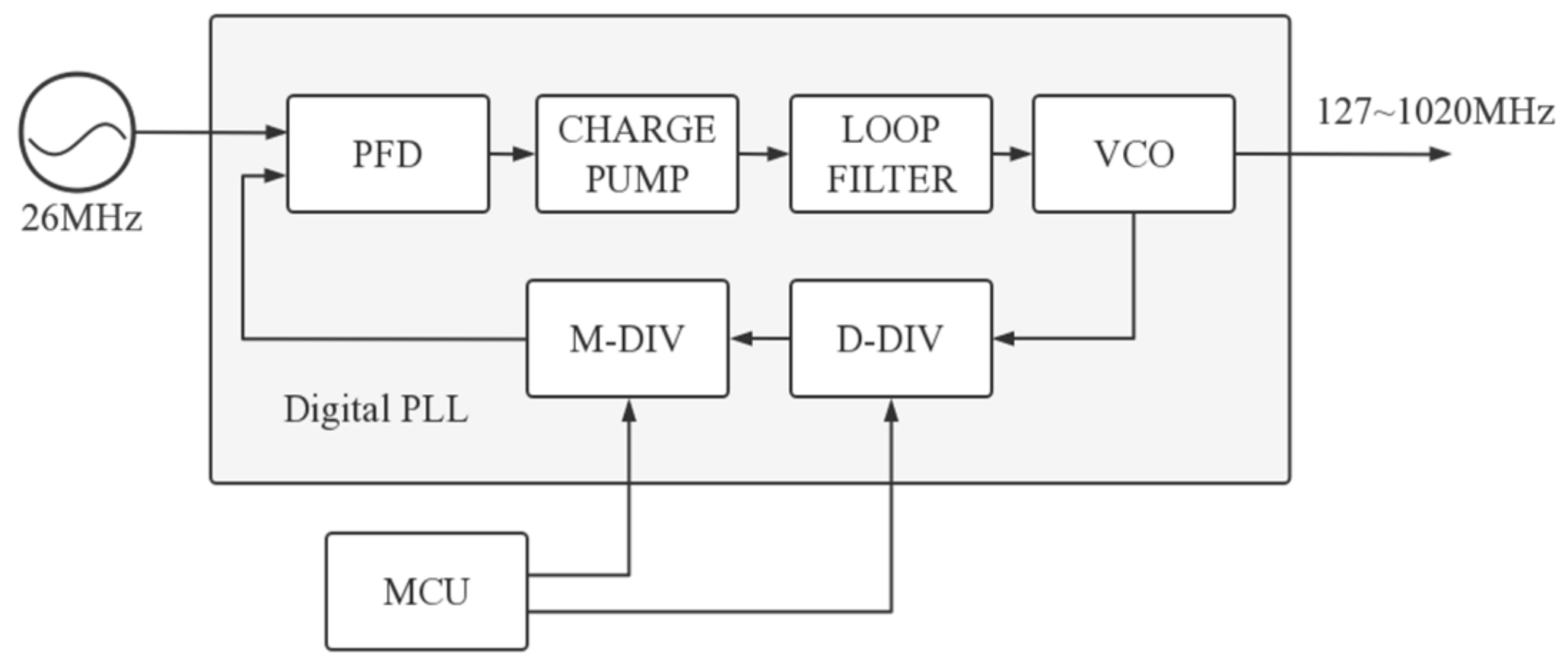
Generally, a fractional-N PLL provides the high-frequency carrier for communication and is used as the RF source for plasma lamps in this design. An integration chip named CMT2380F32 from HOPERF Corporation is adopted as the signal generating and control unit for compact structure. Besides a fractional-N PLL, it also includes an ARM Cortex-M0 MCU and an RF transmitter. As shown in Figure 2, the fractional-N PLL consists of a PFD, a charge pump, a loop filter, a VCO, a dual-modulus prescaler (D-DIV), and a 20-bit fractional frequency division modulator (M-DIV). The reference signal is from an outside crystal oscillator, and the feedback signal is formed by dividing the frequency of the VCO with the M-DIV and D-DIV. The error signal between the reference signal and the feedback signal is outputted by the PFD, integrated by the charge pump, and filtered by the low pass loop filter. The RF output signal of the VCO is locked at the desired frequency by the error signal of the PFD when the frequency of the reference signal and the feedback signal are the same. Under the 26 MHz input reference frequency, the output signal of the PLL can achieve a resolution of 25.8 Hz over a frequency range of 127–1020 MHz.
When the solid-state RF driver is used for the plasma lighting system, the sweeping frequency signal is very useful for fast startup. The change in the frequency can be realized by modifying the frequency division ratio N, which is calculated by:
N = f VCO × C DIV f REF = D + M 2 20
where fREF is the reference frequency, fVCO is the output frequency and CDIV is the frequency division coefficient. D and M 2 20 is the integer part and the fractional part of N, respectively. CDIV = 4 is chosen in this design. For example, if the desired output frequency fVCO is 450 MHz, then
N = 450 MHz × 4 26 MHz = 69.23076923
D = 69
M = 0.23076923 × 2 20 = 241979
The frequency of the output signal can be adjusted to 450 MHz by writing D and M, respectively, into the registers controlling the D-DIV and M-DIV.
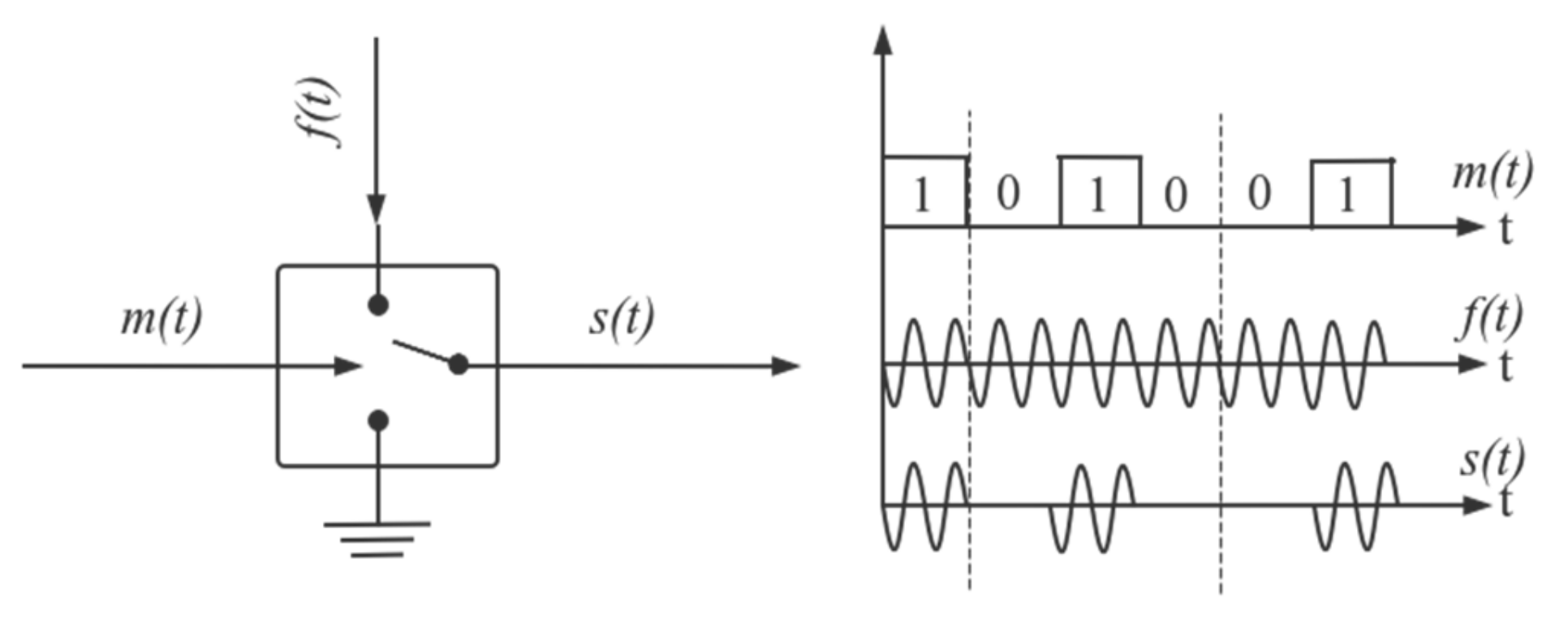
The RF transmitter has two modulation modes, On-Off Keying (OOK) [17] and Gauss Frequency Shift Keying (GFSK). Additionally, OOK is a special case of Amplitude Shift Keying (ASK). As shown in Figure 3, the base-band signal m(t) adopts a unipolar NRZ code that “1” is a high level and “0” is a zero level. As a switch signal, m(t) controls the continuity of the high-frequency carrier f(t), and the output signal s(t),
s ( t ) = m ( t ) × f ( t )
when m ( t ) = 1 , we obtain
s ( t ) = f ( t )
During the startup process, plasma light sources usually work in the continuous wave mode to absorb enough energy and achieve final arc discharge as soon as possible. Using the modulation principle of the digital signal, the relevant registers in the PLL are configured to force the transmitter work in the OOK and DIRECT mode, and DIRECT means that data are sent directly without encapsulation. As shown in Figure 4, when the DATA pin is kept at a high level, the PA pin can output a continuous wave with the desired frequency. The input frequency for the plasma load circuit could be changed by continuously modifying the frequency division ratio N of the PLL.
The RF transmitter has two states, STBY and TX. During frequency hopping, it is necessary to enter the STBY state to modify the RF frequency registers, and then switch back to the TX state to output this signal. Unfortunately, the PLL stops working at the STBY state, but the state is necessary for registers to be accessed and modified, causing a cut-off time with no RF power output. In addition, there is also a period of 370 µs for PLL calibration and stabilization from STBY to TX. Therefore, one frequency hopping must go through the state transition of TX-STBY-TX, which can be shortened to 0.8 ms at least. This phenomenon may cause the plasma light source to extinguish due to the lack of the continuous injection of RF energy.
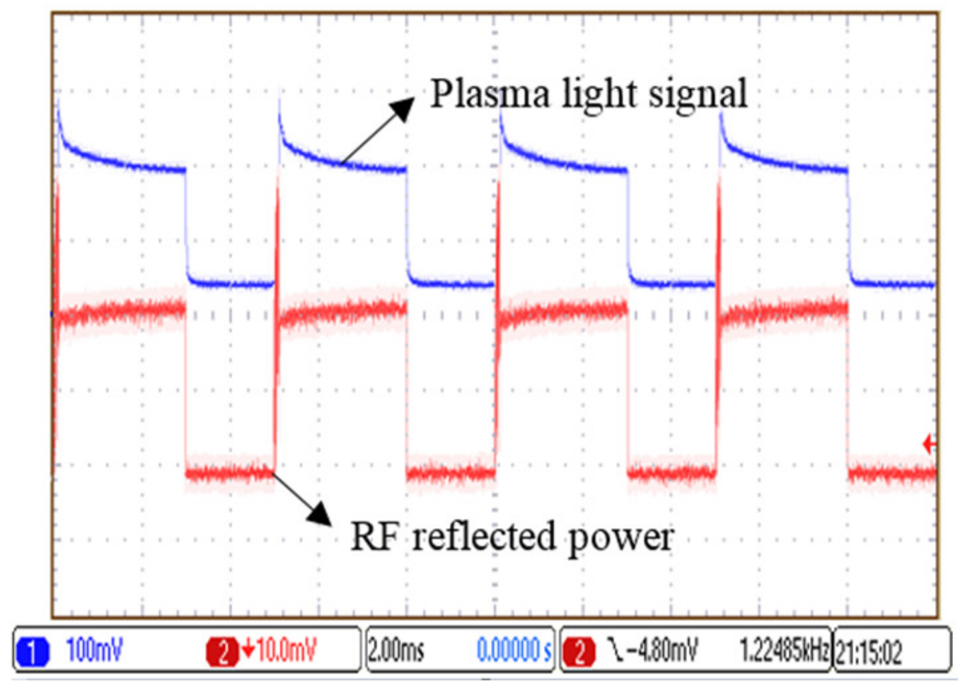
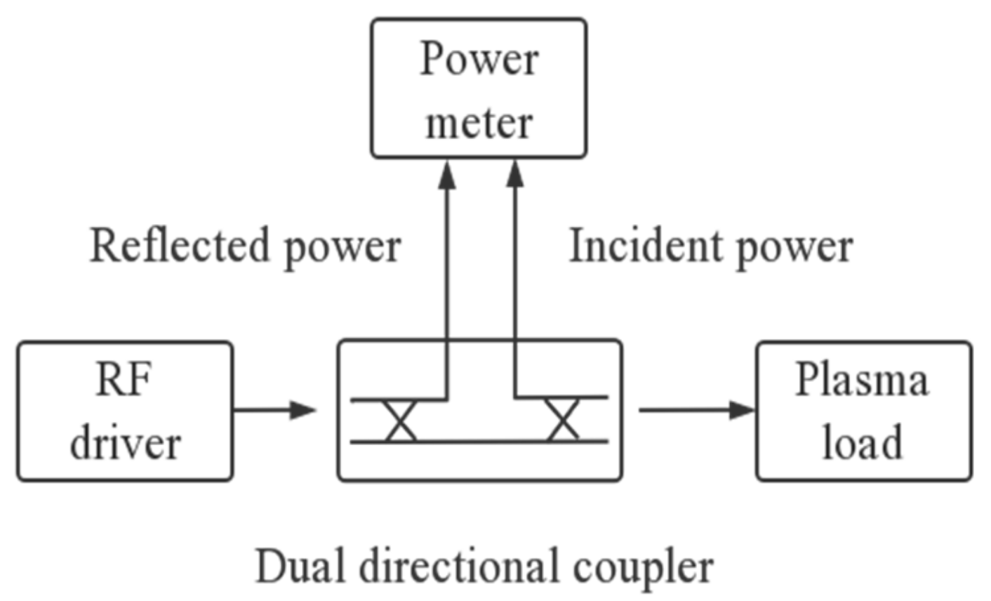
In order to study the effect on plasma, the maximum cut-off times of maintaining the plasma after a gas breakdown are tested in the glow discharge stage. The reflected power and the light signal measured under the condition indicate that the peak incident power is 30 W, the pulse period is 5 ms, and the duty cycle is 60%. As shown in Figure 5, it is found in experiments that the light signal emitted by plasma will disappear as soon as the energy injection stops. However, when the next energy injection pulse comes again after the cut-off time, the plasma will light up immediately. The allowable interval of the cutoff time is up to 2.9 ms at the peak power of 30 W and will lengthen with the increase in the incident power. The 0.8 ms of time required for one frequency hopping is shorter than the maximum cut-off time, so the startup of the plasma light source will not be affected.
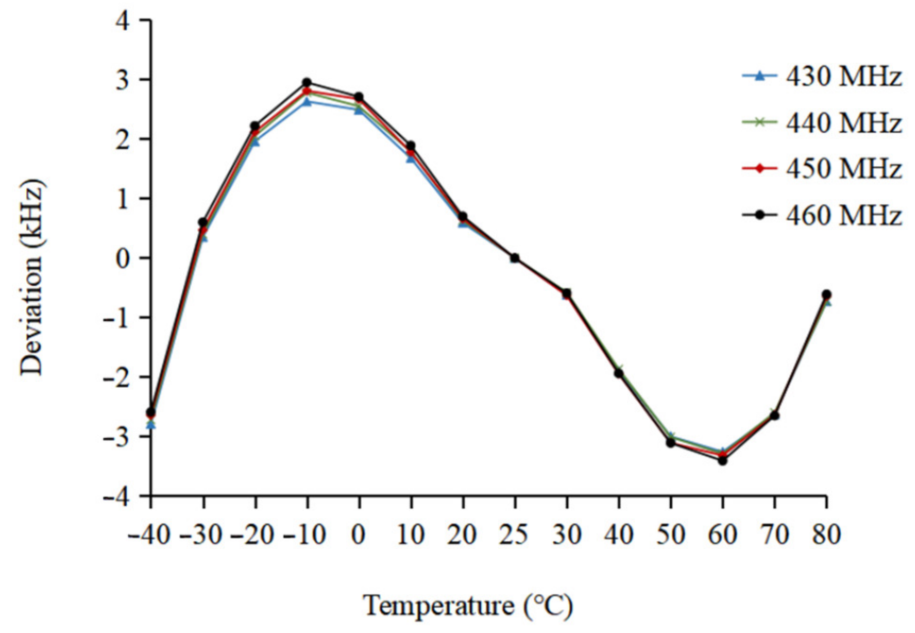
The stability of the output frequency is important for plasma lamp startup in different environments. One of the main reasons for PLL temperature drift is that the reference oscillation frequency of the crystal fluctuates under different temperatures [18]. The working temperature of the plasma lamp is −40–85 °C, where the temperature coefficient of frequency (TCF) of the RF crystal used is 10 ppm. The temperature drift ∆f1 for the 26 MHz oscillation frequency fREF could be obtained according to Formula (7),
Δ f 1 = TCF × f REF = 10   ppm × 26   MHz   = 260   Hz
Δ f 2 = Δ f 1 × f MAX f REF = 260   Hz × 460   MHz 26   MHz = 4.6   kHz
Therefore, the theoretical temperature drift ∆f2 for the highest working frequency fMAX of the RF source is 4.6 kHz, calculated by the Formula (8).

2.3. The Control Circuit

The RF control module is an important part of the RF driver for plasma lighting systems, providing a signal source with adjustable power and frequency to control the power amplifier, excite the gas discharge and complete the startup of the plasma light.
The MCU collects the consumption DC of whole circuits, the temperature, incident power, and reflected power of the plasma load, respectively, through four analog-to-digital conversion channels (ADC). According to these measured parameters, MCU controls the output RF power by adjusting the attenuation intensity of the voltage-controlled attenuator and the working state of the power amplifier module, respectively, through two digital-to-analog conversion channels (DAC). In addition, pulse modulation for the RF signal is realized through another PWM channel to improve the system luminous efficacy of the plasma lamp.
A four-PIN diode π attenuation network is used as the attenuator. The resistance value of the PIN diode could be adjusted continuously under the control of the current and shows linear resistance to microwave signals, which can achieve better matching and flatter attenuation in a wide range of frequencies [19]. The voltage of the attenuator is controlled by the MCU to prevent sparking between the bulb electrodes due to current overshoot and insufficient energy injection due to low current. Hence, damage to the bulb or plasma extinguisher could be avoided. Besides that, it is also necessary to stabilize the circuit current for the plasma light startup process and adjust the light intensity during the steady operation phase through the attenuator.
A high-frequency triode is used as the medium power amplifier and the maximum output power of 21 dBm is obtained. It has been reported that the conversion efficiency from electric to light energy could be improved by using a modulated RF pulse signal [
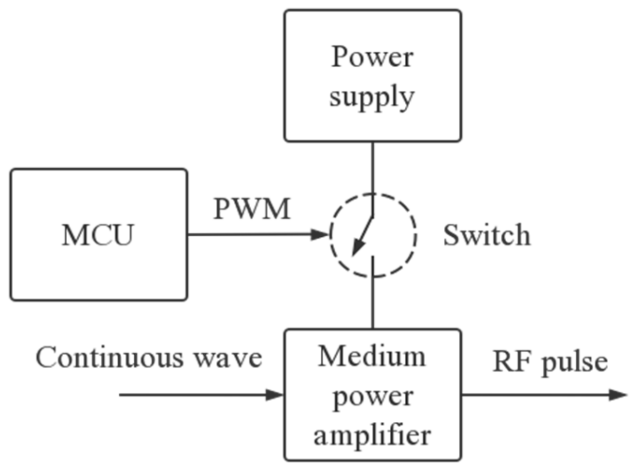
20]. The data rate of the transmitter is too low for pulse modulation with a frequency of 87 kHz and a duty cycle of 90%. Therefore, another way for pulse modulation is needed. As shown in Figure 6, a PWM signal output by the MCU is used as the switch signal to control the switch circuit, then the following DC power supply of the medium amplifier will be modulated, and an RF pulse signal could be obtained. The pulse period and the duty cycle of the RF pulse signal are determined by the MCU.
In the initial stage of the startup, the plasma load is mismatched, and the reflection coefficient is very high, so high incident power is required for the gas breakdown. With the warm-up of the plasma, the reflection coefficient continues to decrease and then enters a stable arc discharge stage when the reflection is low enough to indicate the completion of the startup. In the final stage, the controlling method aims to improve the conversion efficiency of the amplifier. The quiescent operating point of the power amplifier is adjusted by the gate voltage through DAC so that the working type of the amplifier changes into class C from class AB in the early stage [21].

2.4. Design of Control Flow

During the startup of the plasma light source, the dielectric material inside the bulb changes into plasma from a low-pressure vacuum. Additionally, the relative permittivity εp of the plasma is determined by the following formulas [22]:
ε p = 1 ω p 2 ω 2 + ν 2 i ω p 2 ν ω ( ω 2 + ν 2 )
ω p = n e e 2 ε 0 m e
where ωp is the oscillation frequency of the plasma, ν is the collision frequency of electrons with other particles, ne is the electron density in the plasma, and e and me are the charge and the mass of a single electron. With the increase in the electron density in the warm-up process, it can be predicted that the input impedance of the resonator and the optimal frequency for RF energy absorption are constantly moving under the mutual influences of these parameters. In order to analyze the general trend of impedance change and find a control method for quick startup, it is assumed that ne is 1.8 × 10¹⁹/m3 and ν is 5.0 × 10¹¹ Hz after the gas is instantly broken down. According to Formulas (9) and (10), εp = 0.77−41.46 i is obtained. These material values are used in a high-frequency structural model of the resonator and the bulb to carry out electromagnetic simulation. Then, both the return losses S11 of the resonator before and after the gas breakdown in the bulb are calculated over different frequencies. As shown in Figure 7, the curve shifts obviously to the lower frequency once the plasma forms. Note that the curve of the return loss will change continuously with the injection time of microwave energy.
Therefore, a method of changing the driving frequency is used in this design for the fast absorption of the RF energy. The startup of the plasma light source is performed in three stages: ignition, preheating, and operation. In these stages, the status of the plasma light is evaluated according to the various measured parameters described in the control circuit section. The output power of the RF amplifier and the input driving frequency are controlled for quick RF coupling so that the plasma absorbs enough energy, transitions to the final arc discharge from glow discharge, and achieves complete impedance matching as soon as possible.
In the ignition stage, a PWM signal with a full duty cycle is used to the switch circuit so that the RF driver outputs a continuous wave. As shown in Figure 7, the input frequency is controlled to sweep downward rapidly from the point F0, which is above the frequency F1 with a minimum return loss before breakdown. After arriving at the frequency F1, the DC of the circuit at this point is acquired from the ADC. Then, the driving signal continues down to the point F2, and the DC at this point is also acquired. Whether the plasma forms can be determined by comparing the values of the two currents. If the current at F2 is larger than that at F1, it means that the curve in Figure 7 has moved to the lower frequency and the gas filled in the bulb has been successfully broken down into plasma. Then, the startup process enters the preheating stage, and the plasma begins to glow discharge. Otherwise, the ignition is failed, and the startup process should be restarted. Due to the high reflected power in the ignition stage, the power amplifier needs to work at class AB with full power output to ensure successful breakdown.
In the preheating stage, the plasma warms up and transitions to the high-intensity arc discharge gradually. The control method at this stage is shown in Figure 8. The frequency continues to sweep down until it crosses over the new frequency point with the lowest return loss established by the plasma. Then, the load mismatch of the RF driver will aggravate, and the consumed DC will decrease rapidly. When the current cannot be maintained within the rated working range by controlling the attenuator, the frequency should stop downward immediately and begin to move upward in order to prevent the plasma from extinguishing. The frequency is shifted up for maximum incident power at a safe rated current, and then the incident driving signal is kept waiting at this status. With the microwave heating, the plasma density increases, and the load matching of the RF driver improves. When the reflection coefficient measured by the ADC drops to a value lower than 0.45, the frequency starts to move up and track the frequency with the maximum incident power, and the illumination of the plasma lamp will gradually heighten. If a reflected power detected is low enough and below 1 W, it means that the preheating stage has been completed, and the plasma has converted into an arc discharge stage from the glow discharge. Then, the plasma lamp enters the steady operation stage.
During the operation of the arc discharge stage, the impedance matching between the RF driver and the resonator is well and the reflected power is small enough. The amplifier is able to output sufficient RF power under the matched load to maintain the plasma discharge. To improve the drain efficiency of the amplifier, the gate voltage of the power transistor is reduced to zero biased, making the power amplifier in the RF driver work in the class C mode.
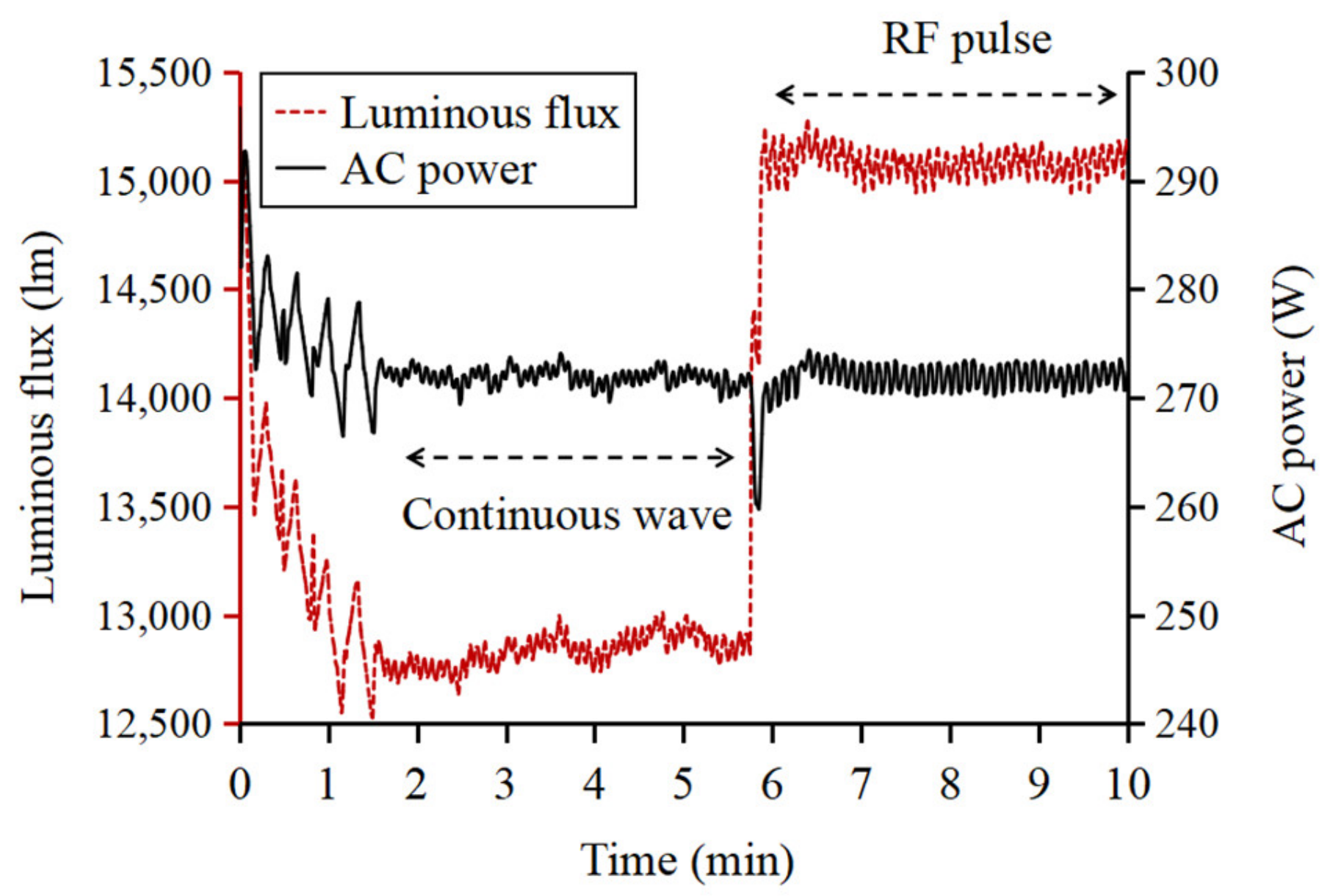
Affected by temperature, the frequency with the minimum reflected power will sway slightly, so it is necessary to adjust the driving frequency up and down and follow the optimal reflection. After several minutes, the pulse modulation is turned on, and the RF driver outputs the amplified power pulses with several hundred watts so as to improve the system luminous efficacy. Moreover, the temperature of the RF driver and reflection coefficient are monitored at the same time for the reliability of the system. A high temperature will reduce the lifetime of the RF driver, and the output of the RF energy should be stopped to prevent the amplifier from being damaged. A high reflection coefficient means the failure of the startup and the startup process of the plasma lamp should restart after cooling down.

3. Test and Validation

According to the above scheme, the RF control module, including the RF signal source and the control circuits, is designed and made on a four-layer PCB. For validation of the control method, the microwave and temperature performance of the RF source were tested firstly, and then the RF control module was used to drive a high-power amplifier module, and an entire RF driver was fabricated. Two-stage amplifiers are included in the power amplifier module, and an LDMOS transistor named BLC10M6XS200 from AMPLEON is selected as the final stage with a maximum output power of 200 W in the working bandwidth of the plasma lamp. The output of the RF driver is connected to an emitter composed of a rectangular ceramic resonant cavity and a bulb by a coaxial line, and a plasma lighting system was built, as shown in Figure 9.

3.1. Frequency, Power, and Temperature Drift of the RF Source

In order to test the performance of the RF source, the output port of the RF control module is connected to an ADVANTEST U3751 spectrum analyzer through a coaxial wire and a 20 dB attenuator. The insertion loss of the coaxial wire is −3 dB, the DC voltage of the internal attenuator is 2 V, and the signal frequency controlled by the MCU sweeps down from 470 MHz with 100 kHz as one frequency hopping interval. The measured results of power and frequency are shown in Figure 10. It can be obtained that the output power is 21 dBm and the power flatness is 0.23 dB over the range of 430–460 MHz. Therefore, the output power of the RF source is relatively stable under different frequencies.
For evaluating the frequency drift of the RF signal at actual operating temperatures, the RF control module is placed and tested in a thermostat. The temperature of the thermostat is adjusted in steps from −40 °C to 80 °C with an interval of 10 °C, and it stays for 20 min at every temperature before recording the data so as to ensure the control module is measured at a steady temperature. Taking into account that the theoretical temperature drift is in the order of kHz, a frequency meter is used to measure the output frequency of the RF source. Compared with the frequencies at the room temperature of 25 °C, the frequency deviations can be obtained under different temperatures.
As shown in Figure 11, the maximum frequency deviation is 3.3 kHz in the full range of the working temperature for different driving frequencies, which is close to the theoretical temperature drift.

3.2. Startup of the Plasma Light Source

To verify the correctness of the control flow, the emitter of the plasma lamp is placed at the top of a rotating integrating sphere so that the light from the bulb could radiate into it. A HAAS-2000 high-precision fast photoelectric test system from the EVERFINE Corporation is adopted to measure the consumed AC electric power and the optical parameters such as luminous flux, correlated color temperature (CCT), and color rendering index (CRI).
It takes 79 s for the RF driver to successfully start the plasma lamp and achieve stable arc discharge operation. As shown in Figure 12, the output luminous is 12,800 lm when the continuous wave is used for driving the plasma lamp. After the RF pulse signal is used with the modulated frequency of 87 kHz and the duty cycle of 90%, the luminous flux increases to 15,100 lm under the same electric power of 272 W, meaning that the RF energy conversion efficiency from electricity to light or the system luminous efficacy has been improved by 18%. The light emitted by plasma has a CRI of 91.4 and a CCT of 5003 K. Additionally, a continuous full spectrum could be obtained from an optical spectrum analyzer in the test system.
A dual directional coupler is added between the RF driver and the emitter to further evaluate the coupling between the RF driver and the plasma load, as shown in Figure 13. The incident power and the reflected power are measured accurately by sampling the signals from the directional coupler using an external power meter. When the plasma lamp enters the arc discharge stage with the continuous wave operation, the incident power is 171 W, the reflected power is stable at 418 mW, and the return loss is −26 dB. The measured result means that the RF driver and the plasma load achieve good coupling with 99.76% of the microwave power transferred into the emitter for exciting the plasma lighting. Table 1 shows the comparison results between the VCO method and the proposed fractional-N PLL method for the RF control module. The VCO method is realized by using an MCU with a 10-bit PWM signal to control the frequency, and the data are obtained from the previous experiments we have carried out. Compared with the VCO method, it can be seen that the frequency stability under the different temperatures and the resolution have been greatly improved by using the fractional-N PLL method. Furthermore, the high precision of the frequency, implying that the output frequency is just what we need, reduces the calibration work for outputting the accurate frequency of the RF source.

4. Conclusions

A startup control method for plasma lamps by using an integrated fractional-N PLL as the RF signal source is proposed. There are three improvements in this design and control method. First, the RF source using the fractional-N PLL is less affected by the environment temperature, which also ensures the accuracy of the driving frequencies for starting the plasma lamp. Second, the driving frequency is changed in time according to the measured electrical parameters during the start-up process, so that rapid coupling between the RF driver and the plasma load is achieved and the plasma lamps are started up quickly. Finally, pulse modulation is used to improve the system’s luminous efficacy.
The plasma lighting system has been built up and tested by using the designed RF control module. The results indicate that the performance of the frequency and power of the RF source is stable, and the frequency drift is as low as 3.3 kHz over the temperature of −40–80 °C, ensuring the accuracy of the driving frequency during startup. The designed detection circuits and the control method of changing frequency can meet the requirement of plasma lamp startup. The plasma lamp could complete the start and enter the stable arc operation in 79 s. Good coupling between the RF driver and the emitter could be obtained, with 99.76% of the microwave energy transferred into the emitter of the plasma lamp. Compared with RF continuous wave driving, the luminous flux powered by the RF pulse modulation improves by 18% under the same electric power.
This control method and the designed RF control module can be used in various plasma lighting lamps such as industrial production, underground mines, vegetable cultivation, and so on. It has a broad application prospect.

Author Contributions

Methodology, H.J.; software, M.X.; validation, M.X., H.J. and W.H.; writing—original draft preparation, M.X.; writing—review and editing, H.J.; project administration, J.S. All authors have read and agreed to the published version of the manuscript.

Funding

This research was funded by the National Natural Science Foundation of China, grant number 11675212.

Conflicts of Interest

The authors declare no conflict of interest.

References

  1. Godyak, V.A. Bright idea, radio-frequency light sources. IEEE Ind. Appl. Mag. 2002, 8, 42–49. [Google Scholar] [CrossRef]
  2. Zissis, G.; Damelincourt, J.J. Electrical discharge light sources: A challenge for the future. High Temp. Mater. Processes 2002, 6, 397–409. [Google Scholar] [CrossRef]
  3. Lister, G.G.; Waymouth, J.F. Encyclopedia of Physical Science and Technology, 3rd ed.; Academic Press: Salt Lake City, UT, USA, 2003; pp. 557–595. [Google Scholar]
  4. Gilliard, R.R.; Devincentis, M.; Hafidi, A.; O’Harel, D.; Hollingsworth, G. Longitudinally mounted light emitting plasma in a dielectric resonator. J. Phys. D Appl. Phys. 2011, 22, 224008. [Google Scholar] [CrossRef]
  5. Yuan, Z.C.; Shi, J.M. Theoretical and numerical study of interaction between high power microwave and plasma. Acta Phys. Sin. 2014, 63, 255–264. [Google Scholar]
  6. Kim, D.H. Electromagnetic and Chromatic Analyses of Plasma in Transient State. In Proceedings of the Pulsed Power Conference (PPC), Francisco, CA, USA, 16–21 June 2013. [Google Scholar]
  7. Holtrup, S.; Sadeghfam, A.; Heuermann, H.; Awakowicz, P. Characterization and optimization technique for microwave-driven high-Intensity discharge lamps using hot-parameters. IEEE Trans. Microw. Theory Tech. 2014, 62, 2471–2480. [Google Scholar] [CrossRef]
  8. Koulakis, J.P.; Thornton, A.L.F.; Putterman, S. Magnetron coupling to sulfur plasma bulb. IEEE Trans. Plasma Sci. 2017, 45, 2940–2944. [Google Scholar] [CrossRef]
  9. Nett, A.S. Light Source Powered by Microwaves. Patent CN102439690A, 2 May 2012. [Google Scholar]
  10. Al-Shamma’a, A.I.; Pandithas, I.; Lucas, J. Low Pressure Microwave Plasma UV Lamp for Water Purification and Ozone Production. In Proceedings of the PPPS-2001 Pulsed Power Plasma Science 2001, Las Vegas, NV, USA, 17–22 June 2001. [Google Scholar]
  11. Jia, H.; Shan, J.F.; Lui, F.K.; Huan, W.D. Design of high-efficiency solid-state power source for RF plasma light source. Fusion Plasma Phys. 2021, 41, 91–96. [Google Scholar]
  12. Hollingsworth, G.; Devincentis, M.; Mudunuri, S. Low Frequency Electrodeless Plasma Lamp. Patent CN102239750B, 23 September 2015. [Google Scholar]
  13. Carlo, S. Understanding phase noise in LC VCOs: A key problem in RF integrated circuits. IEEE Solid State Circuits Mag. 2016, 4, 81–91. [Google Scholar]
  14. Lu, H. Research on RF Source of Microwave Plasma Lamp. Master’s Thesis, University of Electronic Science and Technology of China, Chengdu, China, 2014. [Google Scholar]
  15. Singhal, A.; Madhu, C.; Kumar, V. Designs of All Digital Phase Locked Loop. In Proceedings of the 2014 Recent Advances in Engineering and Computational Sciences (RAECS), Chandigarh, India, 6–8 March 2014. [Google Scholar]
  16. Lai, W.-C.; Huang, J.-F.; Wen, C.-L. FPGA Implementation of A MASH 1-1-1 Delta-Sigma Modulator Infractional-N Phase Locked Loop for Fuzzy Control Application. In Proceedings of the 2014 11th International Conference on Fuzzy Systems and Knowledge Discovery (FSKD), Xiamen, China, 19–21 August 2014. [Google Scholar]
  17. Schwartz, M. History of communications. IEEE Commun. Mag. 2008, 46, 42. [Google Scholar] [CrossRef]
  18. Wen, J.; Sun, X.-M.; Zhan, C.; Zhong, Y.-H.; Wang, J. An Analysis of Frequency-Temperature Relations of At-Cut Quartz Crystal Resonators by Finite Element Method with Comsol. In Proceedings of the 2019 13th Symposium on Piezoelectrcity, Acoustic Waves and Device Applications (SPAWDA), Harbin, China, 11–14 January 2019. [Google Scholar]
  19. Miao, X.F.; Wang, X.H. Design of RF Attenuator Based on PIN Diode. In Proceedings of the International Conference on Advanced Material Science and Environmental Engineering (AMSEE), Chiangmai, Thailand, 26–27 June 2016. [Google Scholar]
  20. Kang, W.; Ku, H. An Efficient Dimming Scheme for a Plasma Lighting System Using Solid-state Power Amplifier. In Proceedings of the Progress in Electromagnetics Research Symposium-Spring (PIERS), St. Petersburg, Russia, 22–25 May 2017. [Google Scholar]
  21. Herceg, E.; Urbanec, T. Comparison of Class C and High Efficiency Class E Amplifiers at 435 MHz. In Proceedings of the 2019 29th International Conference Radioelektronika (RADIOELEKTRONIKA), Pardubice, Czech Republic, 16–18 April 2019. [Google Scholar]
  22. Kando, M.; Fukaya, T.; Ohishi, Y. Application of an antenna excited high pressure microwave discharge to compact discharge lamps. J. Phys. D Appl. Phys. 2008, 41, 144026. [Google Scholar] [CrossRef]
Figure 1. Structure of hardware circuit of the plasma lighting system.
Electronics 11 02576 g001
Figure 2. Block diagram of fractional-N PLL.
Electronics 11 02576 g002
Figure 3. Principle of OOK.
Electronics 11 02576 g003
Figure 4. Transmitter configuration of fractional-N PLL as RF source.
Electronics 11 02576 g004
Figure 5. Variation relationship between RF reflected power and plasma light signal in glow discharge stage.
Electronics 11 02576 g005
Figure 6. Schematic diagram of pulse modulation for RF signals.
Electronics 11 02576 g006
Figure 7. The S11 and input frequency curves of the resonator before and after gas breakdown. F0 is the starting sweep frequency. F1 is the frequency with minimum return loss before breakdown. F2 is any frequency between F1 and the frequency with minimum return loss after breakdown.
Electronics 11 02576 g007
Figure 8. Control flow chart of the preheating stage.
Electronics 11 02576 g008
Figure 9. The microwave plasma light source system.
Electronics 11 02576 g009
Figure 10. Output power for different frequencies within the working bandwidth of the plasma lamp.
Electronics 11 02576 g010
Figure 11. The temperature drifts under different temperatures.
Electronics 11 02576 g011
Figure 12. Changes in luminous flux and electric power during the startup process.
Electronics 11 02576 g012
Figure 13. RF coupling test system of the plasma lamp.
Electronics 11 02576 g013
Table 1. Comparison of the performance between VCO method and fractional-N PLL method.
MethodStartup
Time (s)
Temperature
Drift (kHz)
Frequency
Resolution (Hz)
Frequency
Precision (%)
Coupling
Efficiency (%)
VCO92400080,000±1.198.27
This work793.325.8±0.000799.76
Publisher’s Note: MDPI stays neutral with regard to jurisdictional claims in published maps and institutional affiliations.

