Abstract
The pill-box window is one of the important components of microwave vacuum electronic devices (VEDs), and research into it is of great significance. As the operating frequency increases, the problems associated with the reduction in the structure size include the reduction of the brazing plane and the reduction in the tolerance of the pill-box window. These problems will cause traditional pill-box windows to be unsuitable in high-frequency bands, especially in terahertz and sub-terahertz regions. The most influential factor is the length of the circular waveguide in the box window. The welding plane of the over-size pill-box window is the annular bottom surface on both sides of the dielectric sheet, which is larger than the circular waveguide, and the operating frequency does not directly affect the area of the brazing surface. Choosing a suitable diameter for the dielectric sheet can effectively increase the tolerance to the length of the pill-box window circular waveguide. Therefore, an over-size pill-box window would be a practicable approach to improve the performance compared to the traditional pillow-box in high-frequency bands. This paper describes, in detail, the theoretical design, simulation optimization and experimental process of this improved pill-box window. An over-size pill-box window suitable for G band VEDs was successfully developed. The experimental result in the 215–225 GHz band is that the maximum transmission loss is −1 dB, and the overall transmission loss is close to −0.5 dB. The overall reflection is less than −11 dB.
1. Introduction
In Recent decades, with the rapid development of terahertz science and technology, the lack of terahertz radiation sources has become, have limiting the research into and applications of the terahertz wave. Vacuum electronic devices (VEDs) (e.g., TWT, klystron, BWO, Gyrotron), which could transfer energies from electrons to electromagnetic waves in vacuum tubes, are the most powerful radiation sources in the low-frequency terahertz region and sub-terahertz region. The IAP-RAS (Institute of Applied Electronics-RAS) reported 10 kW, 1 THz gyrotron, CAEP (China Academy of Engineering Physics) reported 3.1 W, 336.96 GHz TWT, and CPI (Communications & Power Industries) reported 10 W, 264 GHz EIO/EIK (Extended Interaction Klystrons/Oscillatiors). The vacuum window is an important component of the vacuum electronic device [1,2,3]. It is used to maintain the high-vacuum condition while in the tubes, while inputting or outputting electromagnetic waves from or into the tubes.
The pill-box window is a widely used configuration in VEDs design [4,5,6,7], with the advantages of bandwidth, easy brazing, and high power capacity. Figure 1a shows the standard structure of a traditional pill-box window. It consists of a standard waveguide with input and output ports, a circular waveguide with a diameter equal to the diagonal of the standard waveguide, and a dielectric sheet brazed into the circular waveguide. The traditional pill-box window has a wide range of applications. However, the size of the traditional pill-box window is directly proportional to the operating wavelength. As the working frequency increases, the overall size of the pill-box window is reduced, and some problems arise in the realization of the traditional pill-box windows a result. The brazing surface of the traditional pill-box window is the cylindrical side surface of the dielectric sheet. The reduction in the size of the pill-box window will cause the reduction in the brazing surface, decreasing the air tightness and experimental tolerances. The higher the working frequency band of the pill-box window, the more difficult it is to process. The parameter that is most prone to experimental errors, and has the greatest impact on the experimental results, is the length of the circular waveguide of the pill-box window (L1) [5,6]. In the W-band, an asymmetric structure is used, and the influence of processing errors on the test results of the box window can be reduced through multiple transmission tests [6]. However, in the G-band, the asymmetric structure cannot solve the problem of a too-small welding surface, and the air tightness of the pill-box window cannot be guaranteed. The improved over-sized pill-box window shown in Figure 1b can effectively solve the above problems. The brazing surface of the improved pill-box window is the annular bottom surface of the dielectric sheet, which is larger than the circular waveguide. The brazing area will not change with the increase in working frequency. During the design process, we found that the tolerances in dielectric sheets with different diameters to pill-box windows are different. Choosing a suitable diameter for the dielectric sheet can effectively increase the tolerance of the pill-box window, thereby reducing the difficulty of achieving high-frequency pill-box windows.
Figure 1.
Structure of the (a) traditional pillbox window and (b) improved pillbox window.
In this paper, an over-size pill-box window for sub-terahertz VEDs at G band (215–225 GHz) is investigated, as outlined in the above structure. In the second part of this article, the theoretical design and simulation optimization of the improved box window are described in detail. The third part realized the G-band pill-box window according to the design and processing. The fourth part summarizes this article.
2. Model Design and Simulation
The pill-box window design begins with choosing the right material as the medium window sheet. Materials such as quartz, ceramics, diamond and sapphire are often used for the dielectric sheets of pill-box windows. Compared with other dielectric materials, sapphire has the advantages of high mechanical strength, low loss tangent, and mature metallization technology. Sapphire is an anisotropic material, but the perturbation of its dielectric constant does not affect the transmission of the transverse electric (TE) mode in the over-size pill-box window [7]. Therefore, the dielectric material selected in this design is sapphire, and its dielectric constant is 9.4.
There are many published theoretical calculation methods, such as the impedance-matching approach [3,5], the method of moments [8], and the equivalent circuit method [4,5,6,7,8,9]. In this paper, the equivalent circuit method, with a relatively simple calculation, is selected. In the equivalent circuit theory, the connection point between the waveguides and the waveguide of the pill-box window are equivalent to a two-port circuit element. The transmission modes of the rectangular waveguide and the circular waveguide in the pill-box window are TE10 mode and TE11 mode, and the equivalent circuit is shown in Figure 2.
Figure 2.
Equivalent circuit diagram of pill-box window.
In Figure 2, L is the length of the rectangular waveguide; β is the propagation constant of the rectangular waveguide; Z is the characteristic impedance of the rectangular waveguide; Bc is the equivalent susceptance of the connecting part of the rectangular waveguide and the circular waveguide; L1 is the length of the cylindrical waveguide; β1 is the propagation constant of the cylindrical waveguide; Z1 is the characteristic impedance of the cylindrical waveguide; L0 is the length of the sapphire cylinder; β0 is the propagation constant of sapphire dielectric waveguide; Z0 is the characteristic impedance of sapphire dielectric waveguide; a M is the transfer matrix of the connection part and each waveguide.
The multiplication of the transmission matrix of each the transition part and each waveguide of the pill-box window is equal to the overall transmission matrix of the pill-box window. This can be written as
where the ‘’ in the formula means multiply, the ‘*’ in the formula represents the inverse matrix. The specific expression formula of each transfer matrix can be found in the literature [7]. Through the simplification of the transfer matrix and the relationship between the scattering matrix and the transfer matrix, the scattering matrix of the equivalent circuit can be obtained. The specific derivation process can be obtained from the literature [6,7]. By substituting the ideal transmission conditions: S12 = S21, S11 = S22 = 0 into the scattering matrix the equations for the structural parameters of the box window can be obtained as
According to the test conditions of the vector network analyzer (VNA) in our laboratory and the operating frequency of the pill-box window, the rectangular waveguide selected in this design is WR-5 (waveguide name of EIA standard). Equation (2) is an equation about f, L1, L0, R1, R0. When the frequency is determined to be 220 GHz, these four parameters have countless solutions. In order to obtain the ideal over-size pill-box window structure parameters, it is necessary to limit the values of the parameters before solving. The increase in the thickness of the sapphire sheet will increase the mechanical strength and power capacity of the pill-box window. However, the increase in thickness will reduce the matching degree of the pill-box window, that is, the bandwidth will become smaller. Therefore, the thickness of the sapphire sheet can be limited one-quarter waveguide wavelength to half the waveguide wavelength (). If the radius of the circular waveguide is too large, it is easy to produce higher-order modes. However, when the diameter of the circular waveguide is the diagonal length of the rectangular waveguide, the bandwidth of the box window is narrow. Therefore, the radius of the circular waveguide can be selected as . To simplify the theoretical calculation, the radius of the dielectric sheet is temporarily set as . When the length of the circular waveguide is less than the length of the dielectric sheet, the matching degree of the box window will be reduced, and the bandwidth will be reduced. In order to reduce the calculation time, the length of the circular waveguide should be controlled within one waveguide wavelength. The length of the circular waveguide is between the length of the dielectric sheet and a waveguide wavelength (). Substituting the solutions in Equation (2) that meet the value ranges of the four parameters into the scattering matrix of the window system, take the solutions with the largest bandwidth with a reflection less than −15 dB as the theoretical design parameters of the pill-box window, as shown in Table 1.

Table 1.
Structural size parameters of the pill-box windows.
The equivalent circuit theory is not an accurate theoretical calculation, and the designed structural parameters can only be used as an initial value. The specific size of the over-size pill-box window should be optimized by 3D electromagnetic simulation software (HFSS). In the simulation, the dielectric constant of sapphire is 9.4, and the dielectric loss tangent is 0.006. In the high-frequency pill-box window experiment process, the error capacity of the circular waveguide length (L1) is the biggest factor affecting the pill-box window test results. The optimized condition is to ensure that the transmission bandwidth of the pill-box window is 215–225 GHz, which maximizes the tolerance of L1. The specific optimization process is that the thickness of the sapphire and the radius of the circular waveguide remain unchanged, the radius of the different dielectric sheets are taken, and the transmission and reflection of different L1 values () at 220 GHz are scanned. This paper selected five different R0 values, and recorded the transmission loss and reflection corresponding to different L1 values at 220 GHz, under the condition that the maximum reflection in the 215–225 GHz band is less than −15 dB. The results are shown in the Figure 3. In the theoretical calculation of the traditional pill-box window, the size of the rectangular waveguide, and the radius of the circular waveguide and the dielectric sheet are determined by the operating frequency. Equation (2) is an equation about the length of the circular waveguide and the thickness of the dielectric sheet. The same theoretical calculation and simulation optimization are carried out in the traditional medicine box window. The results of the same simulation optimization of the traditional pill-box window are shown in Figure 3.
Figure 3.
(a) The transmission loss and (b) reflection simulation results of pill-box windows values with different L1.
From Figure 3a, the radii of the sapphire sheets of the over-size pill-box window are 1.75, 2, 2.5 and 3 mm, the change in the value of L1 has less influence on the transmission loss, and it is also less than the influence of traditional pill-box windows. When the radius of the dielectric sheets of the over-size pill-box window is larger (R0 = 3.75 mm), the change in the value of L1 has a greater impact on the transmission loss. In Figure 3b, it can be seen that the tolerance of L1 is different for sapphire sheets with different radii. Under the condition that the reflection of the pill-box window at 220 GHz is less than −30 dB and the maximum reflection in the 215–225 GHz frequency band is less than −15 dB, when the radius of the sapphire sheet of the over-size pill-box window is 1.75, 2, and 2.5 mm, the value change range of L1 is 0.08 mm. The range of L1 value of the traditional pill-box window under the same reflection condition is 0.03 mm. It can be seen that the radius of the sapphire sheet of the over-size pill-box window is set to an appropriate value, which can increase the tolerance of the structural parameters of the window system. The final radius of the sapphire in this paper is selected to be 2 mm because of the brazing and miniaturization of the pill-box window. The final structural parameters of the box window are shown in Table 1.
In a simulation template with PEC (Perfect Electric Conductor) as the background material, a pill-box window model, as shown in Figure 4, is established, and the rectangular waveguide openings at the upper and lower ends are set as the excitation source. The simulation result and theoretical calculation results of the transmission characteristics of the pill-box window are shown in Figure 5. It can be seen that the over-size pill-box window calculated by the equivalent circuit theory has a reflection of −42.5 dB at 220 GHz, but its bandwidth is relatively narrow. The optimized over-size pill-box window structure has good transmission performance in the simulation. The reflection in the 210–230 GHz frequency band is less than −30 dB, and the maximum transmission loss is −0.2 dB in the frequency band.
Figure 4.
The simulation structure of over-size pill-box window.
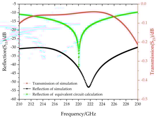
Figure 5.
Theoretical and simulated transmission characteristics.
In order to provide the corresponding error and accuracy of the experimental assembly and processing, it is necessary to perform error analysis on the structural parameters of the over-size pill-box window. It can be concluded from Figure 3 that the structural parameters L1 and R0 of the over-size pill-box window have a large tolerance. The error analysis is mainly on the radius of the circular waveguide (R1) and the thickness of the dielectric sheet (L0). By keeping the other structural dimensions of the pill-box window unchanged, the change in the value of R1, and the transmission loss and reflection of the pill-box window are shown in Figure 6. When the radius of the circular waveguide (R1) changes within 0.96–0.98 mm, the reflection of the pill-box window in the frequency band 215–225 GHz is less than −20 dB, and its transmission loss changes little. The same simulation error analysis is performed on the thickness of the dielectric sheet (L0), and the result is shown in Figure 7. When the variation range of L0 is 0.194–0.206 mm, the reflection parameters of the pill-box window are less than −20 dB in the 215–225 GHz band, and the transmission loss is less than −0.15 dB. It can be seen from the above that the tolerance difference in the two parameters R1 and L0 is ±0.01 mm and ±0.006 mm.
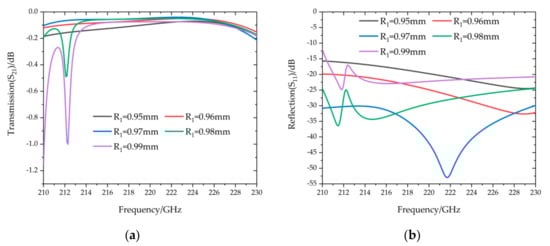
Figure 6.
(a) The transmission loss and (b) reflection of pill-box windows values with different R1.
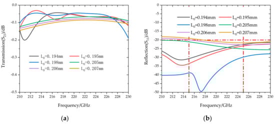
Figure 7.
(a) The transmission loss and (b) reflection of pill-box windows values with different L0.
3. Experiment Results
In the preliminary test of the over-size pill-box window, we found that the test size of the individual components was within the tolerance of the error analysis, but the test results after assembly and welding were not ideal. Because the over-size pill-box window being tested is composed of many parts, the final test result is determined by the errors of all components. In order to increase the utilization rate of over-size pill-box window components and the yield of over-size pill-box windows, this paper optimizes the testing process, as shown in Figure 8. The components of the over-size pill-box window are cleaned and dimensioned, and components with qualified dimensions are selected for assembly, and then the first test is performed on the vector network analyzer (CEYAER AV3672C (Shandong, China)). The sapphire sheet of the over-size pill-box window that passes the test is selected for metallization, and the second transmission test is performed after assembly with the original components. The over-size pill-box window that passes the second transmission test is selected to complete the final assembly and brazing. Finally, the third transmission test is performed. In this test scheme, the first two transmission tests can eliminate unqualified assembly components during the test process, minimize the waste of the pill-box window components, and ensure the qualification of the over-size pill-box window components for the final transmission test to increase the yield of over-size pill-box windows.
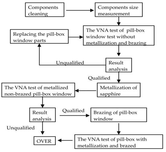
Figure 8.
The test flow chart for the over-size pillbox window.
It is worth mentioning that, when formulating a pill-box window soldering plan, the solder should be isolated from the cavity waveguide in the pill-box window, that is, the solder slot in the soldering plan should be a closed space, as shown in Figure 9a. The deformation of the solder in the high-temperature furnace under the high pressure of the fixture should be controlled. This can reduce the influence of transmission characteristics of the over-size pill-box window by solder deformation. According to the structural parameters optimized by the simulation, the components of the over-size pill-box window are processed; the overall pill-box window after brazing is shown in Figure 9b. The experimental system of the over-size pill-box window is shown in Figure 8.
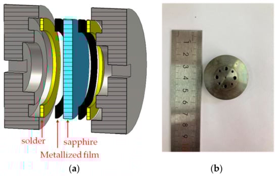
Figure 9.
(a) The b razing diagram of the window system (b) The pillbox windows after brazing assembly.
From the experimental process of the pill-box window, it can be seen that each successful window needs three tests on the VNA. In the first test, the non-metalized dielectric window sheet and other components were assembled into a pill-box window system with screws and pins. The test results on VNA are shown in Figure 10. It can be seen from the figure that there is a large reflection at 214.3 GHz, the transmission loss reaches -2 dB, and the spurious modes are produced at the frequency of 221.9 GHz. The reason for this phenomenon may be that the annular air grooves on both sides of the tested pill-box window dielectric sheet affect the transmission characteristics of the window system. This can be verified by a simulation calculation. The ring-shaped hollow groove with a ring width of 0.5 mm and a ring height of 0.2 mm on both sides of the dielectric sheet are added to the simulation calculation, and the result is shown in Figure 11. There is a larger reflection point at 213.5 GHz in the simulation result, which is 0.9 GHz different from the frequency of the reflection point in the test result. The two results are quite similar. It can be determined that this reflection point is the influence of the ring-shaped groove on the transmission of the pill-box window. The test results have good overall transmission characteristics after removing the spurious mode points in the 215–225 GHz frequency band, and are highly similar to the simulation results. This shows that the processing error of the tested pill-box window parts is small, and the next test can be carried out.
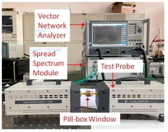
Figure 10.
Experimental testing of the pill-box windows.
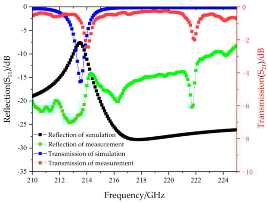
Figure 11.
Results of the non-metallization and non-brazed pill-box windows.
After the first test of the pill-box window, the dielectric window sheet is metalized and then assembled and tested. In this case, the ring-shaped solder grooves on both sides of the dielectric sheet are blocked by the metalized film, and the transmission effect on the pill-box window is negligible. With the support of mature metallization and brazing technology, the results of the last two tests are basically the same. The final test results are shown in Figure 12. It can be seen from the figure that there is a large gap between the tested pill-box window transmission coefficient and the simulated value, but the numerical trend is very similar. In the design frequency band 215–225 GHz, the over-size pill-box window has good transmission characteristics, its maximum transmission loss is −1 dB, the overall transmission loss is close to −0.5 dB, and the overall reflection is less than −11 dB. Its characteristics fully meet the parameter requirements as an input window.
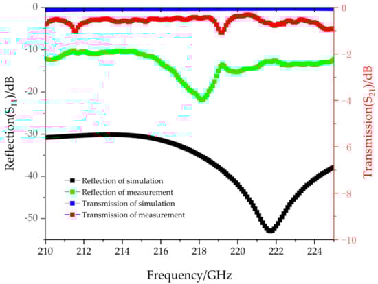
Figure 12.
Results of the metallization and brazed pill-box windows.
4. Conclusions
This paper introduces the design, production and testing of a pill-box window developed for G band VEDs. The tolerance of the circular waveguide length (L1) of the pill-box window in the different radius mediums of the improved pill-box window is discussed, which effectively provides a higher tolerance of the box-shaped window to the length of the circular waveguide. This provides a new idea for the selection of the radius of the dielectric sheet of this type window. After the theoretical calculation and simulation optimization, the reflection of the box window in the 210–230 GHz frequency band was less than −30 dB, and the maximum transmission loss was −0.2 dB. The problems of the experiment process and optimized the test process are summarized. The test results of pill-box windows without metallization and brazing are shown. The simulation analysis on test results was performed to determine the eligibility of pill-box window components. The pill-box window was within the design frequency band of 215–225 GHz, the overall transmission loss was close to −0.5 dB, and the overall reflection was −11 dB. The test results show that this over-size pill-box window is a design that can be applied to the vacuum window of a sub-THz VEDs, and has development potential at higher terahertz region frequencies.
Author Contributions
T.Y. and W.F. contributed to the overall study design, analysis, computer simulation, and writing of the manuscript. X.G., D.L., J.X., C.Z., X.Y., and Y.Y. provided technical support and revised the manuscript. All authors have read and agreed to the published version of the manuscript.
Funding
This work was supported in part by National Key Research and Development Program of China under 2019YFA0210202, in part by the National Natural Science Foundation of China under Grant 61971097 and 6201101342, and in part by the Terahertz Science and Technology Key Laboratory of Sichuan Province Foundation under Grant THZSC201801.
Acknowledgments
The authors gratefully acknowledge Yin Huang and Weirong Deng for their kind assistance on engineering design and assembling.
Conflicts of Interest
The authors declare no conflict of interest.
References
- Lin, M.C.; Chung, H.M.; Burke, A. An analytical approach for the fast design of high-power waveguide windows. Wave Motion 2003, 37, 183–188. [Google Scholar] [CrossRef]
- Donaldson, C.R.; He, W.; Zhang, L.; Cross, A.W. A W-band multilayer microwave window for pulsed operation of gyro-devices. IEEE Microw. Wirel. Compon. Lett. 2013, 23, 237–239. [Google Scholar] [CrossRef]
- Cook, A.M.; Joye, C.D.; Kimura, T.; Wright, E.L.; Calame, J.P. Broadband 220-GHz vacuum window for a traveling-wave tube amplifier. IEEE Trans. Electron. Devices 2013, 60, 1257–1259. [Google Scholar] [CrossRef]
- Ao, H.; Asano, H.; Naito, F.; Ouchi, N.; Tamura, J.; Takata, K. Impedance matching of pillbox-type RF windows and direct measurement of the ceramic relative dielectric constant. Nucl. Instrum. Methods Phys. Res. Sect. A Accel. Spectrom. Detect. Assoc. Equip. 2014, 737, 65–70. [Google Scholar] [CrossRef]
- Zhang, L.; Donaldson, C.R.; Cross, A.W.; He, W. A Pillbox window with impedance Matching Sections for a W-Band Gyro-TWA. IEEE Electron Device Lett. 2018, 39, 1081–1084. [Google Scholar] [CrossRef]
- Yang, T.; Guan, X.; Fu, W.; Lu, D.; Zhang, C.; Xie, J.; Yuan, X.; Yan, Y. Investigation on Symmetric and Asymmetric Broadband Low-Loss W-Band Pillbox Windows. Electronics 2020, 9, 2060. [Google Scholar] [CrossRef]
- Cai, J.; Hu, L.; Ma, G.; Chen, H.; Jin, X.; Chen, H. Theoretical and Experimental Study of the Modified Pill-Box Window for the 220-GHz Folded Waveguide BWO. IEEE Trans. Plasma Sci. 2014, 42, 3349–3357. [Google Scholar] [CrossRef]
- Arai, H.; Goto, N.; Ikeda, Y.; Imai, T. An analysis of a vacuum window for lower hybrid heating. IEEE Trans. Plasma Sci. 1986, 14, 947–954. [Google Scholar] [CrossRef]
- Liu, S. A RF window for broadband millimeter wave tubes. Int. J. Infrared Millim. Waves 1996, 17, 121–126. [Google Scholar] [CrossRef]


Publisher’s Note: MDPI stays neutral with regard to jurisdictional claims in published maps and institutional affiliations. |
© 2021 by the authors. Licensee MDPI, Basel, Switzerland. This article is an open access article distributed under the terms and conditions of the Creative Commons Attribution (CC BY) license (http://creativecommons.org/licenses/by/4.0/).