Article

Broadband Dual-Polarized 2 × 2 MIMO Antenna for a 5G Wireless Communication System

1
Department of Industrial Engineering, Yonsei University, Seoul 03722, Korea
2
Department of Electronic Convergence Engineering, Kwangwoon University, Seoul 01897, Korea
3
MinongBio Company Limited, Seoul 01886, Korea
4
Korea Electronics Technology Institute, Seongnam 13509, Korea
*
Author to whom correspondence should be addressed.
Electronics 2021, 10(17), 2141; https://doi.org/10.3390/electronics10172141
Submission received: 10 August 2021 / Revised: 29 August 2021 / Accepted: 1 September 2021 / Published: 2 September 2021
(This article belongs to the Special Issue Antennas in the 5G System)

Abstract

:
In this study, we proposed an indoor broadband dual-polarized 2 × 2 MIMO (multiple-input and multiple-output) antenna having dimensions of 240 mm × 200 mm × 40 mm, for application in 5G wireless communication systems. The proposed antenna comprised two vertically polarized circular monopole antennas (CMAs), two horizontally polarized modified rectangular dipole antennas (MRDAs), and a ground plane. The distance between the two MRDAs (MRDA1 and MRDA2) was 70.5 mm and 109.5 mm in the horizontal (x-direction) and 109.5 mm vertical (y-direction) directions, respectively. Conversely, the distance between the two CMAs (CMA1 and CMA2) was 109.5 mm and 70.5 mm in the horizontal (x-direction) and vertical (y-direction) directions, respectively. While the CMAs achieved broadband characteristics owing to the optimal gap between the dielectric and the driven radiator using a parasitic element, the MRDAs achieved broadband owing to the optimal distance between the dipole antennas. The observations in this experiment confirmed that the proposed could operate in the 5G NR n46 (5.15–5.925 GHz), n47 (5.855–5.925 GHz), n77 (3.3–4.2 GHz), n78 (3.3–3.8 GHz), and the n79 (4.4–5 GHz) bands. Moreover, it exhibited a wide impedance bandwidth (dB magnitude of S 11 ) of 101% in the 2.3–7 GHz frequency range, high isolation (dB magnitude of S 21 ), low envelope coefficient correlation (ECC), gain of over 5 dB, and average radiation efficiency of 87.19%, which verified its suitability for application in sub-6 GHz 5G wireless communication systems.

1. Introduction

Mid-band 5G, also called the mid sub-6 GHz band, is gaining widespread attention owing to the intensive usage by general 5G subscribers. While some countries have considered expanding their 5G frequency band above 4 GHz, other countries have already done so [1]. Among the various mid sub-6 GHz bands, the n77 (3300–4200 MHz) and n78 (3300–3800 MHz) bands have been widely adopted in several countries; this is only feasible by using a sub-6 GHz 5G antenna operating in the n46 (5150–5925 MHz), n47 (5855–5925 MHz), and n79 (4400–5000 MHz) bands. A high channel capacity, dual-polarization, and broadband are essential factors for wireless communication [2].
The most popular method to realize a broadband dipole antenna is using two orthogonal crossed-dipole antennas with a reflector or cavity [3,4,5,6,7]. However, it is difficult to achieve bandwidth over 100% using the conventional crossed-dipole MIMO antenna. The conventional structures for which it is difficult to achieve broadband characteristics cannot cover all 5G bands in the current situation of expanding 5G bands. In addition, crossed-dipole antennas have little space between the ports. The lack of space between the ports makes it difficult to use relatively big N-type connectors which widely use the wireless industry and wireless modules. However, the hybrid monopole/dipole structure gives sufficient space between the ports. It makes it easier to use a relatively big N-type connector and connect the antenna with a wireless module.
Many studies on broadband monopole antennas with a parasitic element have been reported [8,9,10]. In study [8], a novel dual band notched monopole antenna with increased bandwidth is proposed. It is a radiator on top of the substrate and ground plane with L-shaped slots and a parasitic at the bottom of the substrate to enhance the bandwidth. Similarly, Refs. [9,10] proposed monopole antennas with parasitic elements.
Several MIMO antennas with shared radiator have been studied [11,12,13]. In study [11], a common radiator coplanar waveguide (CPW) fed a four port multiple-input-multiple-output (MIMO) antenna for 5G sub-1 GHz, sub-6 GHz and Wi-Fi 6 applications with a shared radiator is proposed. This antenna has relatively bad impedance bandwidth (−6 dB). Since the antenna’s impedance bandwidth should be under −10 dB of S 11 , it is not suitable for 5G wireless communication. The study [12] proposed a wideband compact Yagi-like directional MIMO antenna with a shared radiator. It also has insufficient impedance bandwidth of 28%. In addition, a wearable four port MIMO antenna with a shared radiator in [13] shows insufficient bandwidth of 4.1%. These studies show that a MIMO antenna with a shared radiator can make the antenna size compact, but it is hard to achieve impedance bandwidth over 100%.
If the MIMO antenna does not have a shared radiator and is composed of independent radiators, it must have considered high isolation and mutual coupling between each radiator. The mutual coupling suppression between independent radiators is essential for the high isolation. There are several mutual coupling suppression techniques such as neutralization lines [14,15], defected ground structure [16,17,18], pin or varactor diode [19,20,21,22], electromagnetic bandgap decoupling structure [23], etc. The easiest way to increase the isolation is to increase the distance between the radiators.
In this study, we propose a simple broadband monopole antenna with a parasitic element and dipole antenna composing a dual-polarized 2 × 2 multi-input multi-output (MIMO) antenna. This MIMO antenna comprises two circular monopole antennas (CMAs) and two modified rectangular dipole antennas (MRDAs) in different biased directions for dual polarization in indoor 5G wireless communication systems. The proposed MIMO antenna exhibited a wide impedance bandwidth (dB magnitude of S 11 ), high isolation (dB magnitude of S 21 ), and low envelope correlation coefficient.

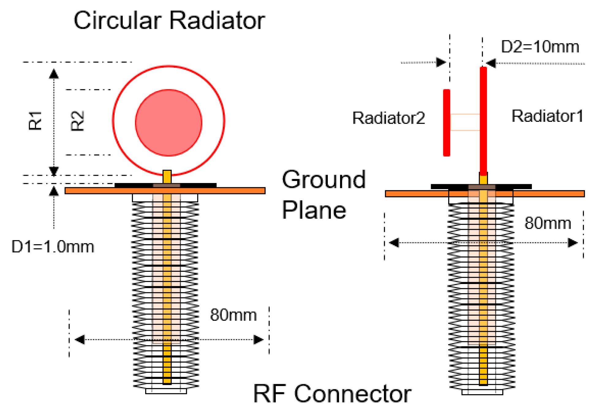
2. Single Antenna Element
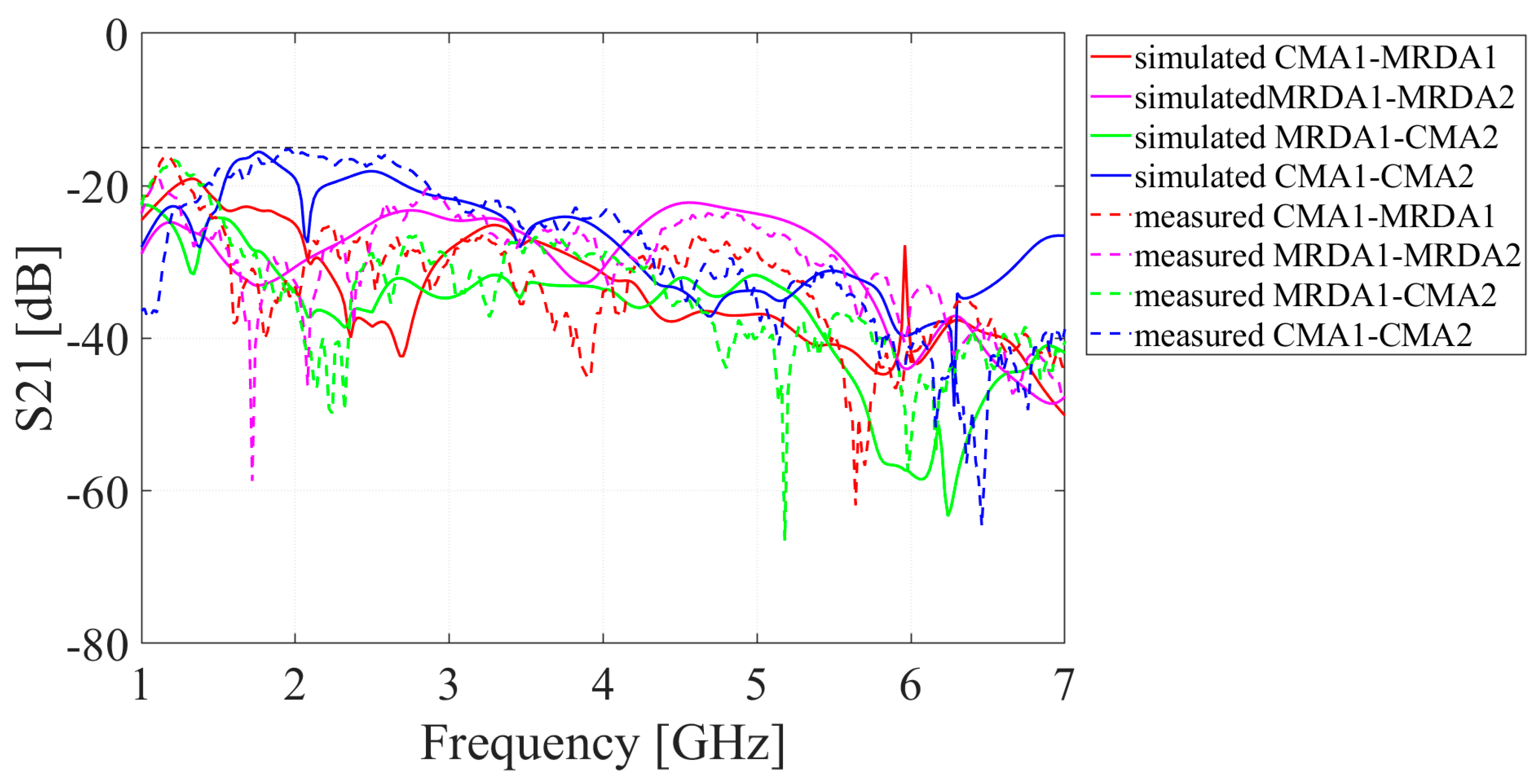
Figure 1 shows the CMA used in this study. The antenna had dimensions 80 mm × 80 mm × 33 mm and comprised driven circular and parasitic circular radiators manufactured on a 0.8 mm thick FR4 substrate ( ε r = 4.4, tan δ = 0.02) and a ground plane. The driven radiator (R1), having a diameter of 32 mm (≈λ/2 at 2.2 GHz), was used to determine the resonant frequency, and the driven element was the impedance matched with the gap between the dielectric and driven element. Figure 2 shows the simulated and measured values of the voltage standing wave ratio (VSWR) based on the distance between the driven element and the dielectric (D1). An EM simulation tool Ansys HFSS was used to simulate. It was observed that the smaller the gap between the driven element and ground plane, the better the impedance match. The parasitic radiator (R2), having a diameter of 10 mm (≈λ/2 at 7 GHz), was used to analyze the wide impedance bandwidth. Figure 3 shows the simulated and measured CMA S 11 values in the presence and absence of the parasitic element.
Figure 4 shows the three different versions of the MRDA. Figure 4a shows the first version of the MRDA. It has no notch at the edge of radiator. Figure 4b,c show the second and final versions of the MRDA. The final version of the MRDA achieved a wide impedance bandwidth owing to an added slot at the edge of radiators. Figure 5 shows the S 11 value of the first, second, and final versions of the MRDA. It shows that the final version of MRDA has the widest impedance bandwidth of 142.77% (6.23–1.04 GHz).
Figure 6 shows the proposed MRDA, which is used in this study. The antenna had dimensions 100 mm × 100 mm × 30 mm, and comprised radiators (+ and −), a feeding line fabricated on a 1.6 mm thick FR4 substrate ( ε r = 4.4, tan δ = 0.02), and a ground plane. Radiator (+) and the feed line were designed on the top layer of the MRDA, whereas radiator (−) was designed on the bottom layer.
Figure 7 shows the simulated and measured VSWR values based on the distance between the radiators in the presence and absence of the ground plane. It was observed that the antenna exhibits the widest impedance bandwidth in the absence of the ground plane. However, the ground plane, which acts as a reflector, was introduced to improve the gain of the MRDA.

3. MIMO Antenna

Figure 8 illustrates the 2 × 2 MIMO antenna with four CMAs. The overall dimensions of the MIMO antenna with four CMAs were 250 mm × 250 mm × 34.6 mm. The CMA1 and CMA3 were vertically polarized and the CMA2 and CMA4 were horizontally polarized. To the CMA, the ground plane is an electrical ground plane. The distances between each CMA were 142.5 mm in the horizontal (x-direction) and 142.5 mm vertical (y-direction) directions, respectively.
Figure 9 shows the S 11 of the MIMO antenna with four CMAs and Figure 10 shows S 21 of the fo MIMO antenna with four CMAs. The MIMO antenna with four CMAs has simulated bandwidth of 118.9% (1.78–7 GHz) and has peak isolation of 15.4 dB at 2.38 GHz. It shows that the MIMO antenna with four CMAs is suitable for 5G wireless communication. However, the MIMO antenna with four CMAs size is large. To reduce the size of the MIMO antenna, this study proposed a hybrid structure MIMO antenna with two CMAs and two MRDAs.
Figure 10 illustrates the proposed broadband dual-polarized 2 × 2 MIMO antenna. The overall dimensions of the antenna were 242 mm × 200 mm × 40 mm. The two CMAs and MRDAs were vertically and horizontally polarized, respectively. To the CMA, the ground plane is an electrical ground plane. However, the ground plane is not connected to the MRDA, and it acts as a reflector. The distances between the two MRDAs (MRDA1 and MRDA2) were 70.5 mm and 109.5 mm in the horizontal (x-direction) and 109.5 mm vertical (y-direction) directions, respectively. Conversely, the distance between the two CMAs (CMA1 and CMA2) was 109.5 mm and 70.5 mm in the horizontal (x-direction) and vertical (y-direction) directions, respectively. Figure 11 shows the prototype of the proposed 2 × 2 MIMO antenna.
Figure 12 shows the simulated and measured S 11 values of the proposed antenna. The measured impedance bandwidth of CMA1 and CMA2 (dB magnitude S 11 ) was 113.2% (1.94–7 GHz), and that of MRDA1 and MRDA2 (dB magnitude of S 11 ) was 101% (2.3–7 GHz). The proposed antenna operated successfully the 5G NR n46 (5.15–5.925 GHz), n47 (5.855–5.925 GHz), n77 (3.3–4.2 GHz), n78 (3.3–3.8 GHz), and n79 (4.4–5 GHz) bands. Figure 13 shows the simulated and measured S 21 values of the proposed 2 × 2 MIMO antenna. The isolation between CMA1 and CMA2 is relatively low in the frequency range 1.4–2.88 GHz, which can be improved by increasing the distance between them. However, as the distance between CMA1 and CMA2 increases, the gain decreases relatively. Therefore, the distance between CMA1 and CMA2 was traded off to meet the requirements of isolation and gain.
The envelope correlation coefficient (ECC) can be defined by Equation (1):
ρ e = F 1 θ , ϕ F 2 θ , ϕ d Ω 2 F 1 θ , ϕ 2 d Ω F 2 θ , ϕ 2 d Ω
In Equation (1), F n θ , ϕ is the field radiation pattern of the antenna at port n. Solving this equation is a complex process, and the field radiation pattern is essential. The field radiation pattern can be defined as Equation (2). In Equation (2), D n is maximum directivity of the antenna. By using Equation (2), the ECC can be calculated as expressed in Equation (3) [24]. Figure 14 shows the envelope correlation coefficient (ECC) measurements based on the simulated and measured S-parameters:
D 1 4 π F 1 θ , ϕ 2 d Ω = 1 S 11 2 + S 21 2
ρ e = S 11 S 12 + S 21 S 21 2 1 S 11 2 + S 21 2 1 S 22 2 + S 12 2
Figure 15 shows the simulated and measured peak gain. The antenna exhibited a gain of over 5 dB in the 2–6 GHz band. The MRDA exhibited a peak gain of 9.6 dB at 5 GHz and the CMA exhibited a peak gain of 7.07 dB at 4.5 GHz. In addition, it exhibited average measured radiation efficiency (gain to directivity ratio) of 87.19%.
Figure 16 shows the simulated and measured XZ-plane (E-plane) and XY-plane (H-plane) radiation pattern of the CMA at 3.5 GHz and 5.5 GHz. For CMA, vertical polarization is co-polarization and horizontal polarization is cross-polarization. The figure shows that the simulated and measured CMA has a quasi-omnidirectional radiation pattern at both 3.5 and 5.5 GHz.
Figure 17 shows the simulated and measured YZ-plane (E-plane) and XY-plane (H-plane) radiation pattern of the MRDA at 3.5 GHz and 5.5 GHz. For MRDA, vertical polarization is cross-polarization and horizontal polarization is co-polarization. The figure shows that the simulated and measured MRDA has a quasi-directional radiation pattern at both 3.5 and 5.5 GHz.
Table 1 presents a comparison among various existing wide band MIMO antennas and the proposed broadband MIMO antenna. It is observed that the proposed antenna provides the widest bandwidth. The proposed MIMO antenna has a bandwidth of 2.3–7 GHz (101.07%) and low envelope correlation coefficient under 0.1 at the operating frequency. It also has a peak gain of 9.69 dBi at 5 GHz.

4. Conclusions

In this study, we proposed a broadband dual-polarized 2 × 2 MIMO antenna for application in 5G wireless communication systems, comprising two vertically polarized circular monopole antennas, two horizontally polarized modified rectangular dipole antennas, and a ground plane. The CMAs achieved broadband characteristics owing to the distance between the driven element and the dielectric, using a parasitic element, whereas the MRDAs achieved broadband characteristics owing to the distance between the radiators. The dimensions of the proposed MIMO antenna were 242 mm×200 mm×40 mm, and it exhibited an impedance bandwidth (dB magnitude of S 11 ) of 101% (2.3–7 GHz). The isolation between the antennas was over 20 dB in the 5G NR n46 (5.15–5.925 GHz), n47 (5.855–5.925 GHz), n77 (3.3–4.2 GHz), n78 (3.3–3.8 GHz), and n79 (4.4–5 GHz) bands. The peak gain was observed to be over 5 dB. The results of this study verify that the proposed 2 × 2 MIMO antenna is suitable for application in indoor 5G wireless communication systems.

Author Contributions

Conceptualization, C.-S.L. and J.C.; methodology, H.L. (Hakyoung Lee); software, I.K.; validation, I.K., H.L. (Hakyoung Lee) and H.L. (Hojun Lee); formal analysis, C.-S.L.; investigation, C.-S.L.; resources, H.L. (Hojun Lee); data curation, I.K.; writing—original draft preparation, C.-S.L.; writing—review and editing, J.C.; visualization, I.K.; supervision, J.C.; project administration, J.C. All authors have read and agreed to the published version of the manuscript.

Funding

This research received no external funding.

Conflicts of Interest

The authors declare no conflict of interest.

References

  1. Qualcomm. “Global Update on Spectrum for 4G & 5G”. December 2020. Available online: https://www.qualcomm.com/media/documents/files/spectrum-for-4g-and-5g.pdf (accessed on 9 August 2021).
  2. Nishimori, K.; Makise, Y.; Ida, M.; Kudo, R.; Tsunekawa, K. Channel Capacity Measurement of 8 × 2 MIMO Transmission by Antenna Configurations in an Actual Cellular Environment. IEEE Trans. Antennas Propag. 2006, 54, 3285–3291. [Google Scholar] [CrossRef]
  3. Ta, S.X.; Nguyen, D.M.; Nguyen, K.K.; Ngoc, C.C.; Trong, N.N. Wideband Differentially Fed Dual-Polarized Antenna for Existing and Sub-6 GHz 5G Communications. IEEE Antennas Wirel. Propag. Lett. 2020, 19, 2033–2037. [Google Scholar] [CrossRef]
  4. Zhou, G.-N.; Sun, B.-H.; Liang, Q.-Y.; Wu, S.-T.; Yang, Y.-H.; Cai, Y.-M. Triband Dual-Polarized Shared-Aperture Antenna for 2G/3G/4G/5G Base Station Applications. IEEE Trans. Antennas Propag. 2021, 69, 97–108. [Google Scholar] [CrossRef]
  5. Hua, Q.; Huang, Y.; Alieldin, A.; Song, C.; Jia, T.; Zhu, X. A Dual-Band Dual-Polarized Base Station Antenna Using a Novel Feeding Structure for 5G Communications. IEEE Access 2020, 8, 63710–63717. [Google Scholar] [CrossRef]
  6. Tang, H.; Zong, X.; Nie, Z. Broadband Dual-Polarized Base Station Antenna for Fifth-Generation (5G) Applications. Sensors 2018, 18, 2701. [Google Scholar] [CrossRef] [Green Version]
  7. Wen, S.; Dong, Y. A Low-Profile Wideband Antenna with Monopole like Radiation Characteristics for 4G/5G Indoor Micro Base Station Application. IEEE Antennas Wirel. Propag. Lett. 2020, 19, 2305–2309. [Google Scholar] [CrossRef]
  8. Alsariera, H.; Zakaria, Z.; Awang Md Isa, A. A Broadband P-Shaped Circularly Polarized Monopole Antenna with a Single Parasitic Strip. IEEE Antennas Wirel. Propag. Lett. 2019, 18, 2194–2198. [Google Scholar] [CrossRef]
  9. Zaker, R.; Ghobadi, C.; Nourinia, J. Bandwidth Enhancement of Novel Compact Single and Dual Band-Notched Printed Monopole Antenna with a Pair of L-Shaped Slots. IEEE Trans. Antennas Propag. 2009, 57, 3978–3983. [Google Scholar] [CrossRef]
  10. Meng, L.; Wang, W.; Su, M.; Gao, J.; Liu, Y. Bandwidth Extension of a Printed Square Monopole Antenna Loaded with Periodic Parallel-Plate Lines. Int. J. Antennas Propag. 2017, 2017, 4082780. [Google Scholar] [CrossRef] [Green Version]
  11. Jha, K.R.; Jibran, Z.A.P.; Singh, C.; Sharma, S.K. 4-Port MIMO Antenna Using Common Radiator on a Flexible Substrate for Sub-1GHz, Sub-6GHz 5G NR, and Wi-Fi 6 Applications. IEEE Open J. Antennas Propag. 2021, 2, 689–701. [Google Scholar] [CrossRef]
  12. Jehangir, S.S.; Sharawi, M.S. A Compact Single-Layer Four-Port Orthogonally Polarized Yagi-Like MIMO Antenna System. IEEE Trans. Antennas Propag. 2020, 68, 6372–6377. [Google Scholar] [CrossRef]
  13. Wagih, M.; Hilton, G.S.; Weddell, A.S.; Beeby, S. Dual-Polarized Wearable Antenna/Rectenna for Full-Duplex and MIMO Simultaneous Wireless Information and Power Transfer (SWIPT). IEEE Open J. Antennas Propag. 2021, 2, 844–857. [Google Scholar] [CrossRef]
  14. Wang, Y.; Du, Z. A Wideband Printed Dual-Antenna with Three Neutralization Lines for Mobile Terminals. IEEE Trans. Antennas Propag. 2014, 62, 1495–1500. [Google Scholar] [CrossRef]
  15. Su, S.; Lee, C.; Chang, F. Printed MIMO-Antenna System Using Neutralization-Line Technique for Wireless USB-Dongle Applications. IEEE Trans. Antennas Propag. 2012, 60, 456–463. [Google Scholar] [CrossRef]
  16. Khandelwal, M.K.; Kanaujia, B.K.; Kumar, S. Defected ground structure: Fundamentals analysis and applications in modern wireless trends. Int. J. Antennas Propag. 2017, 2017, 2018527. [Google Scholar] [CrossRef]
  17. Lindberg, P.; Morton, L.; Kaikkonen, A.; Cheng, S.; Hallbjorner, P. Technique of ground size tuning for isolation between monopoles in compact wireless terminals. IEEE Trans. Antennas Propag. 2012, 60, 5488–5491. [Google Scholar] [CrossRef]
  18. Lu, J.; Kuai, Z.; Zhu, X.; Zhang, N. A high-isolation dual-polarization microstrip patch antenna with quasi-cross-shaped coupling slot. IEEE Trans. Antennas Propag. 2011, 59, 2713–2717. [Google Scholar] [CrossRef]
  19. Piazza, D.; Kirsch, N.J.; Forenza, A.; Heath, R.W.; Dandekar, K.R. Design and evaluation of a reconfigurable antenna array for MIMO systems. IEEE Trans. Antennas Propag. 2008, 56, 869–880. [Google Scholar] [CrossRef]
  20. Hussain, R.; Sharawi, M.S.; Shamim, A. An Integrated Four-Element Slot-Based MIMO and a UWB Sensing Antenna System for CR Platforms. IEEE Trans. Antennas Propag. 2018, 66, 978–983. [Google Scholar] [CrossRef] [Green Version]
  21. Hussain, R.; Sharawi, M.S.; Shamim, A. 4-Element Concentric Pentagonal Slot-Line-Based Ultra-Wide Tuning Frequency Reconfigurable MIMO Antenna System. IEEE Trans. Antennas Propag. 2018, 66, 4282–4287. [Google Scholar] [CrossRef]
  22. Lim, J.; Jin, Z.; Song, C.; Yun, T. Simultaneous Frequency and Isolation Reconfigurable MIMO PIFA Using PIN Diodes. IEEE Trans. Antennas Propag. 2012, 60, 5939–5946. [Google Scholar] [CrossRef]
  23. Alam, M.S.; Misran, N.; Yatim, B.; Islam, M.T. Development of electromagnetic band gap structures in the perspective of microstrip antenna design. Int. J. Antennas Propag. 2013, 2013, 507158. [Google Scholar] [CrossRef]
  24. Blanch, S.; Romeu, J.; Corbella, I. Exact Presentation of antenna system diversity performance from input parameter description. Electron. Lett. 2003, 39, 705–707. [Google Scholar] [CrossRef] [Green Version]
  25. Zhou, X.; Quan, X.; Li, R. A Dual-Broadband MIMO Antenna System for GSM/UMTS/LTE and WLAN Handsets. IEEE Antennas Wirel. Propag. Lett. 2012, 11, 551–554. [Google Scholar] [CrossRef]
  26. Ding, K.; Gao, C.; Qu, D.; Yin, Q. Compact Broadband MIMO Antenna with Parasitic Strip. IEEE Antennas Wirel. Propag. Lett. 2017, 16, 2349–2353. [Google Scholar] [CrossRef]
  27. Lee, H.; Lee, B. Compact Broadband Dual-Polarized Antenna for Indoor MIMO Wireless Communication Systems. IEEE Trans. Antennas Propag. 2016, 64, 766–770. [Google Scholar] [CrossRef]
  28. Moradi, A.; Rahman, T.A.; Khalily, M. Common Elements Wideband MIMO Antenna System for WiFi/LTE Access-Point Applications. IEEE Antennas Wirel. Propag. Lett. 2014, 13, 1601–1604. [Google Scholar]
  29. Li, W.T.; Hei, Y.Q.; Subbaraman, H.; Shi, X.W.; Chen, R.T. Novel Printed Filtenna with Dual Notches and Good Out-of-Band Characteristics for UWB-MIMO Applications. IEEE Microw. Wirel. Compon. Lett. 2016, 26, 765–767. [Google Scholar] [CrossRef]
  30. Peng, H.; Zhi, R.; Yang, Q.; Cai, J.; Wan, Y.; Liu, G. Design of a MIMO Antenna with High Gain and Enhanced Isolation for WLAN Applications. Electronics 2021, 10, 1659. [Google Scholar] [CrossRef]
Figure 1. Overall dimensions of a circular monopole antenna (CMA).
Electronics 10 02141 g001
Figure 2. Simulated and measured voltage standing wave ratio (VSWR) according to the distance between the driven element and dielectric (D1).
Electronics 10 02141 g002
Figure 3. Simulated and measured CMA return loss with and without parasitic elements.
Electronics 10 02141 g003
Figure 4. Three different versions of MRDA (modified rectangular dipole antennas): (a) version1, (b) version2, and (c) final version.
Electronics 10 02141 g004
Figure 5. Simulated S 11 values of three different versions of MRDA.
Electronics 10 02141 g005
Figure 6. Overall dimensions of MRDA.
Electronics 10 02141 g006
Figure 7. Simulated and measured MRDA VSWR values depending on the height of the ground plane.
Electronics 10 02141 g007
Figure 8. 2 × 2 MIMO (multiple-input and multiple-output) antenna with four CMAs.
Electronics 10 02141 g008
Figure 9. (a) Simulated S 11 values of the 2 × 2 MIMO antenna with four CMAs; (b) simulated S 21 values of the CMAs 2 × 2 MIMO antenna with four CMAs.
Electronics 10 02141 g009
Figure 10. Proposed 2 × 2 MIMO antenna: (a) overall view; (b) top view.
Electronics 10 02141 g010aElectronics 10 02141 g010b
Figure 11. Prototype of 2 × 2 MIMO antenna: (a) top view; (b) side view.
Electronics 10 02141 g011
Figure 12. Simulated and measured S 11 values of the proposed broadband dual-polarized 2 × 2 MIMO antenna.
Electronics 10 02141 g012
Figure 13. Simulated and measured S 21 values of the proposed broadband dual-polarized 2 × 2 MIMO antenna.
Electronics 10 02141 g013
Figure 14. Simulated and measured ECC (envelope correlation coefficient) of the proposed broadband dual-polarized 2 × 2 MIMO antenna.
Electronics 10 02141 g014
Figure 15. Simulated and measured peak gain of the proposed broadband dual-polarized 2 × 2 MIMO antenna.
Electronics 10 02141 g015
Figure 16. Simulated and measured CMA radiation pattern in (a) 3.5 GHz XY-plane; (b) 3.5 GHz XZ-plane; (c) 5.5 GHz XY-plane; and (d) 5.5 GHz XZ-plane.
Electronics 10 02141 g016
Figure 17. Simulated and measured MRDA radiation pattern in (a) 3.5GHz XY-plane; (b) 3.5GHz YZ-plane; (c) 5.5GHz XY-plane; and (d) 5.5GHz YZ-plane.
Electronics 10 02141 g017
Table 1. Comparison between the existing wide band MIMO antennas and proposed MIMO antenna.
ReferencePort NumberOperating Frequency (GHz)Antenna SizeEnhance Bandwidth TechniqueIsolationPeak GainECC
[25]21.5–2.8 (60%)
4.7–8.5 (58%)
0.25λ × 0.31λ × 0.004λSlot15 dB<7 dBi<0.01
[26]42.32–2.95 (23.9%)0.57λ × 0.57λ × 0.22λSlot17 dB<7 dBi<0.003
[27]21.71–2.69 (44.5%)0.78λ × 0.78λ × 0.31λSlot30 dB<7 dBi<0.00425
[28]41.8–2.9 (46.8%)0.84λ × 0.72λ × 0.009λSlot15 dB<10 dBi<0.1
[29]23.1–3.35 (7.75%)
3.55–5.65 (45.65%)
5.95–10.65 (88.59%)


0.36λ × 0.7λ × 0.01λ


Notch


20 dB<


4.2 dBi


<0.002
[30]22.12–2.8 (27.6%)
4.95–6.65 (29.3%)

0.35λ × 0.28λ × 0.01λ

Parasitic element

15 dB<

6.4 dBi

<0.024
Proposed42.3–7 (101%)1.53λ × 1.85λ × 0.3λParasitic element
Notch
15 dB<9.69 dBi<0.1
Publisher’s Note: MDPI stays neutral with regard to jurisdictional claims in published maps and institutional affiliations.

