Abstract
The usage of BLDC motors in the low-power range is increasing rapidly in home appliances such as ceiling fans. This has necessitated the development of reliable, compact and efficient AC-DC power supplies for motor drive circuitry. This paper presents a power supply design consisting of an AC-DC isolated PFC Cuk converter with integrated magnetics that supplies a single-shunt voltage source inverter for the sensorless drive of the BLDC fan motor. The proposed power supply design is comprised of an integrated magnetics structure in which the two inductors and the transformer windings share the same core. The zero input and output ripple current conditions have been derived from the reluctance model of the magnetic assembly. Smooth operation of the motor by minimizing the motor torque ripples is evident from the results. The Cuk converter operates in continuous conduction mode (CCM), employing the current multiplier method. The CCM-based current multiplier control loop ensures a near-unity power factor as well as low total harmonic distortion in the supply current. The current loop also provides over-current protection, enhancing reliability of the system. Moreover, the speed of the BLDC motor is controlled by the field oriented control (FOC) algorithm, which enables direct operation with alternate energy sources such as batteries and solar photovoltaic panels. The performance of the proposed supply is validated: motor torque ripple is reduced to only 2.14% while maintaining 0.999 power factor and only 4.72% THD at full load. Failure modes analysis has also been performed through software simulations, using the PLECS simulation environment. Due to the reliable power supply design with low ripples, it is well suited for low-power BLDC motors in home appliances and small power tools, in addition to ceiling fans.
1. Introduction
Electrical and electronic equipment design in the 21st century is invariably focused on energy efficiency. Most home appliances have already been replaced by energy efficient upgrades: inverter-based designs have replaced conventional solutions for air conditioners and refrigerators, LEDs have supplanted fluorescent lights, and LED TVs have substituted CRT-based televisions, to name a few examples [1]. Among all household appliances, electric fans are one of the most widespread in both urban and rural environments [2]. Ceiling fans are extensively used in summer seasons all around the world, constituting approximately 6–9% of the total energy used in the residential sector. Improvements in ceiling fan design offer enormous potential for energy savings. The most significant improvement is the use of a brushless DC (BLDC) motor in place of an induction motor, which can reduce power consumption by 50% [3,4]. Although the technology of permanent magnet BLDC motors for fans is more complex, the rising energy cost has tipped the return on investment in its favor [5,6]. Two types of PM motors are currently being well received for ceiling fan applications, namely the BLDC motor and the permanent magnet synchronous motor (PMSM). Both these machines are very similar, except that the BLDC has a trapezoidal back EMF, while the PMSM has a sinusoidal back EMF. BLDC motors are commonly used in designs that require cost-effective solutions, due to their low cost of manufacturing [7].
A comparison of induction motors with BLDC and PMSM motors is given in Table 1. The usage of BLDC motors is substantially increasing in ceiling fans as well as other household appliances. These appliances are commonly powered by single-phase utility electricity supply, which is rated country-wise as 220 V (50 Hz) or 110 V (60 Hz). DC-DC converters are used to convert this single-phase AC to the required DC Voltage levels that are fed to a voltage source inverter (VSI). A combination of this DC-DC converter and the VSI forms a BLDC motor drive that controls the motor speed in the target appliance. The speed and torque are the output characteristics of the fan motor. Both these parameters are controlled by the sensorless field oriented control (FOC) algorithm. Even with tight regulation through properly designed control loops, torque ripple is created in BLDC motors due to changes in the stator current ripples caused by inductance and resistance in the motor windings [8,9]. This ripple can cause extremely undesirable effects such as motor vibration, acoustic noise, and other physical faults that may develop over time.

Table 1.
Comparison of motor technologies.
The torque of a BLDC motor is given in Equation (1):
where , , and represent the EMF of the motor windings. , , and represent the stator currents, and depicts the angular speed. As the angular speed will be constant in steady state operation, the magnitude of EMF across each of the windings will also remain constant. Therefore, the parameter that is responsible for the torque ripple is the stator current in each phase.
There are two main sources of stator current ripples. The first source is the commutation of the BLDC motor through the VSI that causes a ripple that has a frequency corresponding to the fundamental frequency at which the VSI is being switched. There are several mitigation strategies for this kind of ripple. First, the magnetic design of the stator and rotor can be improved by altering the machine design [10,11,12]. Other techniques include the design of a torque controller [13,14], a current shaping model [15,16], input voltage controller [17], feedforward current controller [18], and direct torque control [19,20] methods. The second source of ripple is the DC power supply of the VSI. If the DC source supplying the VSI contains current and voltage ripples, they will be reflected in the stator currents. Since motor drives are commonly supplied by DC-DC converters, the output ripples of the converter will have a frequency that corresponds to the switching frequency of the MOSFET in the DC-DC converter. In order to mitigate the stator current ripple, the output current ripple of the converter must be minimized. This is why converters that exhibit a continuous output current are suitable for BLDC motor drive applications.
In addition to the requirement of continuous output current, power supplies for BLDC motor drives must comply with IEC standards to maintain input power quality at an accepted level [21]. Presently, different topologies along with power factor correction (PFC) methods are being used in power supply designs to comply with these standards. In the open literature, several contributions have been reported regarding PFC single-phase AC-DC switch mode power supplies that exhibit near-unity PF and low THD [22]. These supplies are general purpose and may be used in a variety of applications, such as any analog or digital circuitry, motor drives, and battery chargers. However, very few efforts have been reported in the existing literature that uncover the need for better power quality, specifically for BLDC motor drives. The designs proposed in [23,24,25] and [26] are not target-specific, i.e., they may be used in any BLDC motor which is supplied by a single-phase AC power source. Table 2 shows a comparison between different BLDC motor drive designs.
Table 2.
Techniques of BLDC motor driver supply and control design as per the recent literature.
However, every application comes with some specific requirements that must be considered in the design process. Therefore, application-specific design is required in order to develop the motor drive that fulfills these specific requirements. There have been a few efforts to use different converters for the specific application of BLDC ceiling fan drives. In [27], a non-isolated buck–boost converter-based motor drive for a BLDC ceiling fan has been presented. This design is also non-isolated, hence only suitable for ceiling fans operating at high voltage. In [28,29], the use of Zeta and SEPIC (single ended primary inductance converter) converters, respectively, has been proposed for a ceiling fan motor drive. These designs are isolated and use DCM with the voltage follower technique to achieve near-unity PF and low THD. Furthermore, they vary the DC link voltage of the VSI, which is also the output of the DC-DC converter in order to vary the motor speed. This speed control method decreases the switching losses in the VSI by operating it at a lower switching frequency but increases the switch and body diode conduction losses in the high and low side switches of the VSI [30]. Table 3 shows the advantages and disadvantages of different BLDC motor driver designs for ceiling fans.
Table 3.
Techniques of BLDC ceiling fan supply and control design as per the recent literature.
Due to the above limitations, FOC has been preferred as the method of speed control for sensorless and hall-sensor-based BLDC motor drives, especially since more powerful and inexpensive microcontrollers are now readily available to handle the comprehensive computations required by FOC [31]. In [32,33], a design of a BLDC ceiling fan drive that uses FOC for speed control has been proposed. It can be inferred from the recent literature [32,33] that the designs of commercial appliances are increasingly using FOC for the speed control of motors. Another important aspect of the fan controller from the perspective of user experience is the number of pre-defined speed levels that can be set by the user. The literature indicates that the possibility of controlling the fan speed generally enhances thermal comfort for users [34]. Traditional ceiling fan motor controllers limit the control of speed to a few pre-defined levels, which may limit the comfort of the user. The stepless speed control can give more control to the user and hence more comfort.
Keeping in view the application-specific design requirements for BLDC ceiling fans, this work aims to design and test the performance of an efficient isolated Cuk converter supply with integrated magnetics for the motor drive of the BLDC fan. The significant contributions of this work are as follows:
- 1.
- Power supply design with negligible ripples: Presenting the design methodology for the development of an isolated PFC Cuk converter with integrated magnetics for low-power applications. This enables a design that is compact, efficient, and provides stable power supply with nearly zero high frequency ripples.
- 2.
- BLDC fan operation with low torque ripple: Using the Cuk converter to incorporate continuous input and output currents in the AC-DC supply design. This minimizes the current ripples and ensures less torque ripple in the BLDC fan motor.
- 3.
- IEC standards compliance: Deploying the isolated Cuk converter in continuous conduction mode (CCM) with the current multiplier technique. This enables power factor correction (PFC) and a total harmonic distortion (THD) reduction along with an additional feature of over-current protection.
- 4.
- Failure modes analysis: A comprehensive analysis with common fault conditions of the ceiling fan and their impact on the proposed power supply is presented.
The rest of this paper is organized as follows: the preliminary concepts used in this work are discussed in Section 2. The AC-DC PFC power supply topology, along with the design methodology, is discussed in Section 3. The system performance validation that includes the modeling and simulation approach is described in Section 4. The results and performance comparison with similar topologies are discussed in Section 5. The concluding remarks are presented in Section 6. Appendix A includes the list of acronyms used throughout the paper, the notations along with their units, and the parameters of the ceiling fan BLDC motor in Table A1, Table A2 and Table A3 respectively.
2. Background
Many topologies are deployed to improve power quality in AC-DC converters. They are primarily used according to the required load characteristics and power level. Figure 1 shows the classification of isolated power supplies according to their input to output voltage characteristics, namely the buck, buck–boost, and boost supplies. The buck and boost power supplies are preferred in applications where the output power requirement exceeds 500 W [22].
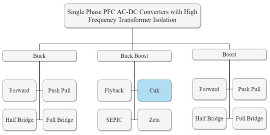
Figure 1.
Classification of isolated power supplies.
The single-phase buck–boost AC-DC converters are generally preferred and suited for low-power applications less than 500 W [22]. As represented in Figure 1, these converters are further classified as Flyback, Cuk, SEPIC, and Zeta isolated AC-DC converters. These designs have some degree of similarity as all of them offer buck–boost input to output characteristics by using a single active switching device (MOSFET) and a high frequency transformer for isolation. The transformer enables the use of multiple regulated outputs in these supplies. They may be operated in discontinuous or continuous conduction modes to improve the power quality. These converters can also be implemented with integrated magnetics to further decrease the component count, size, weight, and cost. Power quality improvement through input current shaping is extensively used in these power supplies [22].
A brief overview of the Flyback, SEPIC, Zeta, and Cuk power supply topologies is presented here. The isolated Flyback converter’s high frequency transformer provides isolation, electrical safety, lower cost, and simple control. This power supply is a popular choice in low-power applications for designers due to the lower component count and simple control [22]. The isolated Cuk converter exhibits brilliant power quality at the input AC as well as output DC side. In this design, energy is transferred through capacitors; therefore, the input and output currents are continuous. This design offers very low switching current ripple, wide range of input and output voltage, small size, natural protection against inrush current, and high overall conversion efficiency [22]. The isolated SEPIC-based power supply is another design that exhibits brilliant power quality at the input AC and output DC side. Low component count, small size, and fast dynamic response make this design a popular choice for applications where a high degree of efficiency, reliability, and power quality are required [22]. The isolated Zeta converter-based power supply is relatively new and therefore interests designers. It uses a high side switch and provides protections such as inrush current, short circuit, and overload. It is also preferred for high-power applications such as telecom power supplies and some motor drives [22].
The isolated Flyback converter has been used extensively in commercial power supply applications for decades; one limitation of this topology is that the magnetic energy is temporarily stored in the coupled circuit core. Thus, for a specific magnetic material, the maximum energy transfer is restricted by core volume. The core volume is utilized more effectively if the magnetic energy transfer is through instantaneous transformer action rather than transfer with intermediate magnetic energy storage. The other three converters address this limitation by transferring electrical energy through magnetic transformer action [35]. The results of SEPIC and Zeta converters have been reported previously in BLDC ceiling fan drives, but the isolated Cuk converter is not reported to have been tested in such an application. The SEPIC and Zeta converters exhibit continuous current on the input and output sides, respectively, whereas the Cuk converter exhibits continuous current on the input and output sides. As a result, the ripple in input and output currents is lower than the other converters. This low ripple, integrated magnetics, and low size and cost are characteristics that make the Cuk converter an interesting choice in this particular application.
3. Methodology
This section presents the design methodology of the integrated magnetics isolated Cuk converter supply for the specific application of BLDC ceiling fans. The motor driver and sensorless speed control have been used to drive the fan at the rated speed and torque. Figure 2 depicts a complete block diagram of the system design. It includes two main blocks, namely the AC-DC PFC isolated power supply and the BLDC motor drive. The former block provides stable power supply with nearly zero current ripples, while the latter block spins the motor efficiently. Each block is explained in detail below.
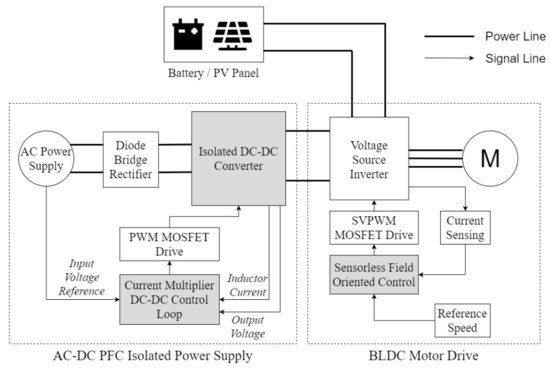
Figure 2.
BLDC ceiling fan controller block diagram.
3.1. AC-DC PFC Isolated Power Supply
The fundamental objective of the AC-DC PFC isolated power supply is to provide a stable DC supply of 15 V to the VSI in order to power the BLDC motor of the ceiling fan, improving power quality at the input AC supply and ensuring reliability by providing over-current protection. As illustrated in Figure 2, this block takes universal single-phase AC voltage as the input, which is rectified by a full wave diode bridge rectifier. An isolated Cuk converter operating in CCM is then used for the DC-DC conversion. The converter is controlled by using an inner current loop and an outer voltage loop. The converter is designed to provide constant output voltage of 15 V, since the speed is controlled by FOC rather than varying the DC link voltage. Based on the common BLDC fan motors used for ceiling fans, the required converter parameters at rated load are represented in Table 4.
Table 4.
Required parameters for AC-DC supply in BLDC ceiling fan applications.
3.1.1. Isolated DC-DC Converter
Figure 3 presents the converter schematic diagram. This PFC converter operates in CCM; hence, the peak current in the steady state operation of the MOSFET and diode is less. Generally, the losses in magnetic coupling media are also lesser in CCM as compared to DCM. The design equations of the converter in CCM are presented in Equations (1)–(6):
where: Output voltage, Duty ratio, Number of turns in transformer primary winding, Number of turns in transformer secondary winding, Input voltage, Switching frequency, Current ripple in inductor 1, Current ripple in inductor 2, Equivalent load resistance, Voltage ripple across capacitor 2, Voltage ripple across capacitor 3.
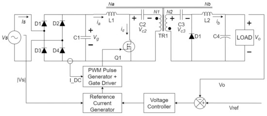
Figure 3.
Isolated PFC Cuk converter with integrated magnetics supplied by single-phase AC.
For the integrated magnetics design, a recently introduced technique proposed in [36] has been used that provides the design guidelines based on the zero-ripple conditions and magnetic model of the transformer. For reference, the reluctance model of the transformer used in the Cuk converter integrated magnetics is depicted in Figure 4. The conditions in Equations (7)–(9) must be satisfied if the input and output current ripples are zero:
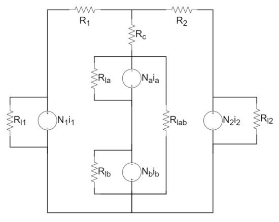
Figure 4.
Reluctance model of the transformer used in Cuk converter with integrated magnetics.
The conditions used in this technique assume that the number of turns in each winding are related as per Equations (10) and (11).
where: Number of turns in the primary side inductor, Number of turns in the secondary side inductor.
The number of turns in these coupled inductors must be greater than the number of turns of their respective sides in the transformer. In order to achieve zero ripple current, the number of turns in each winding must be related to each reluctance as described in Equations (12)–(15).
where: Total equivalent reluctance.
These conditions form the basis of design for the integrated magnetics Cuk converter with zero input and output ripple currents. In order to satisfy these equations, the primary and secondary side leakage must be high. It can also be seen from Equations (10) and (11) that the number of turns in the coupled inductors is directly dependent on the number of turns and turns ratio in the transformer. The reluctance values are selected that satisfy Equations (12)–(16). These values can then be used to find the equivalent inductance by selecting the appropriate number of turns, based on the turns of the transformer. Equation (17) presents the relationship between reluctance and its equivalent inductance:
For the design of the integrated magnetics structure, the steps for calculations based on the Cuk converter parameters are also presented. Based on the reluctance model presented in Figure 4, ref. [37] describes an analytical design methodology by deriving the equations for the ripple steering phenomenon. The conditions for zero input and output ripple currents are used to select the integrated magnetics transformer parameters.
According to the design guidelines presented in [37], the design inputs are first compiled according to the requirement. Table 5 presents the design inputs used in this converter. Standard values are taken considering the 3C94 core material and the ETD34 core size.
Table 5.
Design input parameters.
The area product of the transformer to be used in the converter is a complex function of the duty cycle and other constants. The required area product varies due to the change in duty ratio D. The worst case is considered for the design process. According to previous analysis [37], this case is obtained at . The ETD34 transformer core is selected since the core area product matches the requirement. The mean magnetic path length of this core is mentioned in Table 5.
The next step in the design methodology is to calculate the number of turns in the primary winding of the transformer, referred to as in the manuscript. The formula in Equation (18) can be used for this calculation. Here, the value of magnetizing inductance and magnetizing current is determined by the input source characteristics, while the values of and are based on the core material and size.
After the determination of , the next step is to calculate the air gap, which is given by Equation (19). The parameters and are also dependent on the core material and size. The values for ETD34 and 3C94 material are mentioned in Table 5.
Based on the above formulae, Table 6 is formulated, which consists of the output design parameters. These parameters are used to design the integrated magnetics structure for the converter.
Table 6.
Converter design parameters.
3.1.2. Current Multiplier DC-DC Control Loop
Figure 3 illustrates the schematic diagram of the converter along with the control blocks required to implement the current multiplier approach for power quality improvement. The Cuk converter is supplied by a full bridge rectifier. The switching frequency () of the Cuk converter is selected as 50 kHz. In order to improve the power quality, the input supply current should be in phase with supply voltage. The converter is operated in CCM. The PFC control scheme employs the use of the current multiplier approach with a current control loop inside the voltage control loop. The control loop calculates the voltage error (), obtained after comparing the output voltage of the converter () with the reference voltage (), which is equivalent to the rated voltage of the fan motor. A proportional–integral (PI) controller is used to give the control signal (). This signal () is multiplied with a unit reference of the input AC voltage to obtain the reference DC current () and compared with the DC current () sensed through the diode bridge rectifier. The resultant current error () is amplified and compared with a sawtooth carrier wave of fixed frequency () to generate the pulse width modulation (PWM) pulse for the Cuk converter. The duty cycle (D) of the PWM signal of switching frequency () regulates the output voltage at the setpoint (reference value). The current loop in the converter also provides over-current protection and hence prevents failure in case the fan motor is overloaded or stalled due to mechanical shortcomings, leading to a reliable design.
3.2. BLDC Motor Drive
The second main block is the BLDC motor drive. The isolated Cuk converter supplies power at constant voltage to the VSI. It is a conventional three-phase bridge with low and high side MOSFETs. The low side MOSFETs are driven directly whereas the high side MOSFETs are driven by means of a bootstrap supply. The FOC algorithm requires the current feedback from each of the three phases. The single-shunt topology is used to sense the VSI current. A single-shunt resistance which is common to all three arms of the bridge is connected to measure the current being drawn by the three phase bridge. By measuring the voltage across this shunt resistance, the phase currents are reconstructed and used by the FOC algorithm to estimate the rotor position. This voltage drop across the shunt is amplified with a non-inverting amplifier and read by the analog to digital converter (ADC) in the microcontroller running the algorithm. The shunt resistor value and amplifier gain are designed so that the maximum current flow through the bridge corresponds with the maximum current limit of the ceiling fan BLDC motor.
This single-shunt topology has been preferred over the three-shunt variant. This reduces the hardware complexity since only one shunt and one signal conditioning amplifier are required. This option is feasible if the computing power is available to perform the mathematical calculations required for phase current reconstruction. The three-shunt configuration, on the other hand, requires three shunts and three signal conditioning amplifiers, but it eliminates the need for mathematical calculations required for phase current reconstruction.
Sensorless Field Oriented Control
The speed control mechanism is an important consideration of the ceiling fan drive. The fan speed has an exponential relationship with the power consumption. In order to optimize the fan’s power consumption, the fan speed must be controlled to achieve a good compromise between the air flow produced by the fan and the power consumed. Thus, the ceiling fan drive should be able to support these variations in speed smoothly. FOC provides a speed control mechanism that can vary the fan speed smoothly even at different DC link voltages of the VSI. This is particularly useful if the VSI is supplied by a DC voltage source that is not fixed at a constant level; hence, the drive circuit can withstand variations in the DC link voltage of the VSI.
The motor is ramped up in open loop with current control until it reaches a substantial speed, and then the algorithm can be switched from open to closed loop. The final speed of the ramp is set to 30% of the maximum rotor speed and current is set to 50% of the motor nominal current. These startup parameters are experimentally tested and then refined to ensure smooth ramp up and transition to the closed loop FOC algorithm. Once the motor controller is in closed loop, the desired speed is set by providing the torque reference. This torque reference is compared with the measured value, and then the motor speed is adjusted by the FOC algorithm to match the reference torque. This reference is the main control parameter that can be set either by the IR remote control or an external Internet-connected microcontroller as illustrated in Figure 2. In order to obtain high resolution of speed steps/settings, this reference is incremented or decremented slightly and gradually depending on whether the speed needs to be increased or decreased. In order to drive the BLDC motor, the two current components at D and Q axis are controlled. In order to obtain maximum torque from the motor, the D-axis current is set to zero, whereas the Q-axis current represented by is set as per the required speed and torque.
With this method, the speed can be controlled even when the motor is powered by an alternative DC power source in case the utility electricity supply is unavailable. The VSI may also be supplied by an external DC power source such as PV panels. In this case, the DC link voltage of the inverter will not be supplied by the isolated Cuk converter. A battery or a PV panel may be used directly to supply the DC link voltage. The limitation of using these alternative sources is that the VSI will not be supplied by a constant voltage, given the intermittent nature of output voltage of a PV panel and the voltage variations of a battery based on its state of charge. These variations can effect the speed of the BLDC motor by changing the magnitude of current through the motor windings. The advantage of using FOC here is that these variations can be accounted for by observing the feedback from the VSI and adjusting the fan speed accordingly. The motor flux linkage and hence torque depend on the phase current that can be controlled by the DC link voltage and fundamental switching frequency. Therefore, a positive difference in the DC link voltage can be accounted for by introducing a negative change in the fundamental frequency and vice versa. This allows for constant speed regulation even with a supply that exhibits variations in DC voltage levels.
4. System Performance Validation
The performance of the proposed converter has been evaluated through simulation in the PLECS software. Figure 5 represents the sequential flow of power from the input to the output through the intermediate stages. Since the system is multi-rated and is operating at multiple frequencies, the frequencies in each stage have been mentioned in this figure. The highest frequency in the system is the switching frequency (50 kHz) of the Cuk converter. The simulations have been set up to verify that the output current of the power supply is indeed continuous, i.e., it contains negligible ripple at the switching frequency. Due to this negligible high frequency ripple, it can be verified that the stator currents and hence motor torque ripple also do not exhibit significant frequency components at the DC-DC converter switching frequency.
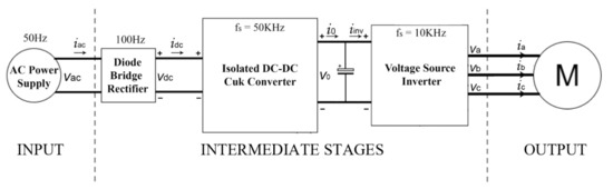
Figure 5.
System diagram highlighting the various frequencies of operation in all the stages.
The simulation results have been presented as follows in a sequential manner. The input characteristics (voltage and current) have been presented first. Next, the intermediate stage characteristics have been presented by showing the waveforms of the currents in the coils and switch stresses in the DC-DC converter. The Cuk converter’s terminal voltage and current have also been shown. Afterwards, the output characteristics have been illustrated by presenting the BLDC motor drive operation and torque ripple. Lastly, the system failure mode simulations have been presented.
- 1.
- Input Characteristics (Voltage and Current): Figure 6 presents a steady state simulation of the converter in time domain. The input voltage and current from the single-phase AC supply are shown. It can be visualized that the PFC implementation using the multiplier method shapes the current waveform to follow the input voltage . The sinusoidal current shows that the BLDC fan emulates a resistive load.
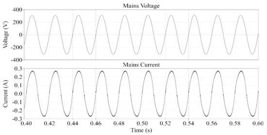 Figure 6. Steady state time domain simulation of the converter depicting the input voltage and current .Figure 7 presents the input voltage and current waveforms in the frequency domain to visualize the supply current harmonics. Since the supply voltage is selected as 220 V AC at 50 Hz, the fundamental frequency of the current is also 50 Hz. It can be observed that the signal magnitude peaks at 50 Hz and the harmonic contents are low around this frequency. Small magnitudes of odd harmonics at can also be observed.
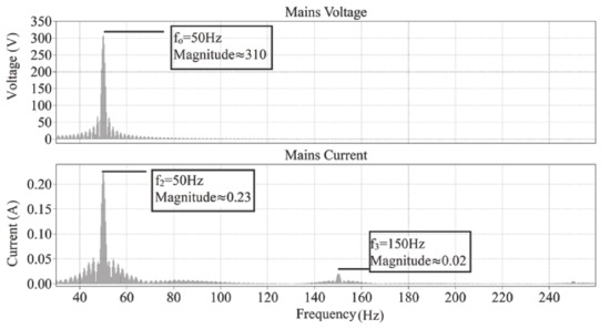 Figure 7. Steady state frequency domain simulation of the converter depicting the input voltage and current showing the low frequency components.Figure 8 presents the input voltage and current waveforms in the frequency domain to visualize the supply current harmonics at the switching frequency of 50 kHz. The relative logarithmic scale (dB) has been used for clear visualization. It can be observed that the signal contains a small ripple at 50 kHz due to the switching of the MOSFET.
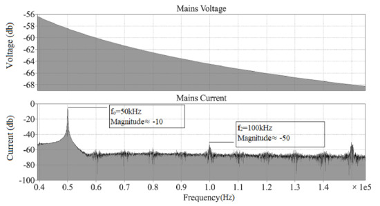 Figure 8. Steady state frequency domain simulation of the converter depicting the input voltage and current showing the high frequency components.
 - 2.
- Intermediate Stage Characteristics (DC-DC Converter Operation): The waveforms of the high voltage input side and low voltage output side of the DC-DC converter have been presented separately. Figure 9 presents the input side parameters, namely the duty ratio D, input inductor current , MOSFET drain to source voltage , and its drain current . The MOSFET duty ratio D is responsible for current shaping in the converter. The fundamental frequency here is 100 Hz, which follows the output of the full bridge rectifier, as a result of the current multiplier method for PFC implementation. This frequency is reflected in all of the input and output waveforms. The input inductor current is continuous and shows a small ripple at the switching frequency of 50 kHz. The same switching frequency can be seen in the MOSFET drain to source voltage and the MOSFET drain current .
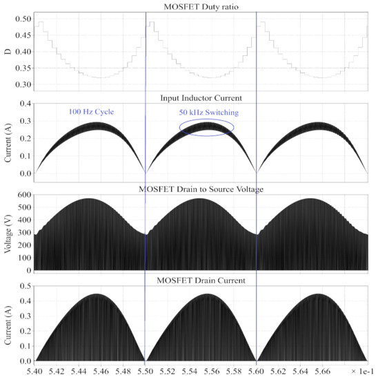 Figure 9. Waveforms in the input side of the DC-DC converter. MOSFET duty ratio D, input inductor current , MOSFET drain to source voltage , and MOSFET drain current .Similarly, the waveforms in Figure 10 below present the voltage and currents in the low voltage output side. The diode is forward biased for the period when the MOSFET is switched off, and vice versa. The same 100 Hz fundamental frequency can be visualized in the output side waveforms as well. The output inductor current is also continuous and exhibits nearly zero ripple at the switching frequency.
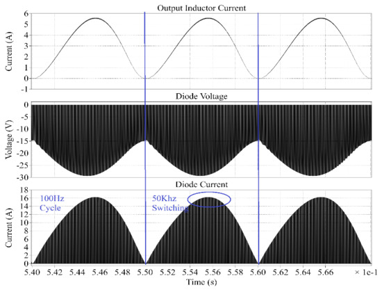 Figure 10. Waveforms in the output side of the DC-DC converter: output inductor current , diode voltage , and diode current .Figure 11 presents the output voltage and output inductor current of the proposed converter. Initially, the current magnitude is high because the DC link capacitor needs to be charged. When the output voltage becomes stable at 15 V, the motor ramps up and reaches steady state. It can be noted, however, that the output voltage increases slightly in the time range 0.14–0.22 s. This increase is due to the initial overshoot of the converter’s control system. After this slight overshoot, the output voltage settles at 15 V, which is the reference setpoint of the output voltage. The current magnitude is constant when this steady state is reached. It can be noted, however, that the output inductor current oscillates at 100 Hz, due to the absence of a DC bulk capacitor at the output terminals of the diode bridge rectifier. This is an inherent characteristic of the PFC technique used [38]. Since the FOC loop of the sensorless BLDC motor control operates at 10 kHz, this low frequency oscillation does not cause significant ripple in either the stator currents or the motor torque .
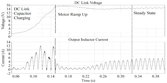 Figure 11. Time domain simulation of the converter depicting the output voltage and output inductor current .Figure 12 presents the output voltage and output inductor current waveforms in the frequency domain (dB scale) to visualize the 100 Hz harmonics. As discussed earlier, the 100 Hz ripple is visible in both the output voltage and inductor current .
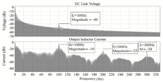 Figure 12. Frequency domain simulation of the converter depicting the output voltage and output inductor current low frequency components.Figure 13 presents the output voltage and output inductor current harmonics (dB scale) at the converter switching frequency of 50 kHz. The harmonic content due to the small switching ripple is observed.
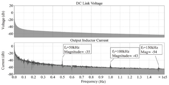 Figure 13. Frequency domain simulation of the converter depicting the output voltage and output inductor current high frequency components.
 - 3.
- Output Characteristics (Motor Torque Ripple): Figure 14 presents the motor stator currents and torque in the time domain. The motor speed and torque ramp up and reach steady state as seen in the figure. The steady state speed is achieved when the fundamental frequency of the VSI is 38 Hz.
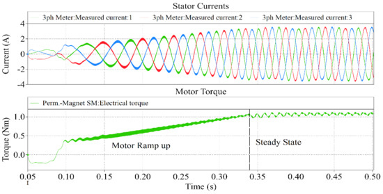 Figure 14. Time domain simulation depicting the motor stator currents and torque .The motor stator currents and torque in the frequency domain are presented in Figure 15. The 38 Hz frequency component can be clearly seen in the frequency spectrum. Furthermore, the frequency components of the motor torque also indicate that there is a small ripple caused by both the fundamental frequency of the VSI (38 Hz) and the output inductor current (100 Hz).
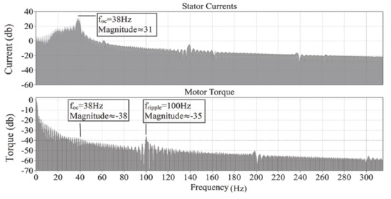 Figure 15. Frequency domain simulation depicting the low frequency components of the stator currents and motor torque .The high frequency components of the stator currents and motor torque are presented in Figure 16.
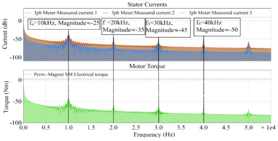 Figure 16. Frequency domain simulation depicting the high frequency components of the stator currents and motor torque .
 - 4.
- System Failure Modes: Two failure modes have been modeled to demonstrate the reliability of the power supply design. The first case demonstrates an over-current fault that may be caused by a physical fault in the motor. The second case demonstrates a failure mode in which the inverter stops operating due to component failure. The simulation in Figure 17 demonstrates the first failure mode in which the motor winding is shorted. The input inductor current and output DC link voltage are presented. This particular fault causes an over-current condition, which is modeled in this simulation with a resistive load that is connected at the output of the power supply at time ‘t’ as marked in the figure. This additional load causes the output current to increase. The input current also increases proportionally, which is sensed by the same current sensing shunt resistor that is used to implement the PFC loop. As soon as the threshold (0.45 A in this example) is crossed, the over-current protection comparator is triggered, and the duty cycle D of the MOSFET is decreased to reduce the flow of current in the circuit. The simulation shows that the fault state causes an increase in input current , which is compensated by the PFC control loop in one single switching cycle. As a result of this current limiting protection feature, the DC link voltage also decreases sharply.
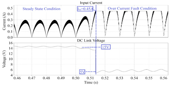 Figure 17. Transient simulation of over-current fault protection in the power supply, showing the input current and DC link voltage .The simulation in Figure 18 presents the second fault that shows the inverter failure mode. The graph shows the inverter ON/OFF state, stator currents , motor torque , output DC link voltage , and the power supply current . The fault is modeled by removing all the gate pulses to the MOSFETs of the VSI, which effectively shuts down the inverter. It can be observed that the inverter shut down causes the motor to temporarily act as a generator. The supply current direction is reversed, and the motor torque and stator currents decrease to zero. The DC link capacitor is charged, which causes the DC link voltage to increase. Overall, this fault is tolerated by the power supply.
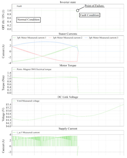 Figure 18. Transient simulation of inverter failure fault, showing the inverter state, stator currents , motor torque , DC link voltage , and supply current .
5. Results and Discussion
In the light of the simulations obtained through the PLECS software presented in the previous section, the effect of the switching frequency of the VSI (10 kHz) can be observed in Figure 16 in the stator currents and motor torque ripple. The harmonics of this switching ripple can also be visualized in the figure. The result shows that the DC-DC converter switching frequency (50 kHz) ripple does not cause any significant motor torque ripple. In a conventional design, however, this switching frequency ripple would have affected the stator currents , and the same would have also been reflected in the motor torque . Therefore, it can be concluded that the proposed power supply design is suitable for BLDC fan motors, as there are negligible motor torque ripples.
In view of the failure modes analysis presented in the above section, the power supply tolerates over-current faults by limiting the input current of the converter, as seen in Figure 17. The value of the MOSFET duty cycle D is updated at the switching frequency = 50 kHz according to the current and voltage feedback. Therefore, in the case of an over-current event, the response time of the loop will be one switching interval of the DC-DC converter. In this case, = 20 s. As a result of this current limiting protection feature, the DC link voltage also decreases sharply. Moreover, as shown in Figure 18, the converter also tolerates inverter failure without causing any damage. Therefore, it can be concluded that the two common faults discussed in this paper do not negatively affect the system, making it reliable.
The input power quality of the converter is in line with the requirements specified in Table 4. The PF is found to be 0.99 whereas the THD is measured as 4.72% as per the simulation at rated load. The power quality indices of the other topologies (buck–boost, SEPIC, Zeta) implemented with their own PFC techniques that have been reported in the literature in [27,28,29] have also been compared with the simulation results of the proposed design. Figure 19 represents the comparison of the four designs. The data of the proposed design have been obtained through simulation, while the data of the other three designs have been taken from the previously reported work in the literature [27,28,29]. Since every fan motor is designed to operate for different specifications, it is inappropriate to compare the power quality parameters as a function of the fan speed. Therefore, the PF and THD have been plotted as a function of the real power supplied by the AC-DC supply. This can be used to evaluate their performance and compare these designs. It can be inferred from Figure 19 that all four converters exhibit similar performance with minor differences. All these designs comply with existing standards, exhibiting near-unity PF and low THD in all operating conditions. Therefore, it can be concluded that the proposed CCM Cuk converter provides the abovementioned advantages with no compromise on input power quality.
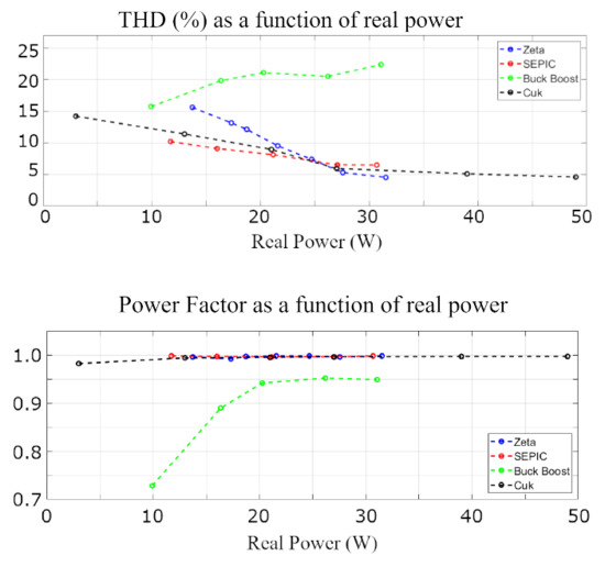
Figure 19.
Comparisons of power factor and total harmonic distortion between the proposed design and other supply topologies.
Table 7 below describes the indicative cost of the major components required in each of the four converters. The table shows the quantity and description of each of the components required. Since quantification of the cost is a subjective topic having dependencies on several design choices, the cost of each component has been discussed qualitatively. Intuitively, it may seem that the Cuk converter is an expensive option due to overall higher component count, but the integrated magnetics and highly efficient transformer design are cost effective since they deliver the same power with smaller sized magnetics.
Table 7.
Indicative cost comparison table of the isolated buck–boost converters.
By inspection of the component count and type, it can be seen that the Flyback converter is the cheapest option, despite its inefficient and bigger transformer, which explains its commercial success. The proposed Cuk converter with integrated magnetics ranks second, while the SEPIC and Zeta converters follow behind. Such trade-offs between cost and performance always exist in most designs. The proposed converter offers an optimized choice between cost and performance.
6. Conclusions
The isolated PFC Cuk converter with integrated magnetics is found to be a suitable option to power BLDC ceiling fans. The frequency components of all the results have also been presented to highlight the effects of switching in various parts of the system. Simulation results from PLECS have been presented to validate the system design on a 15 V BLDC ceiling fan, which are generally very similar to the experimental hardware results. Using the results described in this paper, experimental design including the magnetic assembly and design optimization can be conducted as a future prospect of this work. In addition to ceiling fans, this design can be implemented in other applications where low-power BLDC motors are supplied by a single-phase AC power source, such as home appliances and small power tools. This system can also be integrated with IoT-based controllers to design smart products that may be used in the future to serve the purposes of autonomous control and power consumption optimization.
Author Contributions
Conceptualization, H.R.K. and S.A.Q.; methodology, H.R.K., H.B.A., and M.H.B.K.; software, H.B.A. and M.H.B.K.; validation, H.R.K., M.K., and S.A.Q.; formal analysis, H.B.A., M.K., and M.H.B.K.; investigation, M.K. and H.B.A.; resources, A.H. and S.A.Q.; data curation, H.B.A., M.H.B.K., and A.H.; writing—original draft preparation, H.B.A.; writing—review and editing, M.K. and S.A.Q.; visualization, H.R.K., M.K., H.B.A., M.H.B.K., and A.H.; supervision, H.R.K.; project administration, S.A.Q.; funding acquisition, S.A.Q. All authors have read and agreed to the published version of the manuscript.
Funding
This work is funded by Neuro-computation Lab, National Center of Artificial Intelligence, NED University of Engineering and Technology, Pakistan.
Data Availability Statement
The data presented in this study are available in this article.
Conflicts of Interest
The authors declare no conflict of interest. The funders had no role in the design of the study; in the collection, analyses, or interpretation of data; in the writing of the manuscript; or in the decision to publish the results.
Appendix A
Table A1.
List of acronyms.
Table A1.
List of acronyms.
| Acronym | Full Term |
|---|---|
| ADC | Analog to Digital Converter |
| CCM | Continuous Conduction Mode |
| CRT | Cathode Ray Tube |
| DCM | Discontinuous Conduction Mode |
| EMF | Electro Motive Force |
| FOC | Field Oriented Control |
| PF | Power Factor |
| PFC | Power Factor Correction |
| PLECS | Piecewise Linear Electrical Circuit Simulation |
| PMSM | Permanent Magnet Synchronous Motor |
| PV | Photo-Voltaic |
| PWM | Pulse Width Modulation |
| SEPIC | Single Ended Primary Inductance Converter |
| THD | Total Harmonic Distortion |
| VSI | Voltage Source Inverter |
Table A2.
List of notations and their units.
Table A2.
List of notations and their units.
| Notation | Full Term | Unit |
|---|---|---|
| Output voltage | V | |
| D | Duty ratio | - |
| Number of turns in transformer primary winding | - | |
| Number of turns in transformer secondary winding | - | |
| Input voltage | V | |
| Switching frequency | Hz | |
| Current ripple in inductor 1 | A | |
| Current ripple in inductor 2 | A | |
| R | Equivalent load resistance | Ohms |
| Voltage ripple across capacitor 2 | V | |
| Voltage ripple across capacitor 3 | V | |
| Number of turns in the primary side inductor | - | |
| Number of turns in the secondary side inductor | - | |
| Total equivalent reluctance | AT/Web | |
| Voltage error | V | |
| Reference voltage | V | |
| D-axis current | A | |
| Q-axis current | A |
Table A3.
Parameters of the BLDC ceiling fan motor.
Table A3.
Parameters of the BLDC ceiling fan motor.
| Parameter | Value |
|---|---|
| No. of rotor poles | 14 |
| Voltage rating | 15 V |
| Rated speed | 340 RPM |
| Rated torque | 1.1 Nm |
| Back-EMF constant | 31 Vrms/krpm |
| Resistance of winding (per phase) | 0.55 Ohms |
| Inductance of winding (per phase) | 0.72 mH |
References
- Garg, A.; Maheshwari, J.; Mukherjee, D. Transitions towards energy-efficient appliances in urban households of gujarat state, india. Int. J. Sustain. Energy 2020, 40, 638–653. [Google Scholar] [CrossRef]
- Parikh, K.S.; Parikh, J.K. Realizing potential savings of energy and emissions from efficient household appliances in india. Energy Policy 2016, 97, 102–111. [Google Scholar] [CrossRef]
- Hanselman, D. Brushless Motors: Magnetic Design, Performance, and Control of Brushless DC and Permanent Magnet Synchronous Motors; E-Man Press LLC: New York, NY, USA, 2012. [Google Scholar]
- Patel, H.; Nagarsheth, R.; Parnerkar, S. Performance comparison of permanent magnet synchronous motor and induction motor for cooling tower application. Int. J. Emerg. Technol. Adv. Eng. 2012, 2, 167–171. [Google Scholar]
- Shah, N.; Sathaye, N.; Phadke, A.; Letschert, V. Efficiency improvement opportunities for ceiling fans. Energy Effic. 2015, 8, 37–50. [Google Scholar] [CrossRef] [Green Version]
- Liu, C.-S.; Hwang, J.-C.; Chen, P.-C. Permanent magnet synchronous motor for ceiling fan. In Proceedings of the 2010 IEEE International Conference on Sustainable Energy Technologies (ICSET), Kandy, Sri Lanka, 6–9 December 2010; pp. 1–4. [Google Scholar]
- Sakunthala, S.; Kiranmayi, R.; Mandadi, P.N. A study on industrial motor drives: Comparison and applications of pmsm and BLDC motor drives. In Proceedings of the 2017 International Conference on Energy, Communication, Data Analytics and Soft Computing (ICECDS), Chennai, India, 1–2 August 2017; pp. 537–540. [Google Scholar]
- Hendershot, J.R., Jr.; Miller, T. Design of Brushless Permanent Magnet Motor, 1st ed.; Clarendon Press/Magna Physics Publishing: Oxford, UK, 1994. [Google Scholar]
- Pillay, P.; Krishnan, R. Modeling, simulation, and analysis of permanent-magnet motor drives. II. The brushless DC motor drive. IEEE Trans. Ind. Appl. 1989, 25, 274–279. [Google Scholar] [CrossRef]
- Zhu, Z.; Wu, L.; Jamil, M.M. Distortion of back-EMF and torque of PM brushless machines due to eccentricity. IEEE Trans. Magn. 2013, 49, 4927–4936. [Google Scholar] [CrossRef]
- Carlson, R.; Tavares, A.A.; Bastos, J.P.; Lajoie-Mazenc, M. Torque ripple attenuation in permanent magnet synchronous motors. In Proceedings of the Conference Record of the IEEE Industry Applications Society Annual Meeting, San Diego, CA, USA, 1–5 October 1989; pp. 57–62. [Google Scholar]
- England, T.R. Unique surface-wound brushless servo with improved torque ripple characteristics. IEEE Trans. Ind. Appl. 1988, 24, 972–977. [Google Scholar] [CrossRef]
- Kim, D.; Lee, K.-W.; Kwon, B.-I. Commutation torque ripple reduction in a position sensorless brushless DC motor drive. IEEE Trans. Power Electron. 2006, 21, 1762–1768. [Google Scholar] [CrossRef]
- Mohamed, Y.A.-R.I.; El-Saadany, E.F. A current control scheme with an adaptive internal model for robust current regulation and torque ripple minimization in PMSM vector drive. In Proceedings of the 2007 IEEE International Electric Machines & Drives Conference, Antalya, Turkey, 3–5 May 2007; Volume 1, pp. 300–305. [Google Scholar]
- Tewari, S.V.; Rani, B.I. Torque ripple minimization of BLDC motor with un-ideal back EMF. In Proceedings of the 2009 Second International Conference on Emerging Trends in Engineering & Technology, Nagpur, India, 16–18 December 2009; pp. 687–690. [Google Scholar]
- Zhang, H.L.; Qu, L.W. A new torque control method for torque ripple minimization of BLDC motors with un-ideal back EMF. IEEE Trans. Power Electron. 2008, 23, 950–958. [Google Scholar]
- Nam, K.-Y.; Lee, W.-T.; Lee, C.-M.; Hong, J.-P. Reducing torque ripple of brushless DC motor by varying input voltage. IEEE Trans. Magn. 2006, 42, 1307–1310. [Google Scholar]
- Berendsen, C.-S.; Champenois, G.; Bolopion, A. Commutation strategies for brushless DC motors: Influence on instant torque. IEEE Trans. Power Electron. 1993, 8, 231–236. [Google Scholar] [CrossRef]
- Ozturk, S.B.; Alexander, W.C.; Toliyat, H.A. Direct torque control of four-switch brushless DC motor with non-sinusoidal back EMF. IEEE Trans. Power Electron. 2010, 25, 263–271. [Google Scholar] [CrossRef]
- Zhang, Y.; Zhu, J.; Xu, W.; Guo, Y. A simple method to reduce torque ripple in direct torque-controlled permanent-magnet synchronous motor by using vectors with variable amplitude and angle. IEEE Trans. Ind. Electron. 2011, 58, 2848–2859. [Google Scholar] [CrossRef] [Green Version]
- IEC 61000-3-2. Limits—Limits for Harmonic Current Emissions; International Electrotechnical Commission: London, UK, 2018. [Google Scholar]
- Singh, B.; Singh, S.; Chandra, A.; Al-Haddad, K. Comprehensive study of single-phase ac-dc power factor corrected converters with high-frequency isolation. IEEE Trans. Ind. Inform. 2011, 7, 540–556. [Google Scholar] [CrossRef]
- Bist, V.; Singh, B. A brushless dc motor drive with power factor correction using isolated zeta converter. IEEE Trans. Ind. Inform. 2014, 10, 2064–2072. [Google Scholar] [CrossRef]
- Bist, V.; Singh, B. Pfc cuk converter-fed BLDC motor drive. IEEE Trans. Power Electron. 2014, 30, 871–887. [Google Scholar] [CrossRef]
- Bist, V.; Singh, B. A unity power factor bridgeless isolated cuk converter-fed brushless dc motor drive. IEEE Trans. Ind. Electron. 2014, 62, 4118–4129. [Google Scholar] [CrossRef]
- Singh, P.K.; Singh, B.; Bist, V. Brushless dc motor drive with power factor regulation using landsman converter. IET Power Electron. 2016, 9, 900–910. [Google Scholar] [CrossRef]
- Manglik, S.; Sundeep, S.; Singh, B. Brushless dc motor based ceiling fan using buck-boost converter. In Proceedings of the 2016 IEEE 7th Power India International Conference (PIICON), Bikaner, India, 25–27 November 2016; pp. 1–6. [Google Scholar]
- Kumar, A.; Sharma, U.; Singh, B. Pmbldc motor based ceiling fan using an isolated pfc zeta converter. In Proceedings of the 2020 IEEE International Conference on Power Electronics, Smart Grid and Renewable Energy (PESGRE2020), Cochin, India, 2–4 January 2020; pp. 1–6. [Google Scholar]
- Kumar, A.; Sharma, U.; Singh, B. Bldc motor ceiling fan using a bridgeless isolated pfc sepic converter. In Proceedings of the 2020 IEEE 9th Power India International Conference (PIICON), Sonepat, India, 28 February–1 March 2020; pp. 1–6. [Google Scholar]
- Amirkhanian, H.; Oknaian, S. Power loss breakdown in bldc drives applications using matlab. In Proceedings of the International Exhibition and Conference for Power Electronics, Intelligent Motion, Renewable Energy and Energy Management, Nuremberg, Germany, 5–7 June 2018; pp. 1–5. [Google Scholar]
- Infineon Technologies AG. Block Commutation vs. Foc in Power Tool Motor Control. Available online: https://www.infineon.com/dgdl/Infineon-Motor_power_tool_Block_Commutation_vs_FOC-ApplicationNotes-v01_00-EN.pdf?fileId=5546d4626eab8fbf016ed37fee474a65 (accessed on 4 January 2021).
- Sasaki, H.; Asai, K.; Gohara, Y.; Moroizumi, M. Motor Control Circuit and Fan Including the Same. U.S. Patent 10,003,288, 19 June 2018. [Google Scholar]
- Huang, L.-Q.; Chang, Y.-C.; Liu, Y.-G.; Liang, Z.-J. Ceiling Fan, Method for Controlling Ceiling Fan Motor and Control Device for Ceiling Fan Motor. U.S. Patent 10,374,536, 6 August 2019. [Google Scholar]
- Rissetto, R.; Schweiker, M.; Wagner, A. Personalized ceiling fans: Effects of air motion, air direction and personal control on thermal comfort. Energy Build. 2021, 235, 110721. [Google Scholar] [CrossRef]
- Williams, B.W. Transformer isolated buck-boost converters. Renew. Energy Sustain. Dev. 2016, 2, 112–125. [Google Scholar] [CrossRef]
- Ramanath, A.; Kshirsagar, A.; Thamballa, S.; Mohan, N. Equivalent Modeling, Design and Analysis of Integrated Magnetics Ćuk Converter. In Proceedings of the 2019 North American Power Symposium (NAPS), Wichita, KS, USA, 13–15 October 2019. [Google Scholar]
- Biswas, S.; Mohan, N.; Robbins, W. A systematic design method and verification for a zero-ripple interface for PV/Battery-to-grid applications. In Proceedings of the 2016 IEEE Applied Power Electronics Conference and Exposition (APEC), Long Beach, CA, USA, 20–24 March 2016. [Google Scholar]
- Singh, S.; Singh, B. A voltage-controlled pfc cuk converter-based pmbldcm drive for air-conditioners. IEEE Trans. Ind. Appl. 2012, 48, 832–838. [Google Scholar] [CrossRef]
Publisher’s Note: MDPI stays neutral with regard to jurisdictional claims in published maps and institutional affiliations. |
© 2021 by the authors. Licensee MDPI, Basel, Switzerland. This article is an open access article distributed under the terms and conditions of the Creative Commons Attribution (CC BY) license (https://creativecommons.org/licenses/by/4.0/).