
An Isolated Power Factor Corrected Cuk Converter with Integrated Magnetics for Brushless DC Ceiling Fan Applications


Abstract
:1. Introduction
- 1.
- Power supply design with negligible ripples: Presenting the design methodology for the development of an isolated PFC Cuk converter with integrated magnetics for low-power applications. This enables a design that is compact, efficient, and provides stable power supply with nearly zero high frequency ripples.
- 2.
- BLDC fan operation with low torque ripple: Using the Cuk converter to incorporate continuous input and output currents in the AC-DC supply design. This minimizes the current ripples and ensures less torque ripple in the BLDC fan motor.
- 3.
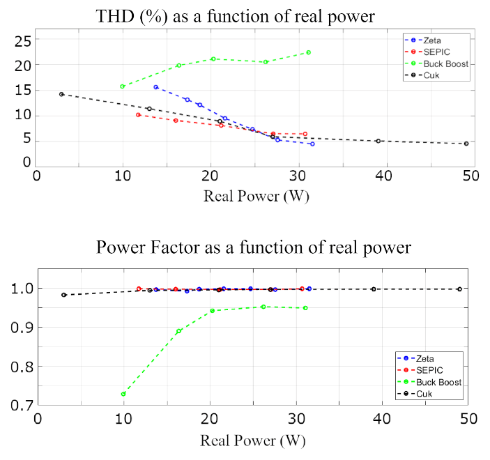
- IEC standards compliance: Deploying the isolated Cuk converter in continuous conduction mode (CCM) with the current multiplier technique. This enables power factor correction (PFC) and a total harmonic distortion (THD) reduction along with an additional feature of over-current protection.
- 4.
- Failure modes analysis: A comprehensive analysis with common fault conditions of the ceiling fan and their impact on the proposed power supply is presented.
2. Background
3. Methodology
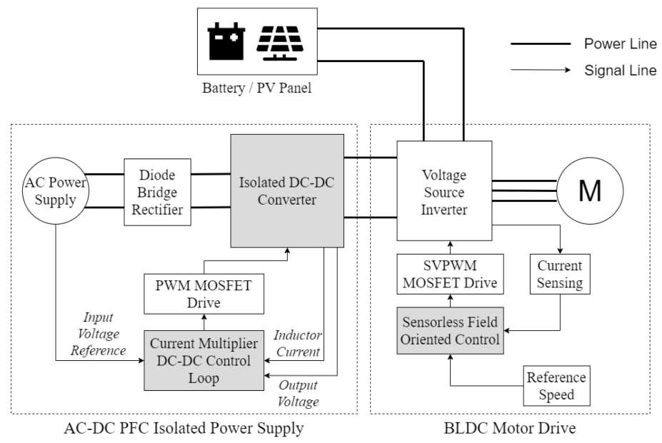
3.1. AC-DC PFC Isolated Power Supply
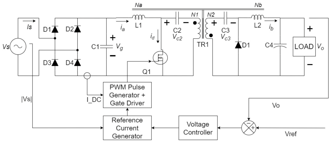
3.1.1. Isolated DC-DC Converter
3.1.2. Current Multiplier DC-DC Control Loop
3.2. BLDC Motor Drive
Sensorless Field Oriented Control
4. System Performance Validation
- 1.
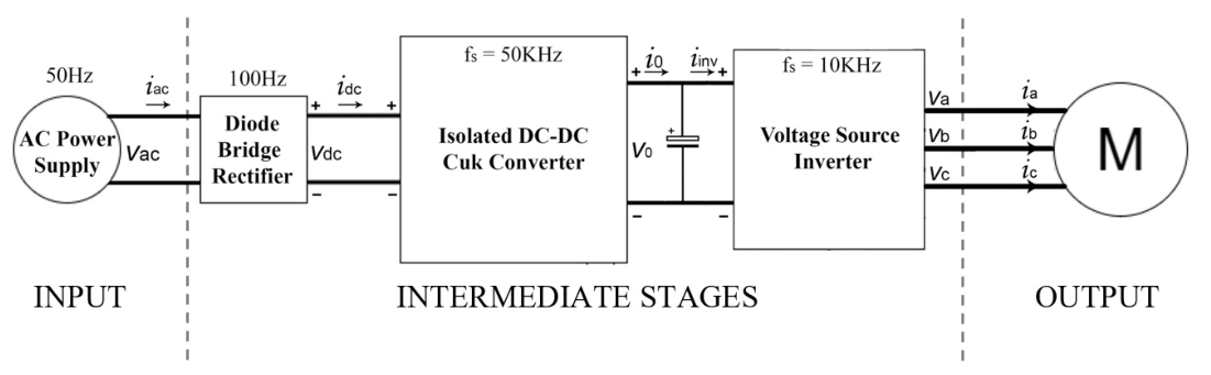
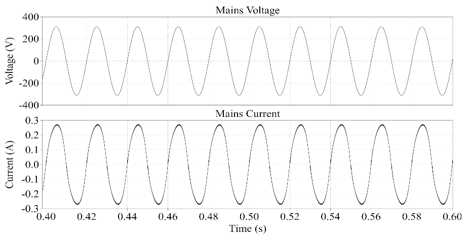
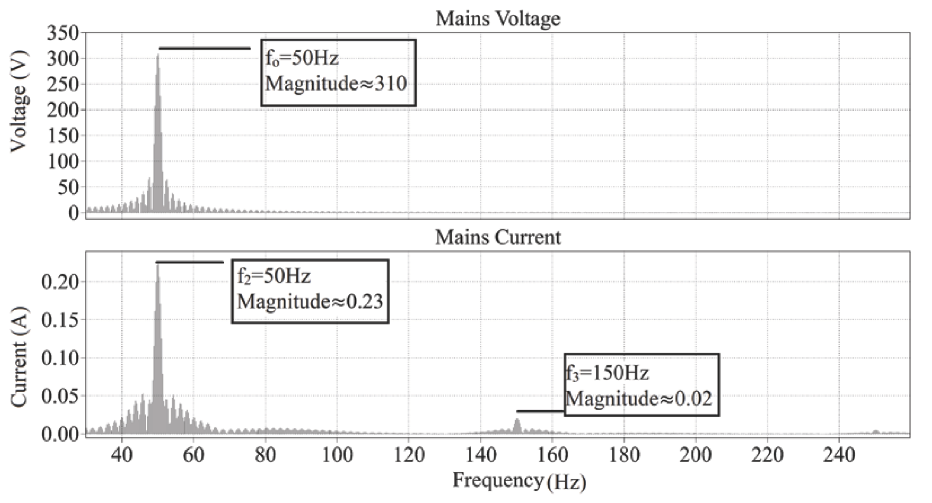
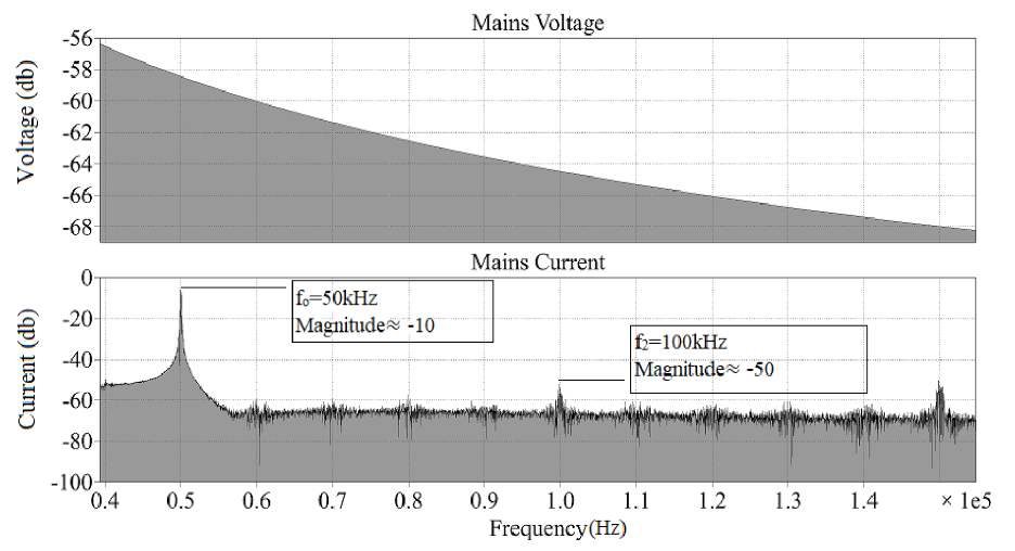
- Input Characteristics (Voltage and Current): Figure 6 presents a steady state simulation of the converter in time domain. The input voltage and current from the single-phase AC supply are shown. It can be visualized that the PFC implementation using the multiplier method shapes the current waveform to follow the input voltage . The sinusoidal current shows that the BLDC fan emulates a resistive load.Figure 7 presents the input voltage and current waveforms in the frequency domain to visualize the supply current harmonics. Since the supply voltage is selected as 220 V AC at 50 Hz, the fundamental frequency of the current is also 50 Hz. It can be observed that the signal magnitude peaks at 50 Hz and the harmonic contents are low around this frequency. Small magnitudes of odd harmonics at can also be observed.Figure 8 presents the input voltage and current waveforms in the frequency domain to visualize the supply current harmonics at the switching frequency of 50 kHz. The relative logarithmic scale (dB) has been used for clear visualization. It can be observed that the signal contains a small ripple at 50 kHz due to the switching of the MOSFET.
- 2.
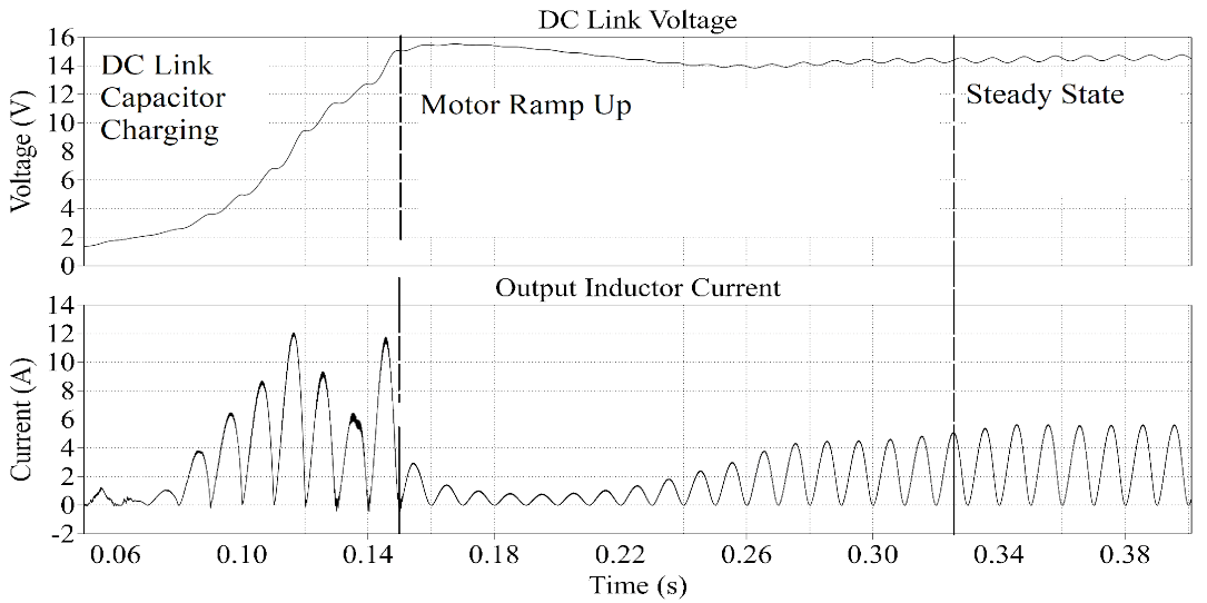
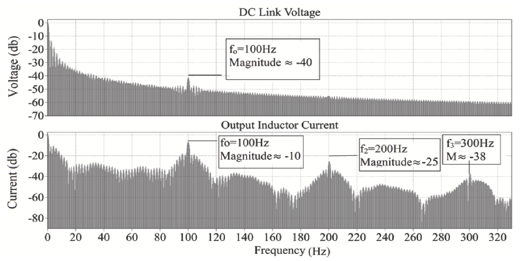
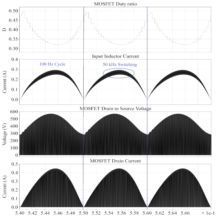
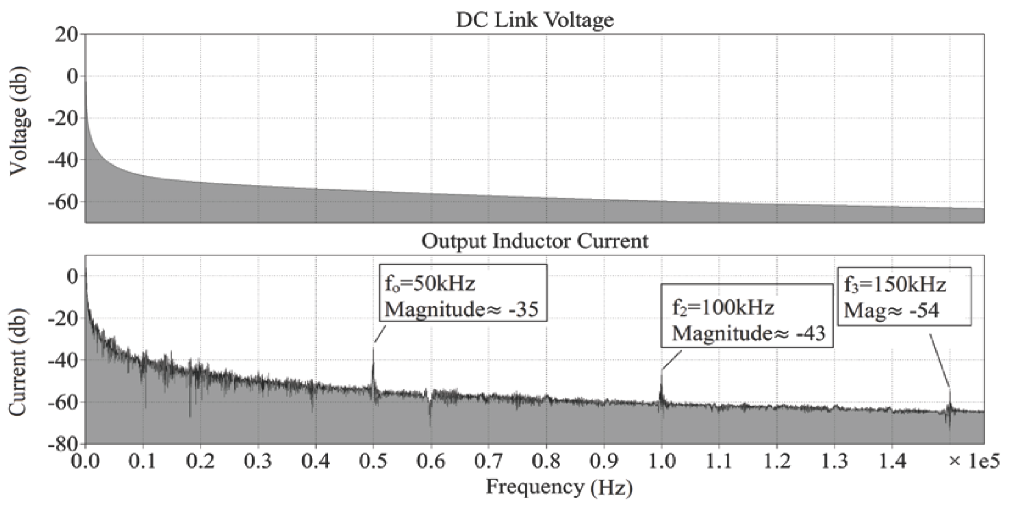
- Intermediate Stage Characteristics (DC-DC Converter Operation): The waveforms of the high voltage input side and low voltage output side of the DC-DC converter have been presented separately. Figure 9 presents the input side parameters, namely the duty ratio D, input inductor current , MOSFET drain to source voltage , and its drain current . The MOSFET duty ratio D is responsible for current shaping in the converter. The fundamental frequency here is 100 Hz, which follows the output of the full bridge rectifier, as a result of the current multiplier method for PFC implementation. This frequency is reflected in all of the input and output waveforms. The input inductor current is continuous and shows a small ripple at the switching frequency of 50 kHz. The same switching frequency can be seen in the MOSFET drain to source voltage and the MOSFET drain current .Similarly, the waveforms in Figure 10 below present the voltage and currents in the low voltage output side. The diode is forward biased for the period when the MOSFET is switched off, and vice versa. The same 100 Hz fundamental frequency can be visualized in the output side waveforms as well. The output inductor current is also continuous and exhibits nearly zero ripple at the switching frequency.Figure 11 presents the output voltage and output inductor current of the proposed converter. Initially, the current magnitude is high because the DC link capacitor needs to be charged. When the output voltage becomes stable at 15 V, the motor ramps up and reaches steady state. It can be noted, however, that the output voltage increases slightly in the time range 0.14–0.22 s. This increase is due to the initial overshoot of the converter’s control system. After this slight overshoot, the output voltage settles at 15 V, which is the reference setpoint of the output voltage. The current magnitude is constant when this steady state is reached. It can be noted, however, that the output inductor current oscillates at 100 Hz, due to the absence of a DC bulk capacitor at the output terminals of the diode bridge rectifier. This is an inherent characteristic of the PFC technique used [38]. Since the FOC loop of the sensorless BLDC motor control operates at 10 kHz, this low frequency oscillation does not cause significant ripple in either the stator currents or the motor torque .Figure 12 presents the output voltage and output inductor current waveforms in the frequency domain (dB scale) to visualize the 100 Hz harmonics. As discussed earlier, the 100 Hz ripple is visible in both the output voltage and inductor current .Figure 13 presents the output voltage and output inductor current harmonics (dB scale) at the converter switching frequency of 50 kHz. The harmonic content due to the small switching ripple is observed.
- 3.
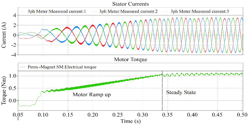
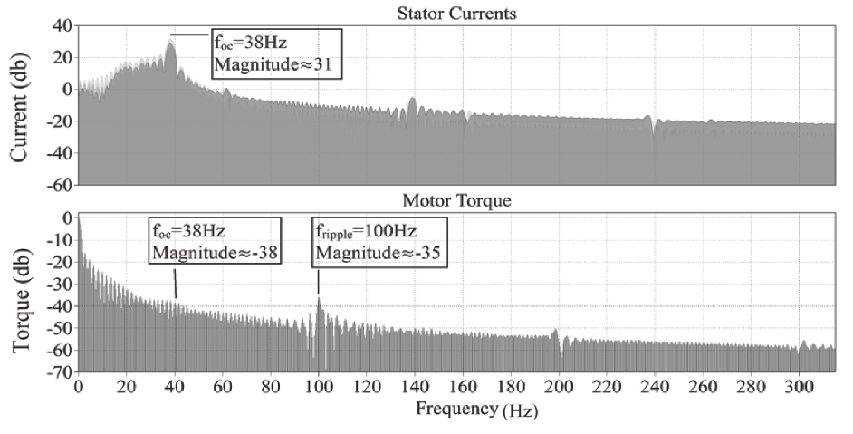
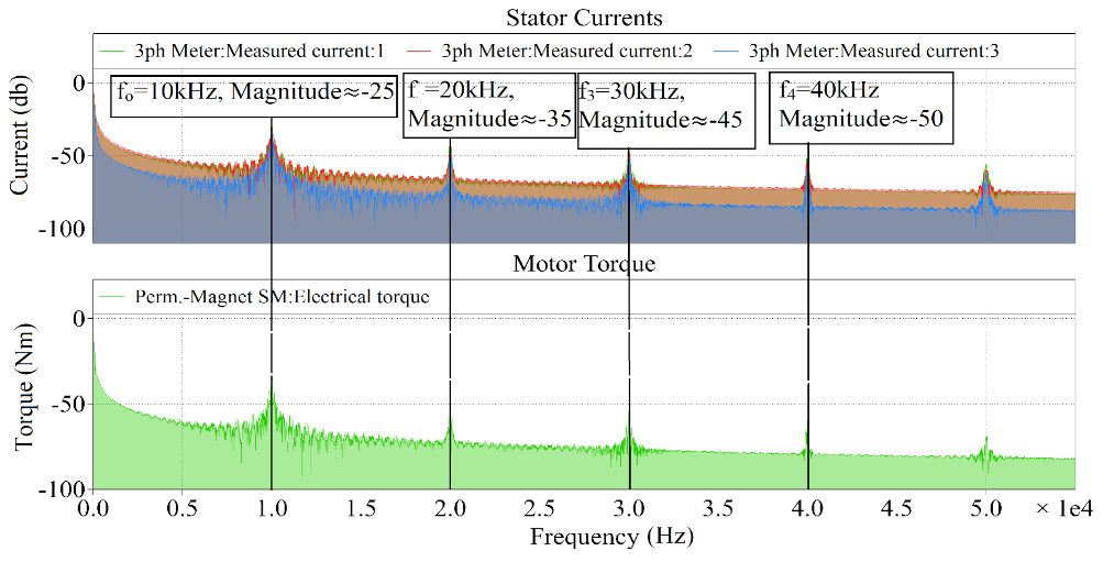
- Output Characteristics (Motor Torque Ripple): Figure 14 presents the motor stator currents and torque in the time domain. The motor speed and torque ramp up and reach steady state as seen in the figure. The steady state speed is achieved when the fundamental frequency of the VSI is 38 Hz.The motor stator currents and torque in the frequency domain are presented in Figure 15. The 38 Hz frequency component can be clearly seen in the frequency spectrum. Furthermore, the frequency components of the motor torque also indicate that there is a small ripple caused by both the fundamental frequency of the VSI (38 Hz) and the output inductor current (100 Hz).The high frequency components of the stator currents and motor torque are presented in Figure 16.
- 4.
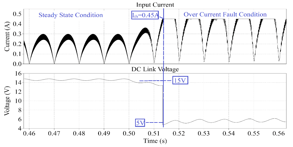
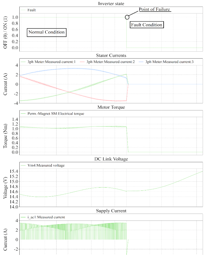
- System Failure Modes: Two failure modes have been modeled to demonstrate the reliability of the power supply design. The first case demonstrates an over-current fault that may be caused by a physical fault in the motor. The second case demonstrates a failure mode in which the inverter stops operating due to component failure. The simulation in Figure 17 demonstrates the first failure mode in which the motor winding is shorted. The input inductor current and output DC link voltage are presented. This particular fault causes an over-current condition, which is modeled in this simulation with a resistive load that is connected at the output of the power supply at time ‘t’ as marked in the figure. This additional load causes the output current to increase. The input current also increases proportionally, which is sensed by the same current sensing shunt resistor that is used to implement the PFC loop. As soon as the threshold (0.45 A in this example) is crossed, the over-current protection comparator is triggered, and the duty cycle D of the MOSFET is decreased to reduce the flow of current in the circuit. The simulation shows that the fault state causes an increase in input current , which is compensated by the PFC control loop in one single switching cycle. As a result of this current limiting protection feature, the DC link voltage also decreases sharply.The simulation in Figure 18 presents the second fault that shows the inverter failure mode. The graph shows the inverter ON/OFF state, stator currents , motor torque , output DC link voltage , and the power supply current . The fault is modeled by removing all the gate pulses to the MOSFETs of the VSI, which effectively shuts down the inverter. It can be observed that the inverter shut down causes the motor to temporarily act as a generator. The supply current direction is reversed, and the motor torque and stator currents decrease to zero. The DC link capacitor is charged, which causes the DC link voltage to increase. Overall, this fault is tolerated by the power supply.
5. Results and Discussion
6. Conclusions
Author Contributions
Funding
Data Availability Statement
Conflicts of Interest
Appendix A

| Acronym | Full Term |
|---|---|
| ADC | Analog to Digital Converter |
| CCM | Continuous Conduction Mode |
| CRT | Cathode Ray Tube |
| DCM | Discontinuous Conduction Mode |
| EMF | Electro Motive Force |
| FOC | Field Oriented Control |
| PF | Power Factor |
| PFC | Power Factor Correction |
| PLECS | Piecewise Linear Electrical Circuit Simulation |
| PMSM | Permanent Magnet Synchronous Motor |
| PV | Photo-Voltaic |
| PWM | Pulse Width Modulation |
| SEPIC | Single Ended Primary Inductance Converter |
| THD | Total Harmonic Distortion |
| VSI | Voltage Source Inverter |
| Notation | Full Term | Unit |
|---|---|---|
| Output voltage | V | |
| D | Duty ratio | - |
| Number of turns in transformer primary winding | - | |
| Number of turns in transformer secondary winding | - | |
| Input voltage | V | |
| Switching frequency | Hz | |
| Current ripple in inductor 1 | A | |
| Current ripple in inductor 2 | A | |
| R | Equivalent load resistance | Ohms |
| Voltage ripple across capacitor 2 | V | |
| Voltage ripple across capacitor 3 | V | |
| Number of turns in the primary side inductor | - | |
| Number of turns in the secondary side inductor | - | |
| Total equivalent reluctance | AT/Web | |
| Voltage error | V | |
| Reference voltage | V | |
| D-axis current | A | |
| Q-axis current | A |
| Parameter | Value |
|---|---|
| No. of rotor poles | 14 |
| Voltage rating | 15 V |
| Rated speed | 340 RPM |
| Rated torque | 1.1 Nm |
| Back-EMF constant | 31 Vrms/krpm |
| Resistance of winding (per phase) | 0.55 Ohms |
| Inductance of winding (per phase) | 0.72 mH |
References
- Garg, A.; Maheshwari, J.; Mukherjee, D. Transitions towards energy-efficient appliances in urban households of gujarat state, india. Int. J. Sustain. Energy 2020, 40, 638–653. [Google Scholar] [CrossRef]
- Parikh, K.S.; Parikh, J.K. Realizing potential savings of energy and emissions from efficient household appliances in india. Energy Policy 2016, 97, 102–111. [Google Scholar] [CrossRef]
- Hanselman, D. Brushless Motors: Magnetic Design, Performance, and Control of Brushless DC and Permanent Magnet Synchronous Motors; E-Man Press LLC: New York, NY, USA, 2012. [Google Scholar]
- Patel, H.; Nagarsheth, R.; Parnerkar, S. Performance comparison of permanent magnet synchronous motor and induction motor for cooling tower application. Int. J. Emerg. Technol. Adv. Eng. 2012, 2, 167–171. [Google Scholar]
- Shah, N.; Sathaye, N.; Phadke, A.; Letschert, V. Efficiency improvement opportunities for ceiling fans. Energy Effic. 2015, 8, 37–50. [Google Scholar] [CrossRef] [Green Version]
- Liu, C.-S.; Hwang, J.-C.; Chen, P.-C. Permanent magnet synchronous motor for ceiling fan. In Proceedings of the 2010 IEEE International Conference on Sustainable Energy Technologies (ICSET), Kandy, Sri Lanka, 6–9 December 2010; pp. 1–4. [Google Scholar]
- Sakunthala, S.; Kiranmayi, R.; Mandadi, P.N. A study on industrial motor drives: Comparison and applications of pmsm and BLDC motor drives. In Proceedings of the 2017 International Conference on Energy, Communication, Data Analytics and Soft Computing (ICECDS), Chennai, India, 1–2 August 2017; pp. 537–540. [Google Scholar]
- Hendershot, J.R., Jr.; Miller, T. Design of Brushless Permanent Magnet Motor, 1st ed.; Clarendon Press/Magna Physics Publishing: Oxford, UK, 1994. [Google Scholar]
- Pillay, P.; Krishnan, R. Modeling, simulation, and analysis of permanent-magnet motor drives. II. The brushless DC motor drive. IEEE Trans. Ind. Appl. 1989, 25, 274–279. [Google Scholar] [CrossRef]
- Zhu, Z.; Wu, L.; Jamil, M.M. Distortion of back-EMF and torque of PM brushless machines due to eccentricity. IEEE Trans. Magn. 2013, 49, 4927–4936. [Google Scholar] [CrossRef]
- Carlson, R.; Tavares, A.A.; Bastos, J.P.; Lajoie-Mazenc, M. Torque ripple attenuation in permanent magnet synchronous motors. In Proceedings of the Conference Record of the IEEE Industry Applications Society Annual Meeting, San Diego, CA, USA, 1–5 October 1989; pp. 57–62. [Google Scholar]
- England, T.R. Unique surface-wound brushless servo with improved torque ripple characteristics. IEEE Trans. Ind. Appl. 1988, 24, 972–977. [Google Scholar] [CrossRef]
- Kim, D.; Lee, K.-W.; Kwon, B.-I. Commutation torque ripple reduction in a position sensorless brushless DC motor drive. IEEE Trans. Power Electron. 2006, 21, 1762–1768. [Google Scholar] [CrossRef]
- Mohamed, Y.A.-R.I.; El-Saadany, E.F. A current control scheme with an adaptive internal model for robust current regulation and torque ripple minimization in PMSM vector drive. In Proceedings of the 2007 IEEE International Electric Machines & Drives Conference, Antalya, Turkey, 3–5 May 2007; Volume 1, pp. 300–305. [Google Scholar]
- Tewari, S.V.; Rani, B.I. Torque ripple minimization of BLDC motor with un-ideal back EMF. In Proceedings of the 2009 Second International Conference on Emerging Trends in Engineering & Technology, Nagpur, India, 16–18 December 2009; pp. 687–690. [Google Scholar]
- Zhang, H.L.; Qu, L.W. A new torque control method for torque ripple minimization of BLDC motors with un-ideal back EMF. IEEE Trans. Power Electron. 2008, 23, 950–958. [Google Scholar]
- Nam, K.-Y.; Lee, W.-T.; Lee, C.-M.; Hong, J.-P. Reducing torque ripple of brushless DC motor by varying input voltage. IEEE Trans. Magn. 2006, 42, 1307–1310. [Google Scholar]
- Berendsen, C.-S.; Champenois, G.; Bolopion, A. Commutation strategies for brushless DC motors: Influence on instant torque. IEEE Trans. Power Electron. 1993, 8, 231–236. [Google Scholar] [CrossRef]
- Ozturk, S.B.; Alexander, W.C.; Toliyat, H.A. Direct torque control of four-switch brushless DC motor with non-sinusoidal back EMF. IEEE Trans. Power Electron. 2010, 25, 263–271. [Google Scholar] [CrossRef]
- Zhang, Y.; Zhu, J.; Xu, W.; Guo, Y. A simple method to reduce torque ripple in direct torque-controlled permanent-magnet synchronous motor by using vectors with variable amplitude and angle. IEEE Trans. Ind. Electron. 2011, 58, 2848–2859. [Google Scholar] [CrossRef] [Green Version]
- IEC 61000-3-2. Limits—Limits for Harmonic Current Emissions; International Electrotechnical Commission: London, UK, 2018. [Google Scholar]
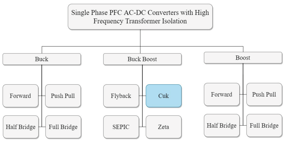
- Singh, B.; Singh, S.; Chandra, A.; Al-Haddad, K. Comprehensive study of single-phase ac-dc power factor corrected converters with high-frequency isolation. IEEE Trans. Ind. Inform. 2011, 7, 540–556. [Google Scholar] [CrossRef]
- Bist, V.; Singh, B. A brushless dc motor drive with power factor correction using isolated zeta converter. IEEE Trans. Ind. Inform. 2014, 10, 2064–2072. [Google Scholar] [CrossRef]
- Bist, V.; Singh, B. Pfc cuk converter-fed BLDC motor drive. IEEE Trans. Power Electron. 2014, 30, 871–887. [Google Scholar] [CrossRef]
- Bist, V.; Singh, B. A unity power factor bridgeless isolated cuk converter-fed brushless dc motor drive. IEEE Trans. Ind. Electron. 2014, 62, 4118–4129. [Google Scholar] [CrossRef]
- Singh, P.K.; Singh, B.; Bist, V. Brushless dc motor drive with power factor regulation using landsman converter. IET Power Electron. 2016, 9, 900–910. [Google Scholar] [CrossRef]
- Manglik, S.; Sundeep, S.; Singh, B. Brushless dc motor based ceiling fan using buck-boost converter. In Proceedings of the 2016 IEEE 7th Power India International Conference (PIICON), Bikaner, India, 25–27 November 2016; pp. 1–6. [Google Scholar]
- Kumar, A.; Sharma, U.; Singh, B. Pmbldc motor based ceiling fan using an isolated pfc zeta converter. In Proceedings of the 2020 IEEE International Conference on Power Electronics, Smart Grid and Renewable Energy (PESGRE2020), Cochin, India, 2–4 January 2020; pp. 1–6. [Google Scholar]
- Kumar, A.; Sharma, U.; Singh, B. Bldc motor ceiling fan using a bridgeless isolated pfc sepic converter. In Proceedings of the 2020 IEEE 9th Power India International Conference (PIICON), Sonepat, India, 28 February–1 March 2020; pp. 1–6. [Google Scholar]
- Amirkhanian, H.; Oknaian, S. Power loss breakdown in bldc drives applications using matlab. In Proceedings of the International Exhibition and Conference for Power Electronics, Intelligent Motion, Renewable Energy and Energy Management, Nuremberg, Germany, 5–7 June 2018; pp. 1–5. [Google Scholar]
- Infineon Technologies AG. Block Commutation vs. Foc in Power Tool Motor Control. Available online: https://www.infineon.com/dgdl/Infineon-Motor_power_tool_Block_Commutation_vs_FOC-ApplicationNotes-v01_00-EN.pdf?fileId=5546d4626eab8fbf016ed37fee474a65 (accessed on 4 January 2021).
- Sasaki, H.; Asai, K.; Gohara, Y.; Moroizumi, M. Motor Control Circuit and Fan Including the Same. U.S. Patent 10,003,288, 19 June 2018. [Google Scholar]
- Huang, L.-Q.; Chang, Y.-C.; Liu, Y.-G.; Liang, Z.-J. Ceiling Fan, Method for Controlling Ceiling Fan Motor and Control Device for Ceiling Fan Motor. U.S. Patent 10,374,536, 6 August 2019. [Google Scholar]
- Rissetto, R.; Schweiker, M.; Wagner, A. Personalized ceiling fans: Effects of air motion, air direction and personal control on thermal comfort. Energy Build. 2021, 235, 110721. [Google Scholar] [CrossRef]
- Williams, B.W. Transformer isolated buck-boost converters. Renew. Energy Sustain. Dev. 2016, 2, 112–125. [Google Scholar] [CrossRef]
- Ramanath, A.; Kshirsagar, A.; Thamballa, S.; Mohan, N. Equivalent Modeling, Design and Analysis of Integrated Magnetics Ćuk Converter. In Proceedings of the 2019 North American Power Symposium (NAPS), Wichita, KS, USA, 13–15 October 2019. [Google Scholar]
- Biswas, S.; Mohan, N.; Robbins, W. A systematic design method and verification for a zero-ripple interface for PV/Battery-to-grid applications. In Proceedings of the 2016 IEEE Applied Power Electronics Conference and Exposition (APEC), Long Beach, CA, USA, 20–24 March 2016. [Google Scholar]
- Singh, S.; Singh, B. A voltage-controlled pfc cuk converter-based pmbldcm drive for air-conditioners. IEEE Trans. Ind. Appl. 2012, 48, 832–838. [Google Scholar] [CrossRef]


| Motor Type | Advantages | Disadvantages |
|---|---|---|
| Induction Motor [4] | No drive circuit required | 2 windings required for starting |
| Simple speed control mechanism | Additional rotor current generates heat which is dissipated as loss | |
| Brushless DC Motor [7,8,9] | Has high efficiency due to permanent magnet on rotor | Needs a motor driver circuit |
| Since winding is for low voltage, system is easily integratable with low voltage sources like solar panel | Some stator current ripple is present due to commutation and ripples in DC power supply | |
| Mostly, the winding is for low voltage, and thus voltage conversion is required | ||
| Permanent Magnet Synchronous Motor [4,6,8,9] | More efficient than induction motor and BLDC motor | More expensive manufacturing process than BLDC motor. |
| Designs | Advantages | Disadvantages |
|---|---|---|
| Isolated Zeta converter-based design with block commutation [23] | Speed of motor varies by simply varying output voltage of the converter. | No short circuit protection due to DCM mode of operation with voltage follower method. |
| Non-isolated Cuk converter-based design [24] | Improved power quality in both CCM and DCM modes | Operation in CCM is expensive due to requirement of current sensor. Inappropriate for low output voltage drives because of non-isolated design |
| Bridgeless Isolated Cuk converter-based design [25] | Improves power quality by operating only in DCM mode | The cost is high due to requirement of multiple switches. Not suitable for low cost applications |
| Landsman converter-based design [26] | Improved power quality and efficiency | Inappropriate for low output voltage drives because of non-isolated design |
| Designs | Advantages | Disadvantages |
|---|---|---|
| Non-isolated buck–boost converter-based design [27] | Near-unity PF and low THD | Is based on non-isolated design and is thus only suitable for high voltage BLDC motors |
| Zeta-based design with DC link voltage-based speed control [28] | Low switching losses due to low frequency switching | Has high switch and body diode conduction losses in switches of the VSI |
| Near-unity power factor | Discontinuous input current | |
| Continuous output current | ||
| Isolated design | ||
| SEPIC-based design with DC link voltage-based speed control [29] | Low switching losses due to low frequency switching | Has high switch and body diode conduction losses in switches of the VSI |
| Near-unity power factor | Discontinuous output current | |
| Continuous input current | ||
| Isolated design |
| Parameter | Value |
|---|---|
| Input Voltage | 90 V–270 V AC |
| Output Voltage | 15 V DC |
| Maximum Output Power | 50 W |
| Maximum Total Harmonic Distortion | 15% |
| Minimum Power Factor | 0.90 |
| Notation | Parameter | Value |
|---|---|---|
| Switching frequency | 50 kHz | |
| D | Duty cycle | 0.3 to 0.75 |
| Maximum magnetic flux density | 0.47 T | |
| Fill factor of the transformer | 0.4 | |
| Current density in all the windings | 4 A/mm | |
| Relative permeability of ferrite core | 1790 | |
| Mean magnetic path length of core | 79 mm |
| Notation | Parameter | Value |
|---|---|---|
| Number of turns in transformer primary winding | 55 | |
| Number of turns in transformer secondary winding | 7 | |
| Number of turns in primary inductor winding | 55 | |
| Number of turns in secondary inductor winding | 7 | |
| g | Air gap in the transformer core | 1.1 mm |
| Component Type | Converter | Quantity/Type | Cost Description |
|---|---|---|---|
| MOSFET | Flyback, SEPIC, Zeta, Zuk | 1 | Switch cost is the same for all the converters due to identical voltage and current stress |
| Diodes | Flyback, SEPIC, Cuk | 1 | Diode cost is the same for these three converters due to identical voltage and current stress |
| Zeta | 1 | Diode cost is slightly higher in this converter due to slightly increased current stress | |
| High Frequency Transformer | Flyback | 1 | The flyback transformer is bigger, hence more costly. Essentially, this is not a transformer but an inductor that stores energy in the air gap of the cores |
| SEPIC, Zeta | 1 | These transformers require smaller core and overall volume for the same power rating since they behave as coupled inductors | |
| Cuk | 1 | These transformers require the smallest core and overall volume for the same power rating because of their behavior as coupled inductors | |
| Inductors | Flyback | 0 | No inductors required |
| SEPIC, Zeta | 1 | One inductor required in each | |
| Cuk | 2 | Two inductors are required that are coupled together by winding them within the high frequency transformer core | |
| Capacitors | Flyback | 1 | Low voltage output capacitor |
| SEPIC | 2 | In addition to the output capacitor, one intermediate capacitor is required at the high voltage side | |
| Zeta | 2 | In addition to the output capacitor, one intermediate capacitor is required at the low voltage side | |
| Cuk | 3 | In addition to the output capacitor, two intermediate capacitors are required at both the high and low voltage sides | |
| Drive Circuitry | Flyback, SEPIC, Cuk | Low side | Gate drive circuitry requirements are simple and cost effective |
| Zeta | High side | Conventionally, it uses a high side switch that has more complex and expensive gate drive circuitry |
Publisher’s Note: MDPI stays neutral with regard to jurisdictional claims in published maps and institutional affiliations. |
© 2021 by the authors. Licensee MDPI, Basel, Switzerland. This article is an open access article distributed under the terms and conditions of the Creative Commons Attribution (CC BY) license (https://creativecommons.org/licenses/by/4.0/).
Share and Cite
Khan, H.R.; Kazmi, M.; Ashraf, H.B.; Hashir Bin Khalid, M.; Hasan, A.; Qazi, S.A. An Isolated Power Factor Corrected Cuk Converter with Integrated Magnetics for Brushless DC Ceiling Fan Applications. Electronics 2021, 10, 1720. https://doi.org/10.3390/electronics10141720
Khan HR, Kazmi M, Ashraf HB, Hashir Bin Khalid M, Hasan A, Qazi SA. An Isolated Power Factor Corrected Cuk Converter with Integrated Magnetics for Brushless DC Ceiling Fan Applications. Electronics. 2021; 10(14):1720. https://doi.org/10.3390/electronics10141720
Chicago/Turabian StyleKhan, Hashim Raza, Majida Kazmi, Haris Bin Ashraf, Muhammad Hashir Bin Khalid, Abul Hasan, and Saad Ahmed Qazi. 2021. "An Isolated Power Factor Corrected Cuk Converter with Integrated Magnetics for Brushless DC Ceiling Fan Applications" Electronics 10, no. 14: 1720. https://doi.org/10.3390/electronics10141720
APA StyleKhan, H. R., Kazmi, M., Ashraf, H. B., Hashir Bin Khalid, M., Hasan, A., & Qazi, S. A. (2021). An Isolated Power Factor Corrected Cuk Converter with Integrated Magnetics for Brushless DC Ceiling Fan Applications. Electronics, 10(14), 1720. https://doi.org/10.3390/electronics10141720