1. Introduction
The interfaces currently in automotive vehicles mostly depend on mechanical buttons to act on the control of several functionalities inside the car cabin, which include opening and closing door windows, adjusting the position of rear-view mirrors, handling multimedia systems, air conditioning, navigation, etc. [
1].
Because they are composed of several moving parts, mechanical buttons support a limited number of uses—or cycles—due to the wear and tear that results from their continuous utilization [
2]. Other technological areas, such as multimedia, information technology, telecommunication systems, or even medical devices, have overcome this obstacle over the past two decades, changing the paradigm of the interfaces of their products by adopting technologies that are based on touch sensors [
3,
4].
A sensor is a device that reacts to stimulus [
5]. It is used to measure physical quantities, such as temperature, humidity, radiation, or light, among many other possibilities. In the context of this study, we will always be referring to electrical sensors, whcih is, devices that, in the face of a variation of a given physical quantity, manifest themselves in a variation of an electrical quantity (e.g., voltage, current, impedance). This variation is always the result of a stimulus.
However, a simple sensor is rarely able to effectively measure a quantity, due to limitations that typically show their influence in the form of non-linear behavior [
6], the presence of noise, or degradation of performance throughout use over the years. In order to overcome these limitations, it is common to use a complementary electronic signal conditioning system in association with the sensor, such as amplifiers, filters, or even microcontrollers. By using microcontrollers, we gain the ability to process, store, and communicate data between different devices. One particular disadvantage lies in the need to implement additional electronics and the corresponding increase in production costs.
There are several touch sensor technologies available today, which provide different properties and costs:
inductive sensors;
infrared sensors;
ultrasound sensors;
resistive sensors; and,
capacitive sensors.
Different sensors show distinct advantages and disadvantages. The analysis of each sensor technologies is performed in the context of this article. The tests and analysis conducted concluded on the appropriateness of coupling capacitive touch sensors [
7,
8] with a piece of injected plastic several millimeters thick, to serve as an interface [
9] for controlling the opening and closing of door windows, as well as for positioning rear-view mirrors from inside a vehicle’s cabin. We used a microcontroller-based system to acquire the touch signals and execute the control algorithm. We have found that this approach adds value to the product, as it is programmable and, thus, presents the necessary flexibility to adapt to different models of the same car range, as well as other vehicles in new contexts and applications. Because it is programmable, it can also be updated by reprogramming the car’s control software (without hardware intervention) in order to integrate new context-dependent interactions, such as controlling the multimedia system, the temperature of the car, air conditioning, navigation, the driving inherent functionalities of the car, or even to accommodate future requirements of the vehicle [
10] that are unforeseen at this stage of development. The integration of these systems with self-driving cars where disruptive technologies and functionalities may have to be integrated soon us ine aspect that deserves particular attention. Implementing these new functions as simply as possible can make more sense with touch-based sensors that are placed in unusual positions inside the cabin, e.g., on the steering wheel, roof, bank seat, etc. [
11]. A secondary aspect that assumes increasing importance and, thus, requires even more attention from the automotive manufacturers regards the continuous integration of the smartphone with the car cabin [
12]. Additionally, in this context, the integration of touch-based sensors can favor this approach.
Moreover, the association of this technology with injected plastic molding allows for rethinking the design of components for the car cabin control panels as both decorative and functional elements—now designed together and not as separate parts—that are geometrically aligned and combined to produce a more compact desired functionality and visual effect [
13].
This article presents the following contributions
the analysis and comparative study of touch sensors for the automotive industry;
study on the incorporation and functionality of capacitive sensors in injected plastic;
the incorporation of microelectronics to control capacitive sensors;
development and validation of an experimental case-study to control the opening and closing of car door windows, and the position of electric rear-view mirrors; and,
production, implementation, and testing of the prototype developed in an industrial context, on a real car manufactured by an international group.
This work is also part of the ’Collective Efficiency Strategies’, being totally aligned with the ’Mobinov—Automobile Cluster Association’, which identified “to contribute to making Portugal a reference in research, innovation, design, development, manufacture and testing of products and services of the automotive industry” and “strengthen the competitiveness of a fundamental sector of the economy, promoting an increase in exportation” as some of its main goals [
14].
This article is structured, as follows.
Section 2 describes the materials and methods used, analyzing, in depth, the available touch sensor technologies that are available and the criteria used to select, among these technologies, the most suitable for the current context in the automotive industry.
Section 3 analyzes the approaches and methods used to integrate injectable plastic with touch sensors and which polymers are the most suitable for this purpose. The experimental results are discussed in
Section 4 and
Section 5 closes the article.
2. Materials and Research Methods
A sensor device responds to a change in the surrounding physical environment, which translates to a variation of an electrical charge. The present work addresses a specific family of sensors in view of their use when integrated with injected plastic parts to control the functionalities in the car cabin—touch sensors.
2.1. Touch Sensors
Touch sensors allow the detection of human touch or the proximity of an object for human interaction. Its adoption is expanding in an increasing range of devices, products, and technologies, as it replaces buttons and mechanical switches, as well as potentiometers and encoders. Such levels of replacement imply several benefits, such as increased equipment durability and reliability when compared to devices made up of a set of mechanical parts. The appearance of touch-based devices can also be more appealing and attractive to the end user.
Its operation is based on the principle of a normal mechanical button. A flow of electrical current is generated in the sensor whenever it is touched (no pressure or movement of mechanical parts is required). The current flow is interrupted when the sensor is no longer touched. The automatic detection of this current variation allows the system to be controlled to act accordingly (e.g., opening or closing door windows).
There are several types of touch sensors, namely inductive, infrared, ultrasound, resistive, or capacitive ones. They all present advantages and disadvantages, which are analyzed below.
Inductive sensors need to be excited at both the sensor and touched object (for example, see the case of RFID cards [
15]). Ultrasonic sensors [
16] are large in size, and they require additional electronics and processing on the receiver end. In the same way, infrared sensors have limitations between the emitter and receiver that are essentially related to distance and the need for additional electronics. Resistive sensors are generally cheaper and allow activation with any object that precedes the sensor, however they are not very accurate. A capacitive sensor consists of only one conductive electrode [
17], which, in the presence of a contiguous object, alters its electrical characteristics, namely the capacitance. This change can be accurately measured. When considering that the touch is to be performed by a human finger, and while taking the analysis of important criteria imposed by industry, such as cost, precision, sensitivity, and dimension into account, the sensors that assume greater prominence and relevance in view of the intended use are of the resistive or capacitive type. The next subsections provide detailed analysis of each one of these sensors, with a view to the selection of the most appropriate device for the present automotive context.
2.1.1. Inductive Sensors
Inductive sensors are widely used to validate touch devices. Good examples include the metro ticket, house keys, car keys, and many other beacons that we use on a daily basis. These types of sensors are not ideal for applications that are activated by human touch, as their operating principle resides in the specific resonance frequency that is created through an electronic circuit by operating a coil with an oscillator. Faraday’s law explains the sensor’s working principle:
where
e represents the electromotive force,
N is the number of turns of wire,
is the magnetic flux, and
t is the time constant. A sensor is composed by several components:
By observing the diagram presented in
Figure 1, we conclude that the use of inductive sensors for the present application is not suitable for several reasons, namely: cost, need to incorporate additional electronics, complexity, and the presence of magnetic fields is not viable with the interaction of the human body.
2.1.2. Infrared Sensors
Infrared screens have light-emitting diodes, as well as receivers parallel to these diodes, along the frame of the entire panel. This way, the beams are interrupted whenever a human finger touches the screen (see
Figure 2). We can perceive the coordinates of the touch by knowing which specific beams are interrupted.
There are numerous advantages associated with this type of panel. The smooth recognition of touch and gestures, as well as short response times, are two crucial properties in this type of technology. It is usually applied in large screens, allowing, for example, outdoor usage. There are also disadvantages with the use of this technology, such as, for example, the greater probability of false activations. Whenever a foreign body comes into contact with the interface, the infrared beam is blocked and an activation occurs [
19]. Another disadvantage lies in cost, given that it is significantly more expensive than other devices offering a similar purpose.
2.1.3. Ultrasound Sensors
Ultrasound sensors detect objects by measuring the travel time of an acoustic signal that is emitted by it in order to discern whether there is an object in front of the sensor. The most well known application is the parking sensor array in the back of vehicles.
Ultrasound touch panels are currently under development, with the intention that it will be possible to accurately determine the touch as well as the magnitude of the touch. This technology can also be used to detect a fingerprint on a panel, as it allows for a scan of the object that performs the touch. This technology has already been applied to LCDs that analyze users’ fingerprints through the screen. It is often referred to as a technology that allows the 3D detection of a touch, because, in addition to the touch coordinate, it also allows obtaining depth information.
Through intense miniaturization, it is possible to embed an ultrasound transducer in a silicon chip, making it possible to produce sensors as small as 3 mm
2 [
20], which, if arranged in a grid pattern, become suitable for detecting touch and discern gestures. In the realm of innovation, this technology enables the use of uncommon materials for the touch interface, such as glass and metal. Because it remains a new technology, it is still expensive and inaccessible for experimentation.
2.1.4. Resistive Sensors
Resistive sensors detect the pressure on the surface and, thus, obtain better performance when it comes to the use of pens, gloves, or devices to perform the touch.
These sensors are made with two layers of a conductive material (or non-conductive, covered with a conductive film), which are separated by small spaces. The instant the body presses the surface of the sensor, the upper layer flexes and comes into electrical contact with the bottom layer, creating a potential difference. The contact point of the electrodes present in the layers is automatically obtained based on X-Y coordinates due to the particular voltage drop generated.
There are different types of resistive touch sensors:
4 wires;
5 wires; and,
8 wires.
The 4 and 5 wire resistive touch panels are similar, with the electrodes on the bottom layer, the former being less expensive, and the latter more resistant. It should be noted that the 4-wire panel also allows for measuring the pressure of the touch against its surface. The lower the resistance measured at the touch, the greater the pressure exerted [
21]. The 8-wire touch panels represent higher complexity, as they provide greater measurement meridians along the panel.
Figure 3 illustrates the functioning of a resistive panel:
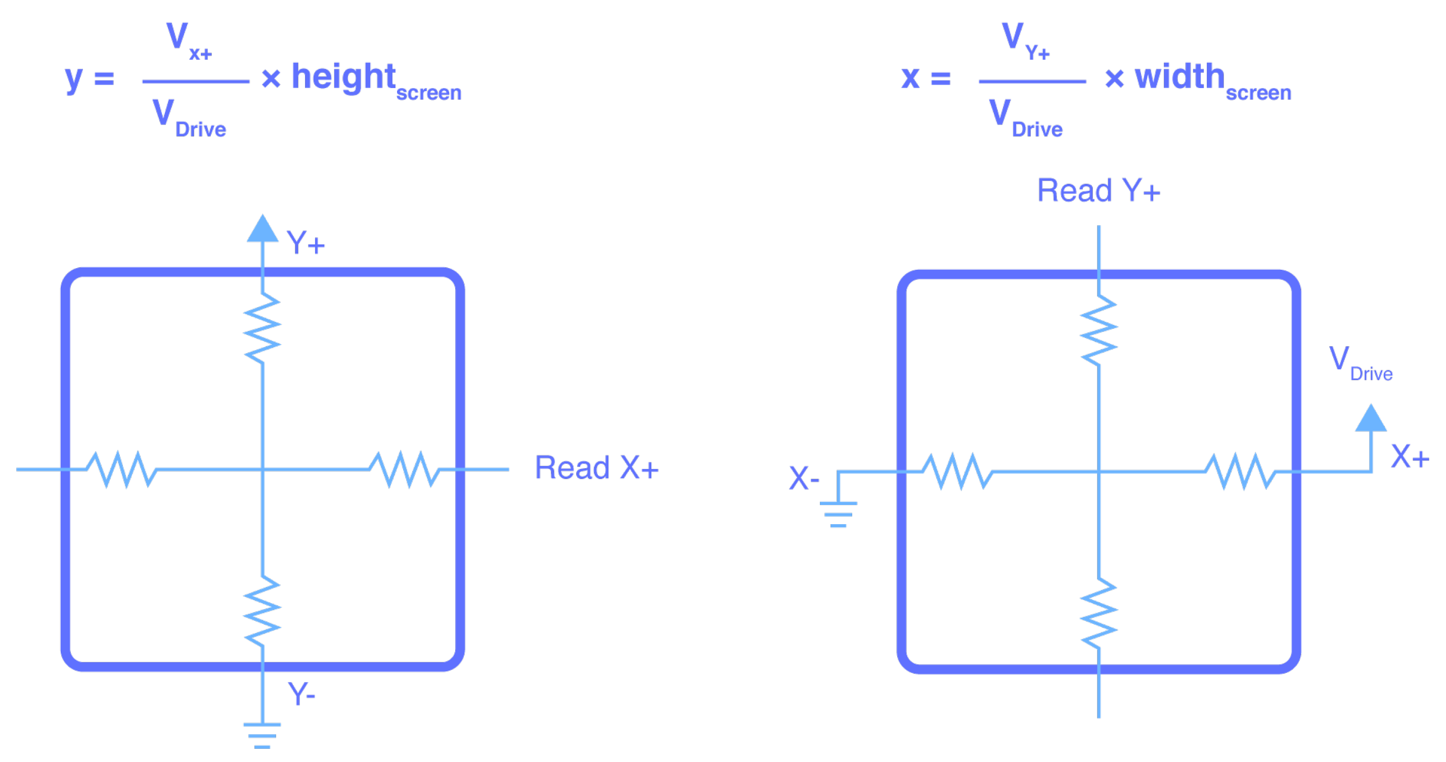
Figure 4 illustrates a resistive panel, where two electrodes are visible on each surface arranged perpendicularly, forming a matrix. The electrodes are connected by four wires to the display controller.
During standby position,
X+ is grounded, while
X+ and
Y+ are both at high impedance states, and
Y- is a pull up. The measurement of a 4-wire resistive panel is performed in two stages, the first for one coordinate, then the other. For measuring the
X coordinate,
X+ is connected to GND,
X- to VCC,
Y+ is high impedance and
Y- connected to the ADC. For measuring the
Y coordinate,
X+ is high impedance,
X- connected to the ADC,
Y+ to GND and
Y- to VCC. The (x, y) position is then given by the following equations:
The resistive type sensors are being progressively replaced by capacitive sensors, as it is necessary to exert a higher pressure to produce the expected feat, thus showing less sensitivity. However, they continue to be used in devices subject to harsh environments, as they are typically more resistant.
2.1.5. Capacitive Sensors
Capacitive sensors are currently widely used in portable devices, such as phones, tablets, and computers, as well as for a wide variety of home appliances and other electronic devices. There are many advantages, including: durability, robustness, and the possibility of building electronic devices with a more attractive design.
The operating principle is analogous to that of a simple capacitor. Two conductive plates are separated by an insulating material where the
C capacitance translates to:
where
represents free space permittivity,
is the relative permittivity or dielectric constant,
A the capacitive plate area, and
d the distance in between.
By analyzing Equation (
4), it can be seen that, in the installed system
,
and
A are constant. Thus, the capacitance changes are inversely proportional to the distance between the plates as depicted in
Figure 5.
In a capacitive sensor, the sensing electrode is one of the plates. The second electrode (second plate) consists of two factors: the first is
, referring to a parasitic capacitance of the surrounding environment and the other factor is the human finger, which, being conductive, creates a capacitance
(please see
Figure 6). This way,
and
form a parallel, increasing the total capacitance (capacitive devices in parallel, add up their effect). The inspection of the model in
Figure 6 shows that the capacitance is lower in the absence of a finger, and higher in the presence of the human part. Additionally, in the presence of the finger, the total capacitance is the sum of the capacitance
and
.
The
of plastic materials, which varies between 0.95 and 1.00, is an important aspect for further validation of the applicability of this technology [
25]. These parameters are important, as they affect the sensor calibration. Subsequently, the sensor electrode is connected to an electronic circuit that periodically reads its capacity.
There are several analog measurement methods for detecting the presence of an object/finger while using a capacitive sensor: resonance frequency change; frequency modulation; amplitude modulation; charge time measurement; and, duty cycle. Most of the methods require intensive analog circuits that inherit problems, like crosstalk, coupling, and noise sensitivity. However, a digital approach, with dedicated integrated circuits, consumes less area and energy when compared to analog solutions.
2.2. Evaluation of Processes and Materials
This section discusses the advantages and limitations of the distinct sensing technologies introduced above. In particular, it analyzes and evaluates their differentiating characteristics, allowing for conscious decision making, which is being supported in the best interest of the SmartPlastic project.
2.2.1. Inductive Sensors
Advantages: inductive touch sensors show strong advantages in the following areas:
Touch and validation: systems where wireless contact and data validation are required. This is one of the great advantages of inductive touch sensors and, thus, these technologies are typically used in ATM cards (i.e., contactless), in tickets and public transportation passes, or in car keys.
Metal detection: inductive sensors are also widely used in metal detection and their first use was precisely to replace mechanical limit switches in industry. This application is also used for traffic accounting. Often, on roads and car parks, there are inductive loops for automatic vehicle detection.
Nuclear applications: inductive sensors are also used in nuclear applications, detecting variations in the electromagnetic field of a system that would have previously been stable.
Disadvantages: they show the following negative aspects:
Additional electronics: they need an exciter or metallic circuit on one side of the system and a resonant circuit on the other.
Complexity: the implementation of an inductive sensor has several stages, which implies some additional electronics components and the need for proper signal processing conditioning.
2.2.2. Infrared Sensors
Advantages: these sensors are quite popular in a broad range of applications. The following aspects of this technology are highlighted:
Object detection: the use of infrared sensors is very common and it has been widespread in the area of object detection. The most common example of this application relates to garage gates.
Large touch screens: the principle used to detect a car at the garage door can be miniaturized to the point of achieving a high density of beams and, thus, can be applied to touch screens. They are primarily used in screens of enormous dimensions, which are generally located outdoors.
Counting systems: there are systems for counting people or vehicles that use infrared sensors.
Intrusion alarms: some of these systems also use infrared sensors to detect intruders.
Disadvantages: they present the following weaknesses:
Dimension: it is necessary that the sensors (as well as the application) occupy a considerable volume to work properly.
Limitation of the application on screens (I): it is only used in large screens. The incorporation of this technology is justified due to its reach (panels of several square meters).
Limitation of the application on screens (II): it can only be applied to flat screens.
Cost: the cost of an infrared sensor for a home gate is very low. However, the manufacture of a panel that uses this technology is much higher, because it uses an array of sensors of this type, thus increasing the number of devices and the construction complexity.
2.2.3. Ultrasound Sensors
Advantages: among the main advantages, we highlight:
Disadvantages: the main disadvantages are:
Cost: the cost per device is high and its application also entails high costs.
Applicability: for the intended purpose in the context of the current automotive application, the most interesting features that are associated with the use of this type of sensor are not observed.
2.2.4. Resistive Sensors
Advantages: The utilization of resistive sensors in touch panels shows several advantages.
Robustness: resistive panels are highly resistant and robust, which is why they are widely used in screen panels in the industry.
Use: they can be touched with objects, such as pens and gloves, which confers them an additional advantage in industrial use, namely regarding the use of personal protective equipment that is often used by operators.
Cost: they have a lower cost when compared to other technologies.
Disadvantages: however, they also show important disadvantages:
Sensitivity: touch sensitivity is reduced; therefore, it becomes necessary to exert some force to produce an effect on the screen, which makes the contact a little forced.
Manufacturing: the manufacture of this type of panels requires meticulous and high precision processes to produce the exact gap between the different layers of the sensor, which makes it difficult to carry out personalized experiments.
Cost: as mentioned in the previous section, resistive panels exist in different configurations. The most sensitive and accurate ones are in the form of 8 wire resistive panels, and this variant is expensive.
The cost of implementing ON/OFF buttons: The cost of implementing this technology to produce ON/OFF buttons is high. For the particular case of the present work, it would imply the use of a small panel/screen or a larger panel for controlling several ON/OFF buttons.
Applicability: bearing in mind that the present objective is to couple electronic sensor components near or inside the plastic after/during overmoulding, this solution would present reduced sensitivity, as it would take more force to execute a command. This issue also adds complexity to the mechanics of fixing the resistive panel.
2.2.5. Capacitive Sensors
Advantages: capacitive sensors have numerous advantages:
Ease of use and integration: the implementation of a capacitive sensor is relatively less difficult, as the utilization of a conductive material with an appropriate shape suffices. This way, there is a large number of possible shapes and implementations of a capacitive sensor, either through the use of stickers, the positioning of a conductor, or the utilization of a material with a proper shape that transmits mechanical properties, such as elasticity and resistance, which can change an electric field when activated.
Simple electronics: in view of the existing microchips for performing signal conditioning and capacitance measurement, the use of this technology and the consequent development of new components for human interaction are increasingly expanding.
Projected capacitance: it represents an evolution of capacitive screens that permit multi-touch and superior sensitivity. This technology consists of the manufacture of a panel in the middle, of which is a layer of any dielectric, and then on its two faces it has conductive surfaces with a matrix design (X, Y, or other personalized shape). These matrix conductors are constantly monitored by an electronic circuit that is sensitive to the change in the capacitance of a given coordinate (X, Y) on the panel.
Cost: this technology leads to the simplest and cheapest way of implementing ON/OFF buttons.
Disadvantages: the disadvantages of capacitive sensors are mainly related to the difficulty of detecting contact under certain circumstances:
Glove contacts: procedures of this type affect the capacitive panels/buttons, since gloves change sensitivity.
False triggers: the triggering of this type of sensors originated from external issues that do not represent a human finger (for example, a drop of water) is undesirable, but possible to mitigate. To minimize this problem, filters and the processing of dedicated algorithms are typically used, producing good results.
2.2.6. Comparison of Touch Sensor Technologies
The following table indicates the main characteristics that are listed by different technologies. All of the evaluations were conducted in relation to the objectives of the SmartPlastic project.
The distinction between the “On/Off Button” and “Panel” columns in the table refers to a simple two-state button and a flat 2D panel with X/Y dimensions. It allows a set of functionalities that vary with the precision of the panel.
Project applicability assesses the suitability of this sensor for the project’s objectives. Cost represents the general assessment of the cost of technology, including all of the electronics attached. Robustness evaluates the robustness of a sensor that was developed using these technologies. Integration evaluates the ease with which this technology can be integrated in different media/materials. The requirements to be met must meet dimension, additional electronics, the need for microcontrollers and programming, among others. The inspection of
Table 1 seems to indicate that a large set of properties can be more easily found in sensors of capacitive type.
2.3. Integration of Sensors with Microcontrollers
For the sake of flexibility and scalability in future production, in the development of the prototype we opted for using a microcontroller to perform the reading and aggregation of the signals coming from various touch sensors. There are several methods for connecting switches to a microcontroller and achieving the desired functionality.
2.3.1. Button Directly Connected to the Microcontroller
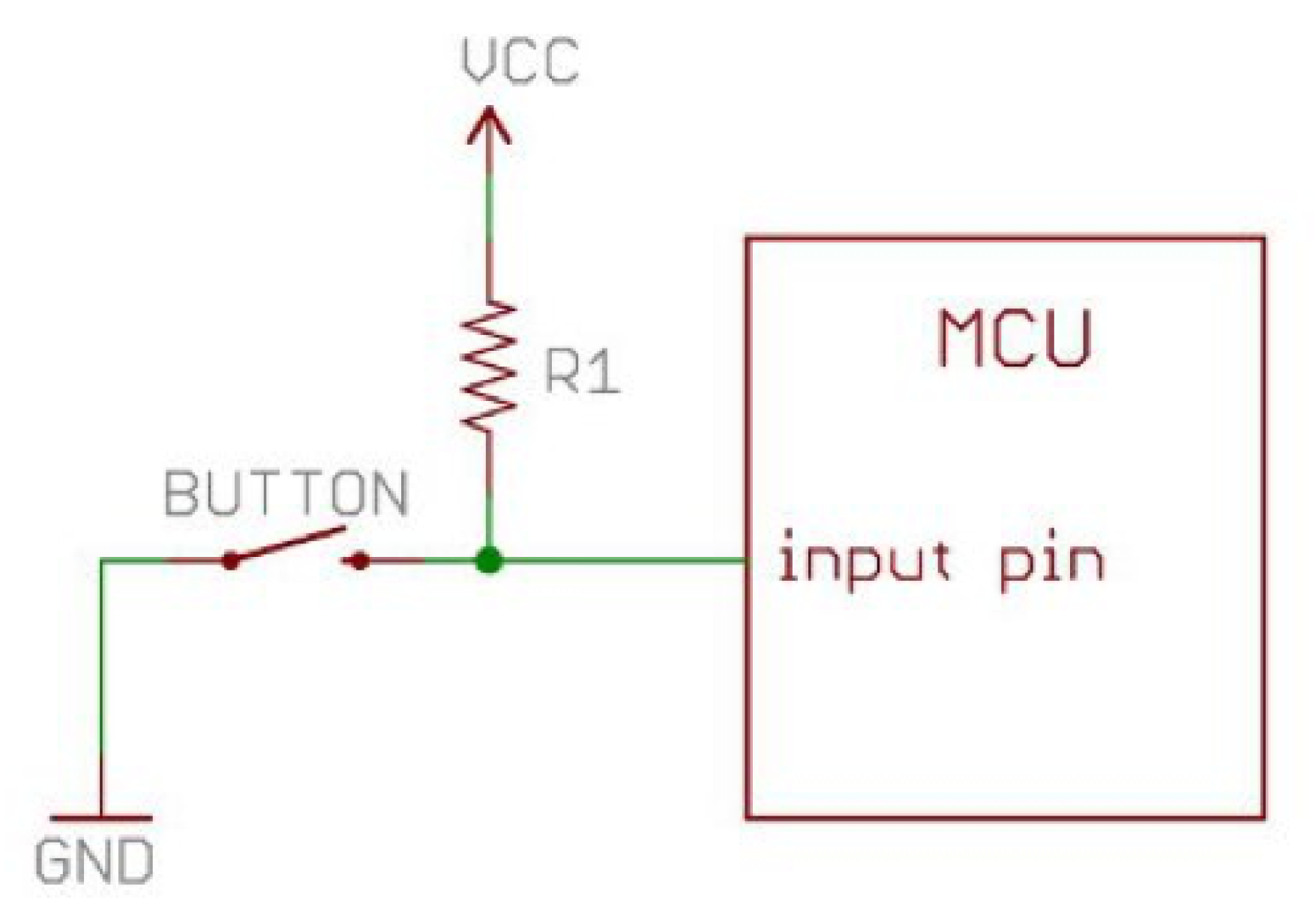
This is the most direct method, but it is rarely used, since each button uses a digital microcontroller pin, which are limited in number. The signal that is used in this type of assembly is usually digital, and the control can be made through a downward or upward slope (denied). For this, the characteristics of the microcontroller pins must be considered, and the type of “pull” to be inserted in the assembly—pull-up or pull-down, i.e., the device pulls current or supplies current—should match accordingly (see
Figure 7). It should be noted that, for the user, there is no difference between the two approaches. They both cause current to flow whenever an event occurs and the process is triggered from there.
2.3.2. Variable Voltage Drop
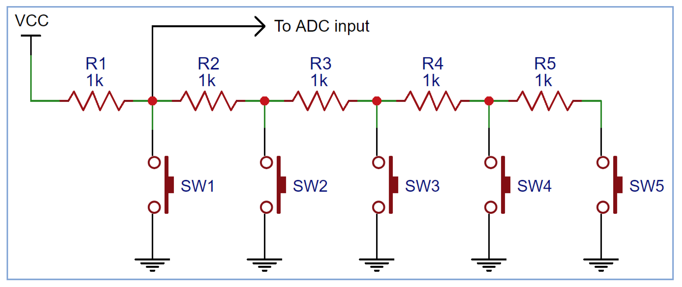
This method allows several buttons to be connected to a single pin of the microcontroller, which specifically has to be an analog-digital peripheral (ADC) that converts analog voltage levels into sequences of digital symbols (i.e., sequences of ’1’s and ’0’s).
The inspection of
Figure 8 shows that, without any button pressed, the voltage that is read by the ADC is equivalent to VCC. However, by pressing a button, the value read is different. For example, for VCC = 5 V:
pressing SW1 reads 0 V;
pressing SW2 reads VCC − (VCC/2) = 2.5 V;
pressing SW3 reads VCC − (VCC/3) = 3.33 V;
pressing SW4 reads VCC − (VCC/4) = 3.75 V; and,
pressing SW5 reads VCC − (VCC/5) = 4 V.
The analysis performed to the example circuit shown in
Figure 8 can be used a different number of buttons and other specific resistances. This is the approach employed in the car window lift control buttons provided for analysis and described later in the text.
2.3.3. Matrix with Row and Column Control
This approach is quite common in keyboards and, usually, in panels with many buttons. This technique more efficiently uses the available pins on the microcontroller chip. It allows for a greater number of buttons in relation to the number of occupied pins.
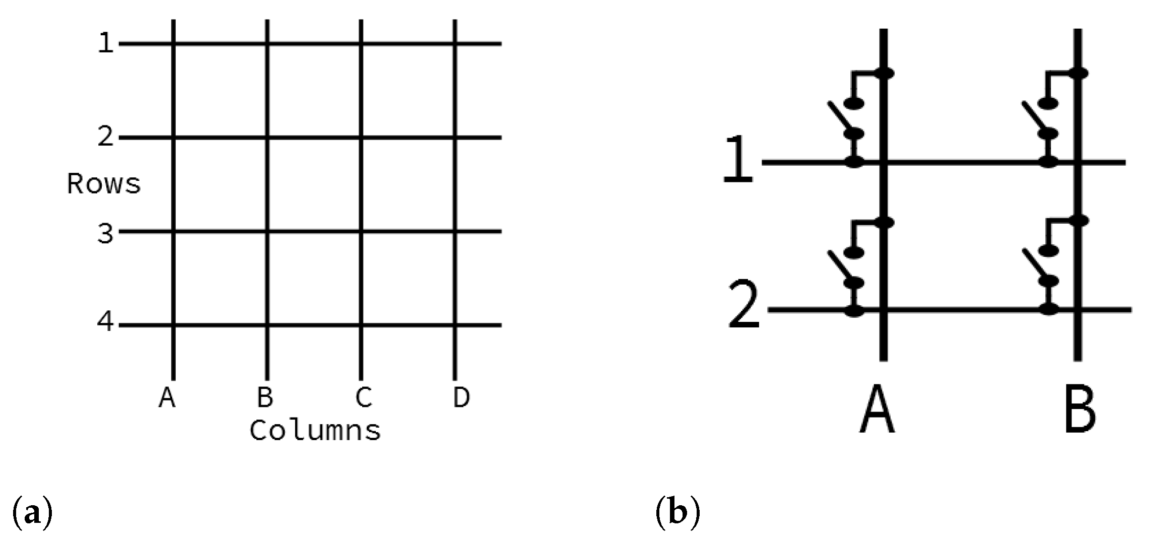
For the matrix topology, the number of buttons relates with the number of available pins on the following way:
4 buttons 2 rows & 2 columns = 4 pins
8 buttons 3 rows & 3 columns = 6 pins
16 buttons 4 rows & 4 columns = 8 pins
32 buttons 8 rows & 8 columns = 16 pins
This implementation requires some automation at the software level and some details at the hardware level. The use of this technique requires scanning rows and columns. In other words, the methodology requires that the columns (in
Figure 9 designated by letters) are configured as outputs and the rows (in the figure designated by numbers) configured as inputs. The columns are all set to HIGH (’1’), which is, all of the columns are connected to pins that are at a higher voltage and, one-by-one, scanned at LOW. At the same time, the scan of the rows takes place, and each pin (of the columns) is checked, in order to verify whether any column has the associated LOW value. This way, the pressed column at LOW state is known, together with the corresponding Y row, thus allowing to infer the coordinate of the button being pressed as illustrated in
Figure 10.
2.4. Communication Protocol with the Engine Control Unit (ECU)
In this study, a real automobile that was manufactured in 2018 is addressed. The operating mode and electrical functionality of door windows and rear-view mirrors are equally referenced under the context of this work.
2.4.1. Multiplex Door Panels Control System
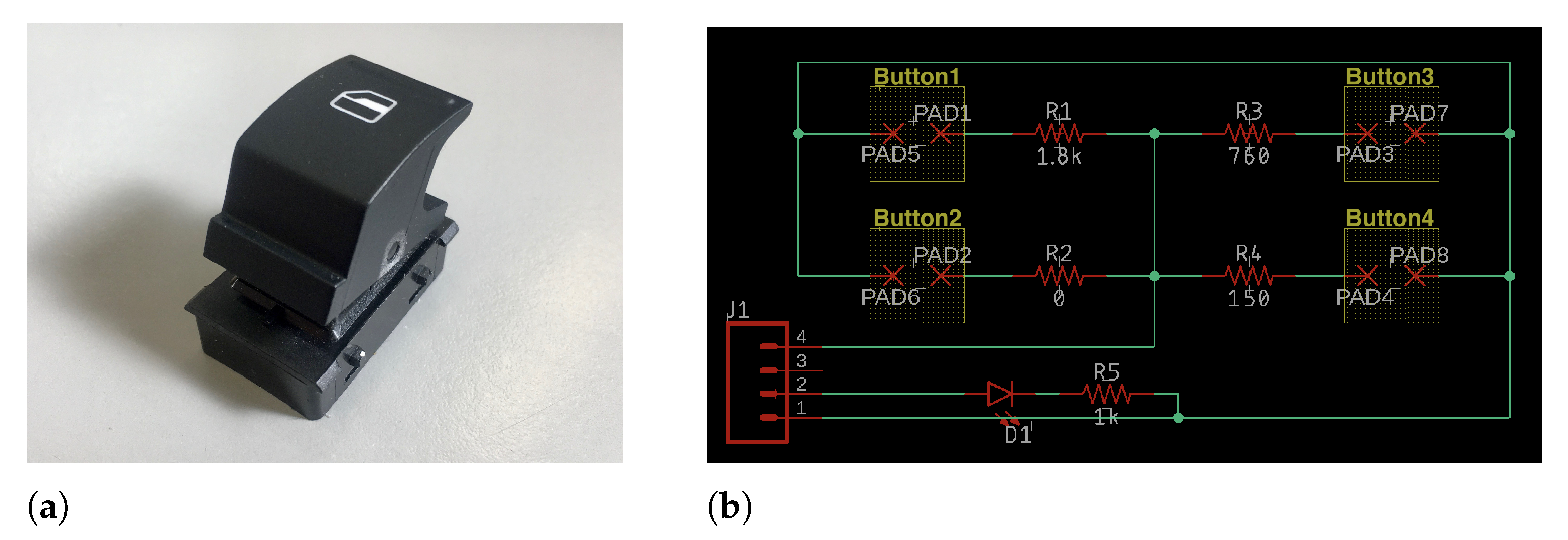
The functionality of this system consists of the actuation of four window panes with associated functions (descend, ascend, full descend, and full ascend), as well as a button to lock their actuation. There is no substantial amount of technical information available regarding the electrical properties of the system. These are regular buttons developed with polymers, electronic components, and metallic contacts. Nevertheless, there is a wide range of options for this functionality of a car door when looking at other similar products from the same manufacturer. Regarding communications, there are models with CAN, LIN, and “K interface” communication capabilities [
27,
28]. In terms of electrical characteristics, the supply voltages vary between 5 and 12 V, depending on the model. In the specific case of the vehicle that is used for investigation and development, the analysis of all components to be reproduced observes that the parts have more than one button. The simple command for a window pane is formed by four buttons: one button to raise the window, another to lower it, or to fully raise and fully lower it.
Figure 11 depicts such a command obtained from the tested vehicle and the corresponding electrical circuit.
2.4.2. Disassembling the Communication Protocol between Touch Sensor and ECU
In
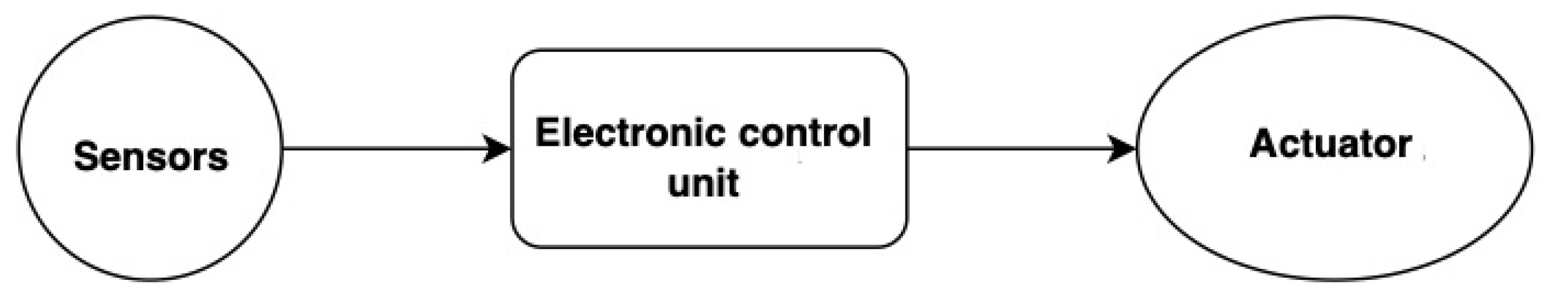
Figure 12, we can observe the operation of a car’s electronic system.
The ECU is the device that controls all of the electronic components and many mechanical components of an automobile [
29].
For the sensors to be read, the control unit has its own communication and protocol capabilities, as well as ADC and DAC ports. The system receives information from different points of the car through the respective sensors and it performs the necessary actions after processing that information. The operations range from raising or lowering the car door window, to injecting more or less fuel into the engine. For this purpose, the control unit also has a processing unit, memory, and internal communication ports. By observing this system, it is thus possible to perceive and extrapolate to the real case, when considering that a car today has several control units, each one performing specific tasks.
In the specific case under investigation, an experimental analysis was carried out by measuring the electrical signals between the door and the control unit under test [
30], thus obtaining a detailed pattern of behavior in relation to the observed signals (see
Figure 13). The signals do not vary only when the user performs a certain action. It was found that there is always a periodic signal that maintains its shape and frequency over time. Through further analysis, the perception is acquired that this signal is used in the automotive industry to perform diagnoses of the condition of the vehicle and its different parts [
31]. The analysis of this paper focuses on the signals measured during the actions of “going up”, “going up completely”, “going down”, and “going down completely”, for the left front window, since the method of operation of the remaining windows and other functions is similar.
In
Figure 14, we can observe the signals that were measured by probing the electrical circuits in the door panel.
The electrical values change according to the functionality requested, and they are:
Minimum: −48 mV;
Maximum: +368 mV;
Amplitude: 416 mV; and,
Frequency: 83 Hz.
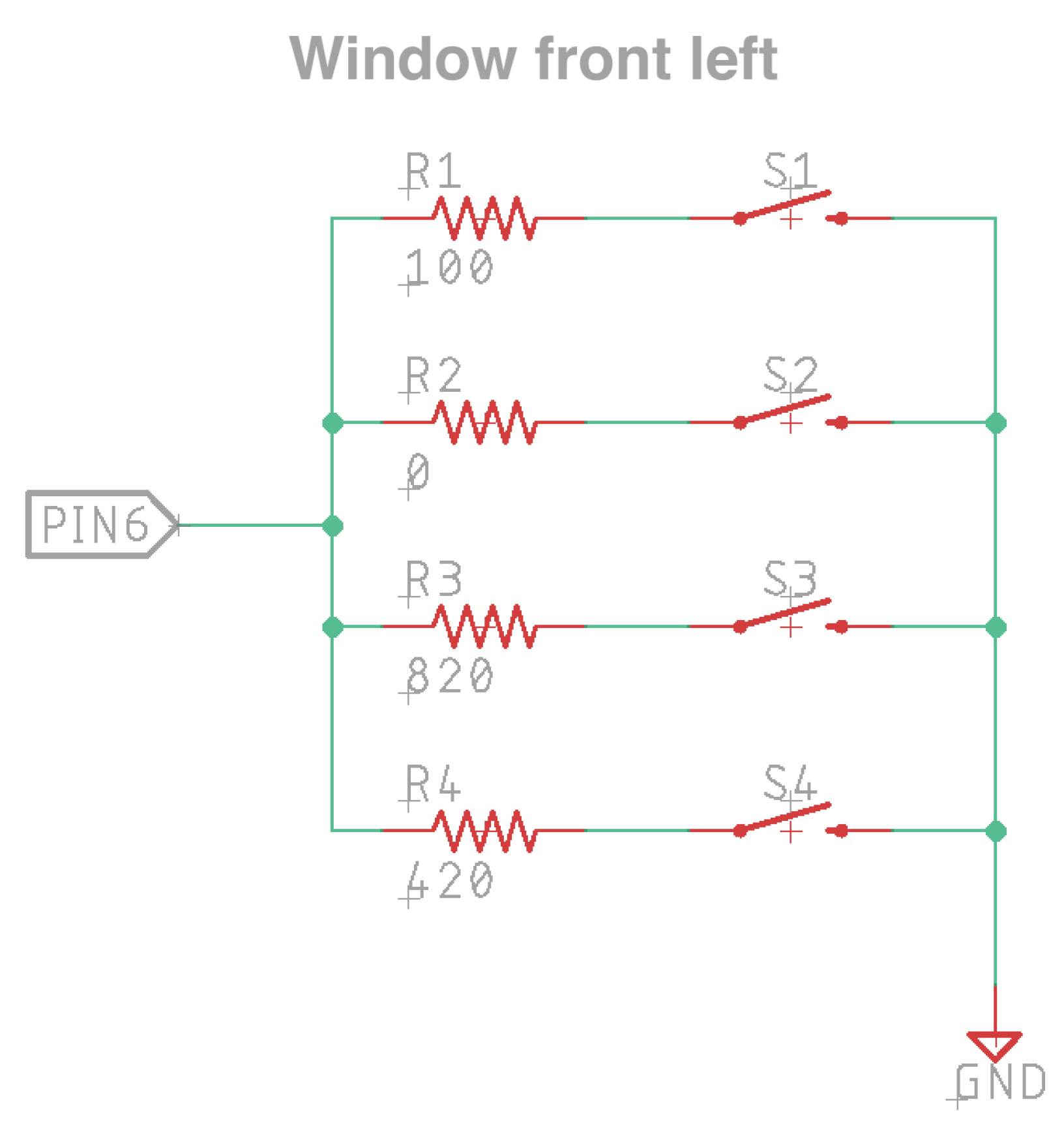
When analyzing the board referring to the button on the left front window pane, the electrical diagram shown in
Figure 15 is obtained.
A mechanical analysis of the button operation was also performed after analyzing the board of the tested button accessory and its circuitry. Thus, it was found that the first “click”, be it descending or ascending, is a simple contact button. However, the second “click” forms a parallel between the resistance of the first “click” and the second. Subsequently, we have the following definition for the four possible actions:
When comparing the circuit with the measured signals, there is a relationship and mechanism for actuation by voltage drop where a voltage divider is applied. In this way, it is concluded that, at this moment, the door does not have a communications protocol, but rather a purely analog interaction with the amplitude manipulation of a signal sent by the ECU.
3. Results
By analyzing the characteristics of the sensor technologies that were previously described in
Table 1, and when considering the desired use in the context of this project, in particular the criteria of robustness, ease of integration, and cost, the most adequate decision implies adopting sensors of capacitive type.
Capacitive sensors in a system can be used in several fields of application, such as replacing simple buttons, or using touch panels, sliders. Because they present a set of favorable characteristics, whereby their adequate sensitivity to touch and the reduced need to connect electronics that are dedicated to their operation stand out, capacitive type sensors are gaining popularity in several application areas. Cost also represents a very appealing factor, especially if purchased in large quantities. The advantages are numerous and they facilitate the specific implementation of the desired functionalities in the context of the SmartPlastic project.
Regarding the verification of whether some of the indicated disadvantages constitute an impediment to implementation, it appears that the operating environment (e.g., the car’s cabin) is sufficiently stable to the point that the normal operation of the device is not affected. In the event of unforeseen scenarios (e.g., an arm inadvertently placed over the sensor), it is always possible to correct this behavior by implementing filters and control algorithms using firmware.
3.1. Testing Capacitive Sensors with Different Polymers and Thickness Specifications
By testing several types of capacitive sensors composed of a simple copper pad on a PCB, and the TTP223B packaging integrated circuit, the experimental results were successful, even for plastic samples (placed near the sensor) that present greater thickness. The sensor proved to be sensitive to touch with a high success rate. The first tests were conducted on hundreds of samples and achieved an approximately 100% success rate in sensing human touch. It should be noted that the hand and touch-based sensor are on opposite sides of the plastic part. For the worst case scenario, plastic pieces as thick as 2.5 mm were perfectly able to detect the hand touch on the other side of the piece, obtaining sensitivity rates above 96.67% and 100% for most cases. These results can be observed from
Table 2,
Table 3,
Table 4,
Table 5 and
Table 6, where the type and thickness of the polymer tested are depicted for each of the sensors presented in
Figure 16 and
Table 7.
All of the pieces injected in relation to the present context of producing polymer components for controlling the opening of door windows and rear-view mirrors are less thick than the values that are indicated in
Table 2,
Table 3,
Table 4,
Table 5 and
Table 6. Therefore, it is possible to conclude that the objective of the project can be achieved without the need to resort to a necessarily more complex process that involves over-molding the sensors, as tested and illustrated in
Figure 17.
3.2. Integration of Capacitive Sensors with Microcontrollers on the PCB
Having validated the touch sensor technology, it was decided to design the sensors themselves on the PCB in order to reduce the costs and area of the circuit. We chose to integrate these sensors that were designed directly on the PCB with a microcontroller that had its own peripheral for conditioning and interpreting the signals emitted from these sensors. The microcontroller chosen was the ATtiny3217 from Microchip, which incorporates a Peripheral Touch Controller that abstracts the functions necessary to deal with capacitive sensors. By using this peripheral, it is advantageous to explore a method for connecting capacitive sensors, which is analogous to the “Matrix with row and column control” method described in
Section 2.3.3. This method of measuring the change in capacitance using a matrix electrode configuration is called Mutual Capacitance. This way, where only 10 sensors could be integrated using the “one sensor per pin” or Self Capacitance method, it now becomes possible to support up to 21 sensors using a matrix configuration with 3 rows and 7 columns.
Figure 18 illustrates the prototype developed that supports 19 capacitive sensors.
4. Analysis and Discussion
The purpose of SmartPlastic was to develop a technological alternative to an automobile part, which is the result of a complex fabrication process that employs several miniature components based on injected plastic, for controlling functionalities inside the car cabin. This part has a limited life-cycle as a result of this process and of the mechanical wear of the components.
The original automobile part that is responsible for the control of the door windows and rear-mirror’s movement used in tests is composed of 26 discreet components. Amongst them, there are several pieces made of plastic, rubber, metal, and PCBs with their respective electronic components and connectors as depicted in
Figure 19. The intricate design of the side mirror joystick is of particular interest (please see
Figure 19 c): this component employs a complex electromechanical system that is comprised of metal beads rolling along plastic grooves, closing electrical circuits to move the mirrors. This joystick component is made up of 12 components alone.
Each one of these components has its own production line and they all converge into an assembly line to complete the part mounting. These production lines need to obey specific tolerance limits, defined as an allowance for a specific variation in the size and geometry of a part [
32]. These variations in size and geometry add up along the production and assembly, which can result in a shortened life-cycle for the component. Assembly is of particular importance, because it usually is made by hand, which is never error free, takes more time than automation, and can lead to waste if a mistake occurs. There is an inherent cost to the OEM in all of these fault prone processes: the product quality. The shorter the product quality, the shorter its mean time between failures (MTBF) and, thus, the higher the maintenance and replacement costs.
After considering all of the above, the original part mechanism was analyzed to determine which functionality should be incorporated and emulated in the new part. Once those requirements were defined, the development of the new part was made using the least mechanical complexity possible.
The newly developed part is composed of two components: a PCB with its electronic devices and the molded polymer plastic surface. The polymer plastic component is the result of a proven automated process that requires no human intervention during fabrication. The PCB production and its electronic component’s assembly are both also automated and, thus, do not require human intervention during the entire process. The only intervention required was to join the PCB and surface components. Such a reduced level of complexity allows for smaller margins of error and faster production times, which results in higher productivity and better quality standards being met.
The plastic polymer surface was designed to allow the user to accurately feel where the hand should be placed in order to activate the controls (see
Figure 20a), without the need of looking at the polymer touch surface. This was accomplished by employing grooves along the touch controls and ridges between them during the design process. This requirement was of the utmost importance, as the driver needs to focus on the road while driving, and should avoid looking where the controls are. Therefore, the surface design is important enough to make every other development task, such as the PCBs, gravitate around it. The PCB was designed as a function of the surface limitations and functional requirements, as depicted in
Figure 20b.
As already noted, all of the development results in a substantial reduction of components production and assembly processes. The lesser amount of human intervention and, thus, probability of error, also contributes to a reduction in the production costs along the road. These factors are of extreme importance to the operator that is responsible for selling the vehicle to the end consumer, because the maintenance costs are a critical factor to be taken into consideration when deciding to buy a new vehicle. There is also a non-monetary cost involved, which is the improvement in the ecological footprint when comparing this newly developed part to the original mechanical part. This new part uses less plastic and it has a longer life-cycle—as a result of less production and assembly faults—which will invariably lead to less waste, even if the OEM decides to replace the part in the event of an operational failure to the detriment of repairing the faulty part. This improvement in reliability is the result of omitting moving mechanical components in the development of this new part. Those moving components are the main contributors to the wear of a part or product. Therefore, by employing no moving components and reducing the assembly complexity, there would be less potential points of failure, which can be measured in a longer MTBF.
There was some level of skepticism in the beginning of the investigation regarding this technology’s flexibility when paired to the types of polymers and associated thickness, which some manufacturers use, as well as in regards to the use of painting and surface finishing. This solution can be implemented using different polymers and thickness, which makes it a versatile option for different environments and contexts that require unusual designs and even extreme operating conditions, such as greater thermal resistance or greater resistance to mechanical stress, as shown in
Section 3.1. This way, this novel technology meets the requirements of different car manufacturers without the need of any type of physical adaptation.
The next step consists of the endurance validation for the developed part. The first tests allow for concluding that the number of failures is indeed small, being below 0.05%. This process will be mechanized and it is expected to allow the solution to be automatically validated running thousands of operating cycles. With this, the intention is to improve reliability and be able to decide which gestures and interactions are the most appropriate for using this solution in the originally proposed context, which is the control of windows and rear-mirrors on the driver’s side in the interior of a car cabin.
Considerations about Incorporation of Touch-Based Technology
There is some debate going on regarding the visual attention that the driver must pay to use touch-based screens and their maintenance as primary control interfaces, being supplemented by secondary devices that are only enabled for certain features [
33]. Independently of the chosen path, at later stages of evolution of the car cabin interfaces, the touch-based technology that is proposed in this work can be adopted with high gains in terms of development complexity, integration in the vehicle, ease-of-use, and cost.
5. Conclusions
The paradigm of carbon emissions reduction represents an important goal in the industrial context. In this work, we developed a new technology, which was supported by a case-study for opening/closing electric windows and controlling the rear-view system, which allows the plastic part’s number reduction in the manufacturing process through the replacement of a mechanical panel with touch sensors incorporated using low-cost electronics that were attached to a single injected plastic part. The production processes are further reduced, leading to reduced waste of the material, smaller environmental impact at the end of life, and less energy being spent on design.
By eliminating several parts from the current system, we obtain a cheaper component whose functionality is also easier to build and less prone to errors. This conclusion requires quantitative validation. However, the decrease in the number of hours of a human operator largely justifies the reduced cost of the part, rendering the economic study to an economy of scale less relevant.
Regarding the technological purpose of this work, at this stage of development there is a new technology that covers all of the features of its predecessor. However, it shows to be more versatile and able to be reprogrammed to integrate new features in the future, both from the manufacturer and the user, including presets for different vehicle users. This type of personalization, according to the driver, is an add-on that car manufacturers currently pursue with great interest.
What the Future Will Bring
Autonomous self-driving cars will become a reality soon and, supported by new artificial intelligence technology [
34], they will provide more functionalities to the passengers. It may be expected that the new concept of a car cabin changes accordingly, namely for the driver who is now going to be able to interact more with other passengers and eventually use the car seat in positions where he/she can face other passengers, thus not necessarily being aligned with the front direction of the vehicle. This may imply that control buttons will have to be integrated into the passenger’s seat, roof, or arm rest, and, in that case, buttons will have to become simpler and probably not formed by dozens of plastic parts each. Multi-function, re-programmable, and touch-based sensors, such as the solution proposed in this article, are excellent candidates that are ready to be adopted by these new cars and systems [
35].
Author Contributions
Conceptualization, C.A., T.C., P.S., J.S., C.R., R.L., R.P., F.M., R.M., G.T. and G.F.; methodology, C.A., T.C., P.S., J.S., G.T. and G.F.; software, C.A. and T.C.; validation, C.A., T.C. and G.F.; formal analysis, P.S. and G.F.; investigation, C.A., T.C., P.S., J.S. and G.F.; resources, P.S., G.T. and G.F.; data curation, P.S. and J.S.; writing—original draft preparation, C.A., T.C. and G.F.; writing—review and editing, P.S., C.R., R.L., F.M., G.T. and G.F.; visualization, J.S., R.P., R.M.; supervision, P.S. and G.F.; project administration, P.S.; funding acquisition, P.S. and G.T. All authors have read and agreed to the published version of the manuscript.
Funding
This work has been financially supported by project SPaC (POCI-01-0247-FEDER-038379), co-financed by the European Community Fund FEDER through POCI—Programa Operacional Competitividade e Internacionalização. It has also been financially supported by Instituto de Telecomunicações and Fundação para a Ciência e a Tecnologia under grants UIDB/50008/2020 and UIDP/50008/2020.
Acknowledgments
The authors would like to acknowledge the support provided by CJR Motors and Leiribéria.
Conflicts of Interest
The authors declare no conflict of interest.
Abbreviations
The following abbreviations are used in this manuscript:
| SPaC | Smart Plastic Cover |
| LCD | Liquid-Crystal Display |
| ADC | Analog-to-Digital Converter |
| DAC | Digital-to-Analog Converter |
| CAN | Controller Area Network |
| LIN | Local Interconnect Network |
| PCB | Printed Circuit Board |
| ECU | Engine Control Unit |
| MTBF | Mean Time Between Failures |
| OEM | Original Equipment Manufacturer |
| MDPI | Multidisciplinary Digital Publishing Institute |
| FEDER | Fundo Europeu de Desenvolvimento Regional (Portugal) |
References
- Krenicky, T.; Ruzbarsky, J. Alternative Concept of the Virtual Car Display Design Reflecting Onset of the Industry 4.0 into Automotive. In Proceedings of the IEEE 22nd International Conference on Intelligent Engineering Systems (INES), Las Palmas de Gran Canaria, Spain, 21–23 June 2018; pp. 407–412. [Google Scholar]
- Shaygi, M.; Wunderle, B.; Arnold, J.; Pflügler, N.; Pufall, R. Button Shear Fatigue Test: Fracture-Mechanical Interface Characterisation under Periodic Subcritical Mechanical Loading. In Proceedings of the 25th International Workshop on Thermal Investigations of ICs and Systems (THERMINIC), Lecce, Italy, 25–27 September 2019; pp. 1–12. [Google Scholar]
- Nunes, J.S.; Castro, N.; Gonçalves, S.; Pereira, N.; Correia, V.; Lanceros-Mendez, S. Marked object recognition multitouch screen printed touchpad for interactive applications. Sensors 2017, 12, 2786. [Google Scholar] [CrossRef] [PubMed]
- Kim, J.; Song, W.; Jung, S.; Kim, Y.; Park, W.; You, B.; Park, K. Capacitive Heart-Rate Sensing on Touch Screen Panel with Laterally Interspaced Electrodes. Sensors 2020, 14, 3986. [Google Scholar] [CrossRef] [PubMed]
- Yeh, S.-K.; Hsieh, M.-L.; Fang, W. CMOS-based tactile force sensor: A review. IEEE Sens. J. 2021. [Google Scholar] [CrossRef]
- Bae, J.; Hwang, Y.; Park, S.J.; Ha, J.-H.; Kim, H.J.; Jang, A.; An, J.; Lee, C.-S.; Park, S.-H. Study on the Sensing Signal Profiles for Determination of Process Window of Flexible Sensors Based on Surface Treated PDMS/CNT Composite Patches. Polymers 2018, 10, 951. [Google Scholar] [CrossRef] [PubMed]
- Park, J.K.; Lee, C.J.; Kim, J.T. Analysis of multi-level simultaneous driving technique for capacitive touch sensors. Sensors 2017, 9, 2016. [Google Scholar] [CrossRef] [PubMed]
- Brasseur, G. Design rules for robust capacitive sensors. IEEE Trans. Instrum. Meas. 2003, 52, 1261–1265. [Google Scholar] [CrossRef]
- Seo, S.-H.; Park, J.-H.; Hwang, S.-H.; Jeon, J.W. 3-D Car Simulator for Testing ECU Embedded Systems. In Proceedings of the SICE-ICASE International Joint Conference, Busan, Korea, 18–21 October 2006; pp. 550–554. [Google Scholar]
- Morales-Alvarez, W.; Sipele, O.; Léberon, R.; Tadjine, H.H.; Olaverri-Monreal, C. Automated Driving: A Literature Review of the Take over Request in Conditional Automation. Electronics 2020, 9, 2087. [Google Scholar] [CrossRef]
- Kouba, S.; Dickson, N. Intuitive Touch Technologies—Semiconductor-Based Electronic Components and their Integration. Auto Tech Rev. 2016, 5, 38–43. [Google Scholar] [CrossRef]
- Fleming, B. Advances in Automotive Electronics [Automotive Electronics]. IEEE Veh. Technol. Mag. 2015, 10, 4–96. [Google Scholar] [CrossRef]
- Miedl, F.; Tille, T. 3-D surface-integrated touch-sensor system for automotive HMI applications. IEEE/ASME Trans. Mechatron. 2015, 21, 787–794. [Google Scholar] [CrossRef]
- MOBINOV, An Aggregating Platform of Knowledge and Skills. Available online: https://mobinov.pt/index.php/en/ (accessed on 12 January 2021).
- Vojtech, L.; Lopez, A.M.F.; Neruda, M.; Lokaj, Z. Embedded system with RFID technology and inductive proximity sensor. In Proceedings of the 36th International Conference on Telecommunications and Signal Processing (TSP), Rome, Italy, 2–4 July 2013; pp. 213–217. [Google Scholar]
- Han, D.; Choi, H.B.; Kim, Y. Design of Road Surface Lighting System for Rear Lamp using Automotive Ultrasonic Sensor. In Proceedings of the International SoC Design Conference (ISOCC), Daegu, Korea, 12–15 November 2018; pp. 249–250. [Google Scholar]
- Rodríguez-Machorro, J.C.; Ríos-Osorio, H.; Águila-Rodríguez, G.; Herrera-Aguilar, I.; González-Sánchez, B.E. Development of capacitive touch interfaces. In Proceedings of the International Conference on Electronics, Communications and Computers (CONIELECOMP), Cholula, Mexico, 22–24 February 2017; pp. 1–8. [Google Scholar]
- Wang, H.; Jones, D.; de Boer, G.; Kow, J.; Beccai, L.; Alazmani, A.; Culmer, P. Design and Characterization of Tri-Axis Soft Inductive Tactile Sensors. IEEE Sens. J. 2018, 18, 7793–7801. [Google Scholar] [CrossRef]
- Liu, Y.; Liu, J.; Lin, H.; Zeng, L. Research on infrared signal processing circuit of large size infrared touch screen with interference rejection. In Proceedings of the IEEE International Conference on Signal Processing, Communications and Computing (ICSPCC), Macau, China, 21–24 August 2020; pp. 1–5. [Google Scholar]
- EE|Times, Ultrasound Sensor Turns Any Surface into a Touch Button. Available online: https://www.eetimes.com/ultrasound-sensor-turns-any-surface-into-a-touch-button (accessed on 18 December 2019).
- Calpe-Maravilla, J.; Medina, I.; Martínez, M.J.; Carbajo, A. Dual touch and gesture recognition in 4-wire resistive touchscreens. In Proceedings of the IEEE SENSORS, Valencia, Spain, 2–5 November 2014; pp. 787–790. [Google Scholar]
- Touch Screen Technology. Available online: http://inst.eecs.berkeley.edu/~ee16a/sp15/Lecture/Lecture_11.pdf (accessed on 2 March 2020).
- AVR341: Four and Five-Wire Touch Screen Controller. Available online: http://www.lysator.liu.se/kjell-e/embedded/doc8091.pdf (accessed on 8 March 2020).
- TOUCHsemi, Capacitive Touch Sensor. Available online: http://www.touchsemi.com/index.php?Show=10_Touch_Sensors_e/40_Theory_of_operation_e.php (accessed on 4 April 2020).
- Vanderbuilt. Available online: http://www.vanderbilt.eu/docs/Trebla_Services_Emissie_Tabel.pdf (accessed on 27 May 2020).
- Fujitsu, Capacitive Touch Sensors. Available online: https://www.fujitsu.com/downloads/MICRO/fme/articles/fujitsu-whitepaper-capacitive-touch-sensors.pdf (accessed on 8 May 2020).
- Coanda, H.-G.; Ilie, G. Design and implementation of an embedded system for data transfer in a car using CAN protocol. In Proceedings of the 12th International Conference on Electronics, Computers and Artificial Intelligence (ECAI), Bucharest, Romania, 25–27 June 2020; pp. 1–4. [Google Scholar]
- Elshaer, A.M.; Elrakaiby, M.M.; Harb, M.E. Autonomous Car Implementation Based on CAN Bus Protocol for IoT Applications. In Proceedings of the 13th International Conference on Computer Engineering and Systems (ICCES), Cairo, Egypt, 18–19 December 2018; pp. 275–278. [Google Scholar]
- Ayres, N.; Deka, L.; Paluszczyszyn, D. Continuous Automotive Software Updates through Container Image Layers. Electronics 2021, 10, 739. [Google Scholar] [CrossRef]
- Sharma, P.; Moller, D.P.F. Protecting ECUs and Vehicles Internal Networks. In Proceedings of the IEEE International Conference on Electro/Information Technology (EIT), Rochester, MI, USA, 3–5 May 2018; pp. 465–470. [Google Scholar]
- El-Said, M. ECU Counterfeit Mitigation Using Holistic Approach in Modern Automotive Echo System. In Proceedings of the IEEE 17th Annual Consumer Communications & Networking Conference (CCNC), Las Vegas, NV, USA, 10–13 January 2020; pp. 1–2. [Google Scholar]
- Puncochar, D.E. Interpretation of Geometric Dimensioning and Tolerancing; Industrial Press Inc.: New York, NY, USA, 1997. [Google Scholar]
- Large, D.R.; Burnett, G.; Crundall, E.; Lawson, G.; Skrypchuk, L.; Mouzakitis, A. Evaluating secondary input devices to support an automotive touchscreen HMI: A cross-cultural simulator study conducted in the UK and China. Appl. Ergon. 2019, 78, 184–196. [Google Scholar] [CrossRef] [PubMed]
- Eliot, L. AI Self-Driving Cars Consonance: Practical Advances in Artificial Intelligence and Machine Learning; LBE Press Publishing: New York, NY, USA, 2020. [Google Scholar]
- Liu, S.; Li, L.; Tang, J.; Wu, S.; Gaudiot, J.-L. Creating Autonomous Vehicle Systems, 2nd ed.; Morgan & Claypool Publishers: San Rafael, CA, USA, 2020. [Google Scholar]
Figure 1.
Block diagram of an inductive sensor consisting of 1–Sensor Field; 2–electronic oscillator; 3–Demodulator; 4–Flip-Flop; 5–Output [
18].
Figure 1.
Block diagram of an inductive sensor consisting of 1–Sensor Field; 2–electronic oscillator; 3–Demodulator; 4–Flip-Flop; 5–Output [
18].
Figure 2.
Panel with infrared technology.
Figure 2.
Panel with infrared technology.
Figure 3.
Model representing a resistive panel [
22].
Figure 3.
Model representing a resistive panel [
22].
Figure 4.
Electrical models of a resistive sensor [
23].
Figure 4.
Electrical models of a resistive sensor [
23].
Figure 5.
The model representing a capacitive sensor [
24].
Figure 5.
The model representing a capacitive sensor [
24].
Figure 6.
The model representing a capacitive sensor activated by a human finger [
26].
Figure 6.
The model representing a capacitive sensor activated by a human finger [
26].
Figure 7.
Schematic of connecting a button to a microcontroller with a pull-up resistance, that is, normally High when not pressed. If the button is pressed, GND forces the logic level ’0’ (zero) at the input of the microcontroller.
Figure 7.
Schematic of connecting a button to a microcontroller with a pull-up resistance, that is, normally High when not pressed. If the button is pressed, GND forces the logic level ’0’ (zero) at the input of the microcontroller.
Figure 8.
The schematic of several buttons using a circuit with variable resistance to be connected to a single pin of the microcontroller, which, in turn, connects to an analog-to-digital converter (ADC) to sense the voltage measured at the input and convert it to a digital value.
Figure 8.
The schematic of several buttons using a circuit with variable resistance to be connected to a single pin of the microcontroller, which, in turn, connects to an analog-to-digital converter (ADC) to sense the voltage measured at the input and convert it to a digital value.
Figure 9.
Matrix linked buttons. An array of rows and columns is depicted in (a). In (b), the switches are also represented to illustrate how all possible connections indicate a unique combination.
Figure 9.
Matrix linked buttons. An array of rows and columns is depicted in (a). In (b), the switches are also represented to illustrate how all possible connections indicate a unique combination.
Figure 10.
Illustration of the scanning and reading algorithm performed to the buttons that are connected in the matrix.
Figure 10.
Illustration of the scanning and reading algorithm performed to the buttons that are connected in the matrix.
Figure 11.
Passenger window pane elevator button in (a). The schematic of the electric button is shown in (b).
Figure 11.
Passenger window pane elevator button in (a). The schematic of the electric button is shown in (b).
Figure 12.
Automobile electronic system.
Figure 12.
Automobile electronic system.
Figure 13.
Electrical connections performed for measuring the electrical communications signals between the sensor and ECU in (a). (b) illustrates the measured signal with no action being applied by the user.
Figure 13.
Electrical connections performed for measuring the electrical communications signals between the sensor and ECU in (a). (b) illustrates the measured signal with no action being applied by the user.
Figure 14.
The signals measured by applying all of the functions to the window pane: Descend, Full Descend, Ascend, and Full Ascend. (Left to right, top to bottom).
Figure 14.
The signals measured by applying all of the functions to the window pane: Descend, Full Descend, Ascend, and Full Ascend. (Left to right, top to bottom).
Figure 15.
Circuit diagram present on the PCB of the tested button assembly.
Figure 15.
Circuit diagram present on the PCB of the tested button assembly.
Figure 16.
From (
a–
d), the figure depicts the four capacitive sensors tested. The individual electrical properties and datasheet for each sensor can be found in
Table 7.
Figure 16.
From (
a–
d), the figure depicts the four capacitive sensors tested. The individual electrical properties and datasheet for each sensor can be found in
Table 7.
Figure 17.
The figure illustrates the tests that were performed by over-moulding embedded sensors in different types of polymers. The tests were conducted for senor 2. Although most of the sensors were functional after moulding, they were subject to high pressure and temperature, which may have consequences related to the robustness and durability of the component during use over time. This the main reason why this path of investigation has been left for future work.
Figure 18.
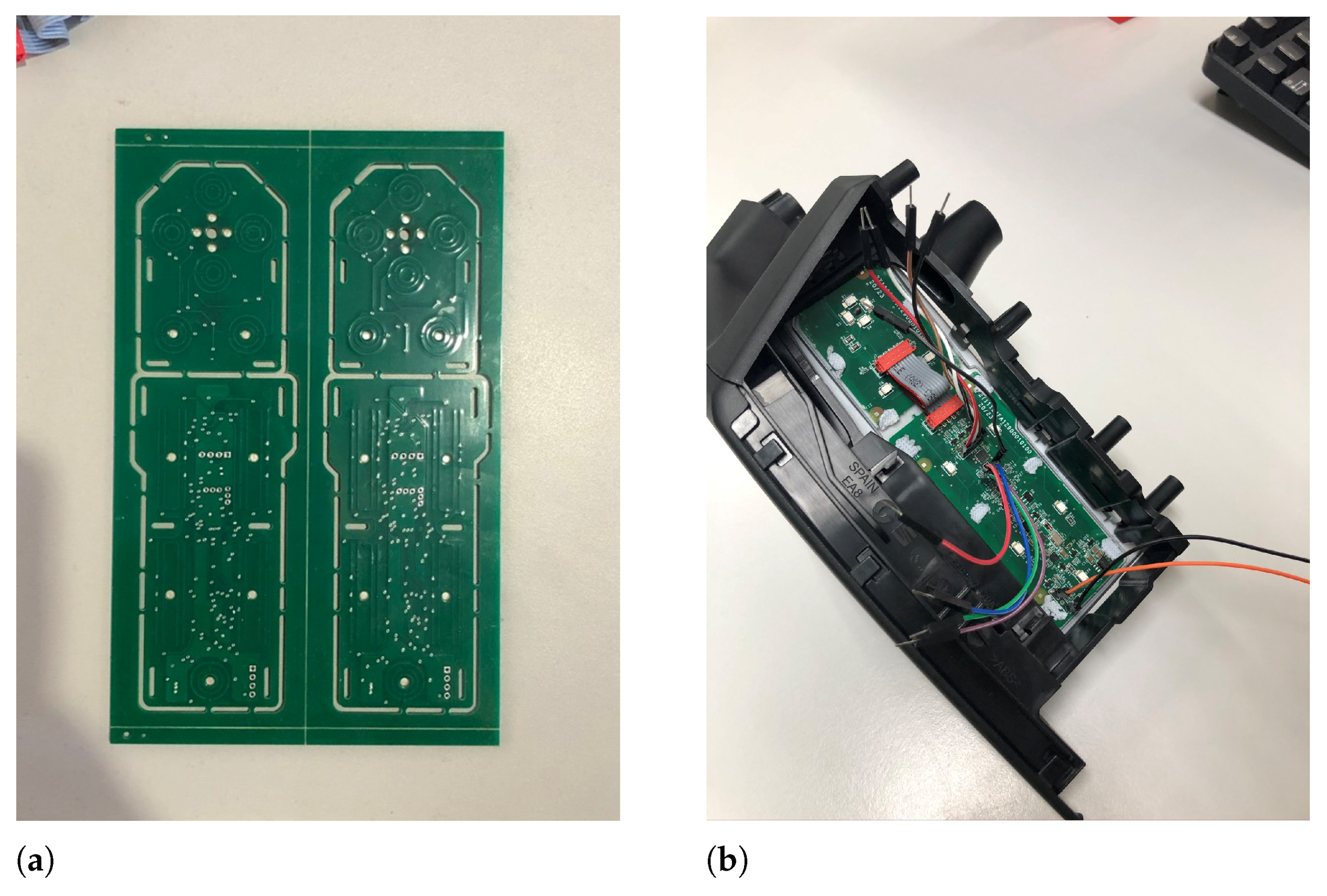
(a) PCB with 19 capacitive sensors supported. (b) The finished prototype ready to be incorporated in the automobile’s door.
Figure 18.
(a) PCB with 19 capacitive sensors supported. (b) The finished prototype ready to be incorporated in the automobile’s door.
Figure 19.
From (a–d) the figure illustrates some of the components of joystick rear-view mirrors and buttons used to open/close door windows. (a–c) depicts electronic parts of the joystick components and (d) illustrates the PCB that interacts with the contacts that are closed/opened by the button.
Figure 19.
From (a–d) the figure illustrates some of the components of joystick rear-view mirrors and buttons used to open/close door windows. (a–c) depicts electronic parts of the joystick components and (d) illustrates the PCB that interacts with the contacts that are closed/opened by the button.
Figure 20.
The functional prototype connected to the door of a real automobile manufactured in 2018. (a) depicts the new single-component touch-based polymer panel in detail, while (b) shows the panel that was integrated in the vehicle’s door, controlling the four windows (front left and right, and rear left and right) and the two rear-view mirrors.
Table 1.
Summary of the characteristics of the different technologies covered and investigated under the context of project SmartPlastic.
Table 1.
Summary of the characteristics of the different technologies covered and investigated under the context of project SmartPlastic.
| Sensor | On/Off | Panel | Robustness | Integration
(ON-OFF/Panel) | Cost
(ON-OFF/Panel) | Proj. Applicabil.
(ON-OFF/Panel) |
|---|
| Induct. | Yes | No | Good | Good/ × | High − × | −/× |
| Infra. | Yes | Yes | Good | Good/Bad | Medium − High | −/− |
| Ultra. | Yes | Yes | Good | Bad/Bad | High − High | −/− |
| Resist. | Yes | Yes | V. Good | Good /V. Good | High − Low | +/− |
| Capacit. | Yes | Yes | V. Good | V. Good /V. Good | Low − Medium | +/+ |
Table 2.
Preliminary tests to test the permissible plastic thickness (for sensor 1).
Table 2.
Preliminary tests to test the permissible plastic thickness (for sensor 1).
| Polymer | Description | Thickness
(mm) | Test
Version | Test
Number | Effectiveness | Assessment |
|---|
| PC ABS | Taroblend 66 | 0.8 | V1 | >10 | NA | Approved |
| PA6GF30 | Ultramid B3E2G6 | 0.8 | V1 | >10 | NA | Approved |
| PPTD20 | Hostacom TRC 352N | 0.8 | V1 | >10 | NA | Approved |
| PP | Sabic PHC3181 | 0.8 | V1 | >10 | NA | Approved |
| PA6 | Badamid B70S Natur | 0.8 | V1 | >10 | NA | Approved |
| PC ABS | Taroblend 66 | 1.8 | V1 | >10 | NA | Approved |
| PA6GF30 | Ultramid B3E2G6 | 1.8 | V1 | >10 | NA | Approved |
| PPTD20 | Hostacom TRC 352N | 1.8 | V1 | >10 | NA | Approved |
| PP | Sabic PHC3181 | 1.8 | V1 | >10 | NA | Approved |
| PA6 | Badamid B70S Natur | 1.8 | V1 | >10 | NA | Approved |
| PC ABS | Taroblend 66 | 2.5 | V1 | >10 | NA | Approved |
| PA6GF30 | Ultramid B3E2G6 | 2.5 | V1 | >10 | NA | Approved |
| PPTD20 | Hostacom TRC 352N | 2.5 | V1 | >10 | NA | Approved |
| PP | Sabic PHC3181 | 2.5 | V1 | >10 | NA | Approved |
| PA6 | Badamid B70S Natur | 2.5 | V1 | >10 | NA | Approved |
Table 3.
Effectiveness tests for sensor 1.
Table 3.
Effectiveness tests for sensor 1.
| Polymer | Description | Thickness
(mm) | Test
Version | Test
Number | Hits | Effectiveness | Assessment |
|---|
| PC ABS | Taroblend 66 | 2.5 | v2 | 30 | 30 | 100.00% | Approved |
| PA6GF30 | Ultramid B3E2G6 | 2.5 | v2 | 30 | 30 | 100.00% | Approved |
| PPTD20 | Hostacom TRC 352N | 2.5 | v2 | 30 | 29 | 96.67% | Approved |
| PP | Sabic PHC3181 | 2.5 | v2 | 30 | 29 | 96.67% | Approved |
| PA6 | Badamid B70S Natur | 2.5 | v2 | 30 | 29 | 96.67% | Approved |
Table 4.
Effectiveness tests for sensor 2.
Table 4.
Effectiveness tests for sensor 2.
| Polymer | Description | Thickness
(mm) | Test
Version | Test
Number | Hits | Effectiveness | Assessment |
|---|
| PC ABS | Taroblend 66 | 2.5 | v2 | 30 | 30 | 100.00% | Approved |
| PA6GF30 | Ultramid B3E2G6 | 2.5 | v2 | 30 | 30 | 100.00% | Approved |
| PPTD20 | Hostacom TRC 352N | 2.5 | v2 | 30 | 30 | 100.00% | Approved |
| PP | Sabic PHC3181 | 2.5 | v2 | 30 | 30 | 100.00% | Approved |
| PA6 | Badamid B70S Natur | 2.5 | v2 | 30 | 29 | 96.67% | Approved |
Table 5.
Effectiveness tests for sensor 3.
Table 5.
Effectiveness tests for sensor 3.
| Polymer | Description | Thickness
(mm) | Test
Version | Test
Number | Hits | Effectiveness | Assessment |
|---|
| PC ABS | Taroblend 66 | 1.8 | v2.1 | 30 | 29 | 96.67% | Approved |
| PA6GF30 | Ultramid B3E2G6 | 1.8 | v2.1 | 30 | 30 | 100.00% | Approved |
| PPTD20 | Hostacom TRC 352N | 1.8 | v2.1 | 30 | 29 | 96.67% | Approved |
| PP | Sabic PHC3181 | 1.8 | v2.1 | 30 | 30 | 100.00% | Approved |
| PA6 | Badamid B70S Natur | 1.8 | v2.1 | 30 | 30 | 100.00% | Approved |
Table 6.
Effectiveness tests for sensor 4.
Table 6.
Effectiveness tests for sensor 4.
| Polymer | Description | Thickness
(mm) | Test
Version | Test
Number | Hits | Effectiveness | Assessment |
|---|
| PC ABS | Taroblend 66 | 1.8 | v2.1 | 30 | 30 | 100.00% | Approved |
| PA6GF30 | Ultramid B3E2G6 | 1.8 | v2.1 | 30 | 30 | 100.00% | Approved |
| PPTD20 | Hostacom TRC 352N | 1.8 | v2.1 | 30 | 30 | 100.00% | Approved |
| PP | Sabic PHC3181 | 1.8 | v2.1 | 30 | 29 | 96.67% | Approved |
| PA6 | Badamid B70S Natur | 1.8 | v2.1 | 30 | 30 | 100.00% | Approved |
Table 7.
Electrical characteristics of the tested sensors.
Table 7.
Electrical characteristics of the tested sensors.
| Publisher’s Note: MDPI stays neutral with regard to jurisdictional claims in published maps and institutional affiliations. |
© 2021 by the authors. Licensee MDPI, Basel, Switzerland. This article is an open access article distributed under the terms and conditions of the Creative Commons Attribution (CC BY) license (https://creativecommons.org/licenses/by/4.0/).


