Abstract
Modern systems-on-chip (SoCs) today contain hundreds of cores, and this number is predicted to reach the thousands by the year 2020. As the number of communicating elements increases, there is a need for an efficient, scalable and reliable communication infrastructure. As technology geometries shrink to the deep submicron regime, however, the communication delay and power consumption of global interconnections become the major bottleneck. The network-on-chip (NoC) design paradigm, based on a modular packet-switched mechanism, can address many of the on-chip communication issues, such as the performance limitations of long interconnects and integration of large number of cores on a chip. Recently, new communication technologies based on the NoC concept have emerged with the aim of improving the scalability limitations of conventional NoC-based architectures. Among them, wireless NoCs (WiNoCs) use the radio medium for reducing the performance and energy penalties of long-range and multi-hop communications. As the radio medium can be accessed by a single transmitter at a time, a radio access control mechanism (RACM) is needed. In this paper, we present a novel RACM, which allows one to improve both the performance and energy figures of the WiNoC. Experiments, carried out on both synthetic and real traffic scenarios, have shown the effectiveness of the proposed RACM. On average, a 30% reduction in communication delay and a 25% energy savings have been observed when the proposed RACM is applied to a known WiNoC architecture.
1. Introduction
The evermore increasing number of cores integrated into a multiprocessor system-on-chip (MPSoC) has exacerbated the role played by the on-chip communication system [1]. Nowadays, the network-on-chip (NoC) design paradigm is considered as the most viable communication infrastructure for dealing with the performance, energy and reliability issues of many-core system architectures [2]. An NoC is composed by IP cores and switches connecting them by communication channels.
An important performance limitation in traditional NoCs arises from planar metal interconnect-based multi-hop communications, wherein the data transfer between two distant cores causes high latency and power consumption. In fact, beyond a certain length, wireless links are more energy efficient than conventional metal wires [3]. Hence, the performance improvements by using long-range wireless links will be more than that using wired links [3]. For this reason, wireless NoC (WiNoC) architectures, which use a wireless backbone upon the traditional wire-based NoC, have been recently proposed [4,5]. WiNoCs can be seen as a natural evolution of conventional NoCs to deal with the scalability issues that characterize the next generation of many-core architectures. It is foreseen that such architectures will open new opportunities in the direction of meeting critical performance and energy requirements and in the context of real-time and multimedia applications, which usually have to be supported by specific hardware resources and ad hoc management schemes.
A WiNoC is an extension of a conventional electric NoC in which, in addition to the conventional routers, there are a number of radio hubs that use the radio medium for communicating with each other. Such radio hubs are formed by a router augmented with a wireless interface. Thus, long-range communication is realized by a mixed path that involves the use of both electric links and radio communications. For instance, if a node A has to communicate with a node B, which would involve many hops in a traditional NoC, in a WiNoC, such communication can be realized as follows: (1) node A sends the packet to the closest radio hub, , through the electric NoC; (2) sends the packet to the radio hub, , closest to node B, by means of wireless communication; and (3) sends the packet to node B through the electric NoC. In this way, the number of hops needed for the communication from node A to node B can be reduced with a consequent reduction in terms of communication delay and energy consumption.
In current WiNoC implementations, due to feasibility and cost-related issues, the availability of a single radio channel is often considered [6]. That is, there can be a single transmitting radio hub at a time. For this reason, an access control mechanism for determining the radio hub authorized to use the radio media is needed.
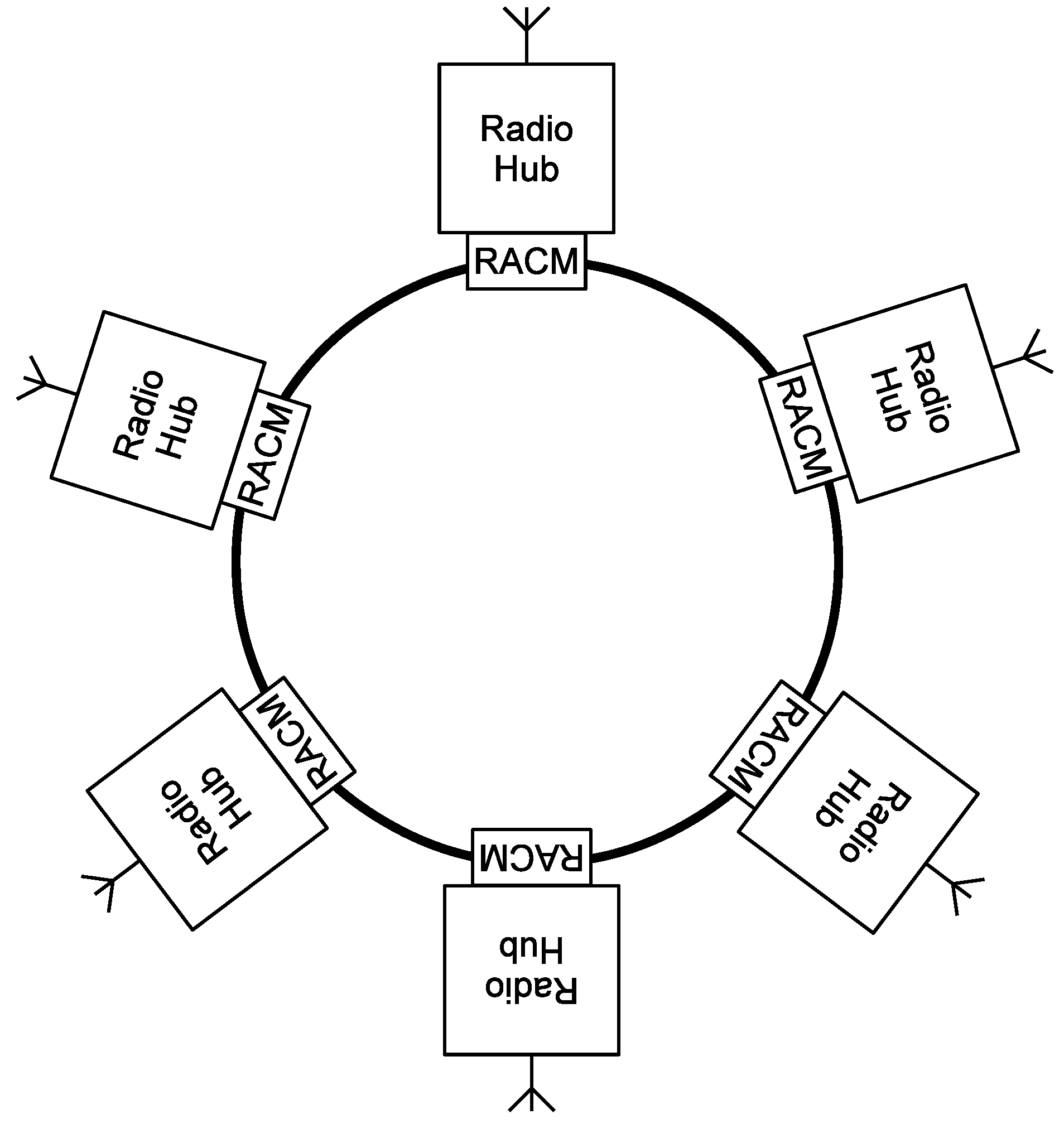
The radio access control mechanism (RACM) used in the WiNoC context has a critical impact on communication performance and power metrics. Further, its implementation must not affect the cost and power figures of the communication fabric. For this reason, in current WiNoC implementations, a simple token ring-based architecture is used for implementing the RACM [6], as shown in Figure 1. A token circulates through the radio hubs and enables the current radio hub that holds the token to use the radio medium in transmission mode for a certain amount of clock cycles. The amount of cycles assigned to each radio hub (hold cycles) is defined at design time based on the communication bandwidth requirements of the applications mapped onto the WiNoC. The ring architecture is favored for its low wiring overhead, which is important, as the radio hubs are usually placed far away from each other over the chip.
In this paper, we propose a new RACM for WiNoC architectures that allows one to improve the communication performance and power without losing the advantages of the low wiring overhead of the ring architecture. The basic idea behind the proposed RACM is to dynamically tune the hold time assigned to each radio hub by guaranteeing that the maximum token round time is below a given threshold. Experiments, carried out on both synthetic and real traffic scenarios, prove the effectiveness of the proposed RACM. As compared to the conventional RACM, the use of the proposed RACM allows one to reduce, on average, the communication delay by 30% and to save 25% of the energy.
2. Related Work
Access control is the process of mediating every requests to resources and data maintained by a system and determining whether the request should be granted or denied. Several access control mechanisms for arbitrating the use of the radio medium have been proposed in the literature in different contexts, including on-chip, off-chip or macro-world wireless networks.
In the context of radio access control mechanisms, they can be divided in two main classes, namely contention-based and TDMA (time division multiple access)-based protocols [7,8,9]. The contention-based protocols allow nodes independent access to the shared wireless medium [7,9]. In the TDMA-based protocols, the system time is divided into time slots. Each of the nodes has its own time slot assigned and may access the shared medium only in this time slot. This allows avoiding collisions, idle listening and scheduling the sleep of the transceiver, without additional overhead.
The radio access control mechanism (RACM) typically used in WiNoC architectures is based on TDMA [6,10,11,12] in which time slots are regulated by means of a token, which circulates among the transmitting stations [13]. Another peculiarity of WiNoC architectures is the number of available radio channels. Current, real WiNoC implementations are limited to the use of a single radio channel. In fact, implementing multiple radio channels, in current technologies, would be infeasible due to the area overhead of the antennas (multiple channels requires multiple antennas). However, when, in the future, multiple radio channels in the same chip will be available, the proposed RACM can be still applied. In fact, multiple channels results in multiple rings in which a different instance of the RACM can be used in each of them. In the current literature, several studies have analyzed how performance and energy metrics would scale with the number of radio channels. For instance, in [14], a multi-channel WiNoC system based on UWB transceivers is proposed. The authors in [6] have presented a mm metal zigzag antenna for designing a mm-wave WiNoC architecture and then extended this single channel mWNoC design to a multichannel mWNoC. The authors in [15] have proposed a WiNoC system by using sub-THz antennas deposited in a polyimide layer in a 32-nm CMOS process. Such an infrastructure provides distinct channels in the frequency range of 100–500 GHz. Carbon nanotube (CNT) antennas have been proposed to achieve the terahertz frequency range [16]. The CNT antennas can provide much higher communication data rates due to their small size, resulting in ultra-low area overhead. Using such technology, non-overlapping wireless channels, each with a 10-Gb/s bandwidth and 0.33 pJ/bit of energy, can be achieved [12].
3. Radio Access Control Mechanism
The radio medium can be accessed by a single radio hub at a time. Thus, a radio access control mechanism (RACM) must be used for avoiding multiple radio hubs having access to the radio medium simultaneously. A token-based approach is usually used for implementing the RACM. Basically, a token is passed through every radio hub, enabling the radio hub owning the token to use the radio medium for a maximum number of clock cycles. Such a token-based mechanism can be implemented by means of a ring network topology connecting the radio hubs, as shown in Figure 1.
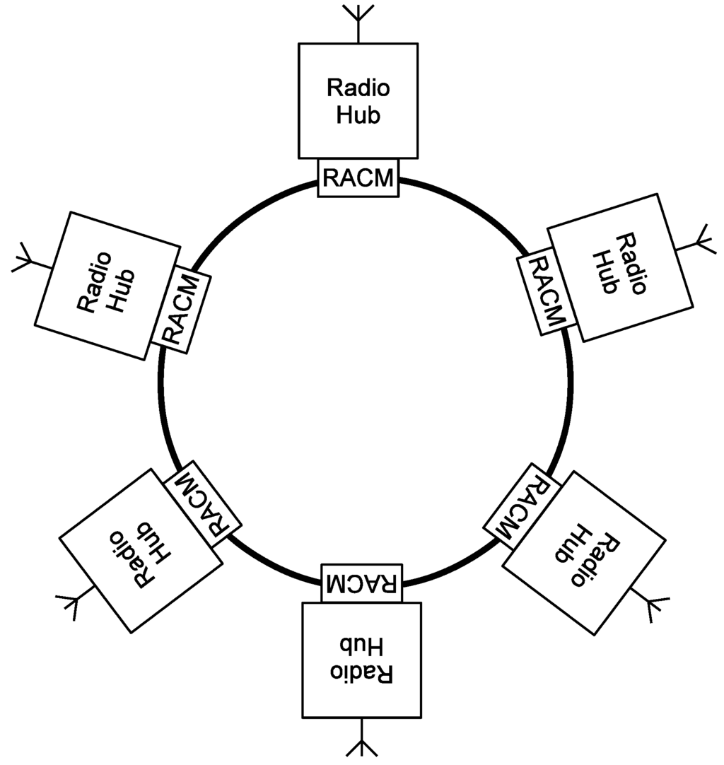
Figure 1.
Conventional ring-based topology for implementing the radio access control mechanism in a wireless network-on-chip (WiNoC).
Figure 1.
Conventional ring-based topology for implementing the radio access control mechanism in a wireless network-on-chip (WiNoC).
Although different implementations of the RACM are possible, we focus on distributed architectures implemented by a ring network topology. The main motivation of this choice is related to their suitability for being used in the on-chip context, in which silicon area (i.e., cost) and energy consumption are inalienable design metrics. In fact, a ring network topology requires the minimum number of short point-to-point links among the radio hubs, as compared to other topologies or a centralized control structure, which would bring to the wiring congestion issues and complications during placement and the routing phases of the design flow.
3.1. Conventional RACM
The conventional RACM used in WiNoCs [13] can be implemented by means of a simple finite state machine, whose behavior, for a generic node of the ring, is summarized by Algorithm 1. The generic node of the ring has three inputs and two outputs. The radio hub uses input to request the access to the radio channel. If the ring node owns the token, the output is asserted, and the radio hub is allowed to use the radio medium in transmission mode. The output is kept high, as long as the input is high, but for a maximum number of cycles that does not exceed a certain threshold, referred to as the maximum hold cycles, . When the input is unset or cycles are elapsed, the token is passed to the next node.
| Algorithm 1 Conventional radio access control mechanism (RACM) implemented by a node of the ring. |
| Require: , , Ensure: ,
|
Thus, if we indicate with the maximum hold count for the i-th node of the ring, the generic j-th radio hub is guaranteed to have granted the access to the radio medium for cycles every cycles in the worst case. The main drawback of this approach is that the generic i-th radio hub is limited to using the radio medium for cycles at most, even if the rest of the radio hubs do not consume their assigned budget of clock cycles (). Such a situation can strongly affect the performance of the network, as will be shown in the experimental section. Please note that the and registers of each radio hub are initialized during the reset period. Specifically, the register is initialized with zero, whereas is initialized with true for the with ID 0 and with false for the other radio hubs.
Another conventional RACM does not use the hold counter and releases the token only when all of the flits of the packet have been transmitted. We will refer to this conventional RACM as conventional RACM without holding.
In the next subsection, we will present a novel RACM that dynamically tunes the based on the actual communication profile.
3.2. Proposed RACM
In the conventional RACM, the maximum number of cycles assigned to the generic i-th radio hub for using the radio medium when it owns the token, , is statically determined and remains the same, irrespective of the traffic conditions. In practical situations, however, there are radio hubs that do not use their cycles entirely, whereas there are others that entirely use their cycles. Such unbalanced utilization can be seen as an opportunity for performance improvement. Thus, the basic idea of the proposed RACM is redistributing the unused clock cycles among the radio hubs that have entirely used their . More precisely, let us indicate with the number of cycles that the radio hub i has held the token in the current round. Thus, the number of unused cycles by radio hub i in the current round is . In the proposed RACM, the total number of unused cycles, , is redistributed among the radio hubs in proportion to the utilization of their in the previous round.
The pseudocode implementing the proposed RACM is summarized by Algorithm 2. In this case, the token holds a set of information that is updated and used by every RACM module in the ring. In particular, stores the total number of unused cycles in the previous round. is used for accumulating the unused cycles while the token circulates through the RACM modules. stores the number of cycles for which the radio hub i held the token in the previous round (i.e., the utilization of the radio medium). Finally, stores the maximum utilization observed at the previous round. As can be observed, the S, and fields of the token are initialized during the reset period and when the token completes a round, i.e., when the token returns to the RACM module with zero (Lines 3–5). Before passing the token to the next RACM module (Lines 17 and 23), the U and fields of the token are updated with the current utilization and with the total number of unused cycles up to the current radio hub, respectively. Differently from Algorithm 1, here, the current radio hub can hold the token for a maximum number of cycles, which depends on its utilization and on the total number of unused cycles in the previous round (Line 16). Please note that, like for the conventional RACM, the generic j-th radio hub is guaranteed to have granted the access to the radio medium every cycles in the worst case.
| Algorithm 2 Proposed RACM implemented by a node of the ring. |
| Require: , , Ensure: ,
|
3.3. Synthesis of the RACM Module
Figure 2 shows the interface of the module implementing the proposed RACM. It is connected to the radio hub with the conventional three signals, namely, , and . The signal is asserted from the radio hub when it wants to access the radio medium. As soon as it gets the grant, it asserts the signal, until it has something to transmit and the signal is set. The RACMs are connected to each other by means of signals S, , and U, which correspond to the fields of the token, as discussed in Section 3.2. Specifically, S encodes the total number of unused cycles in the previous round. encodes the number of unused cycles in the current round up to the current RACM module. encodes the maximum utilization (in terms of cycles) observed at the previous round. Finally, U encodes the number of cycles for which each radio hub has held the token in the previous round. Both the conventional and proposed RACM modules have been designed in VHDL, synthesized and evaluated with Synopsys Design Compiler and mapped on a 28-nm CMOS standard cell library from TSMC. An operating clock frequency of 1 GHz has been considered. For the proposed RACM, the S, , and U signals have been considered eight bits wide, which results in a limit of 256 clock cycles for the maximum hold count ( in Algorithm 2).
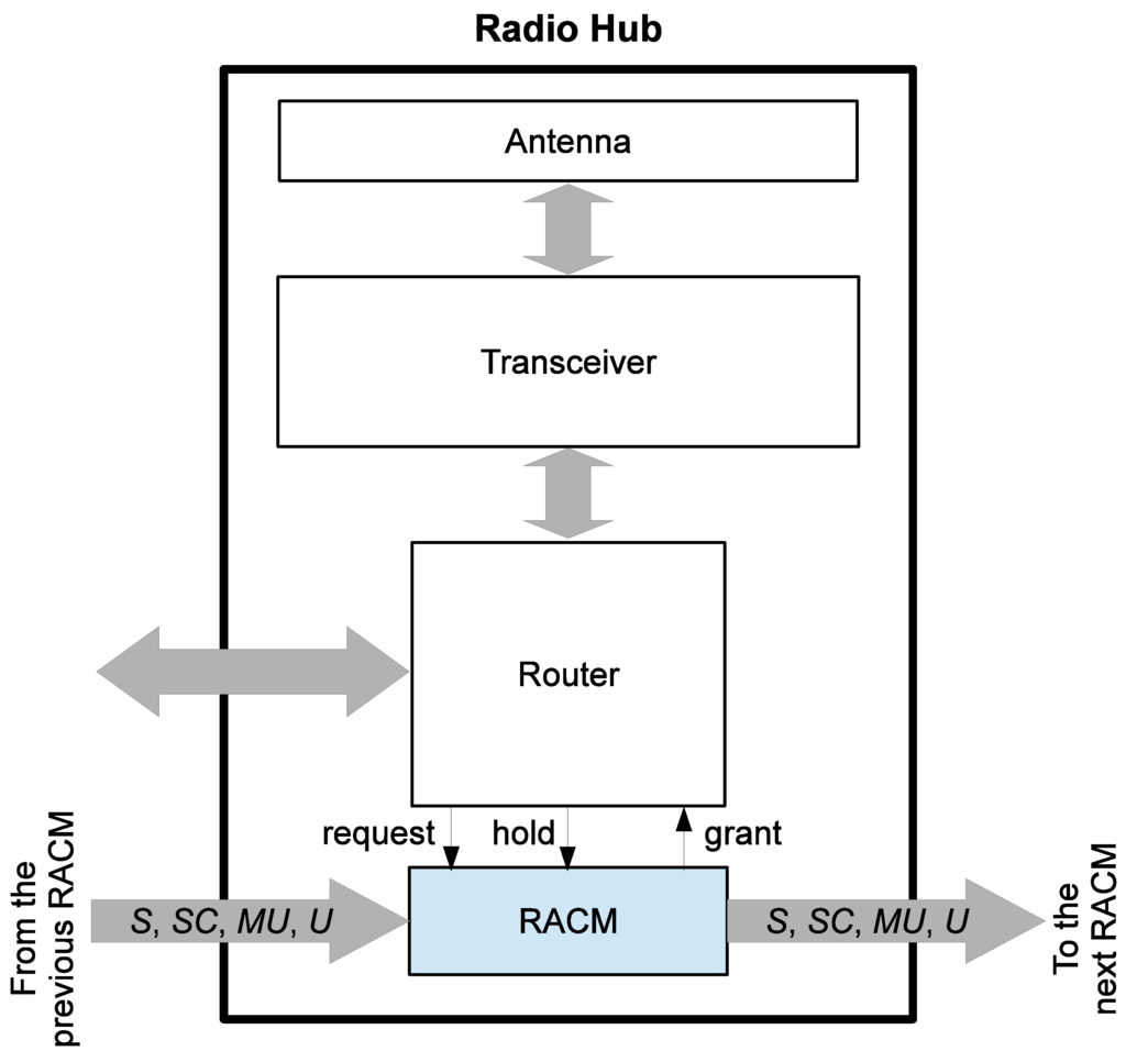
Figure 2.
Interface of the proposed RACM module.
Figure 2.
Interface of the proposed RACM module.
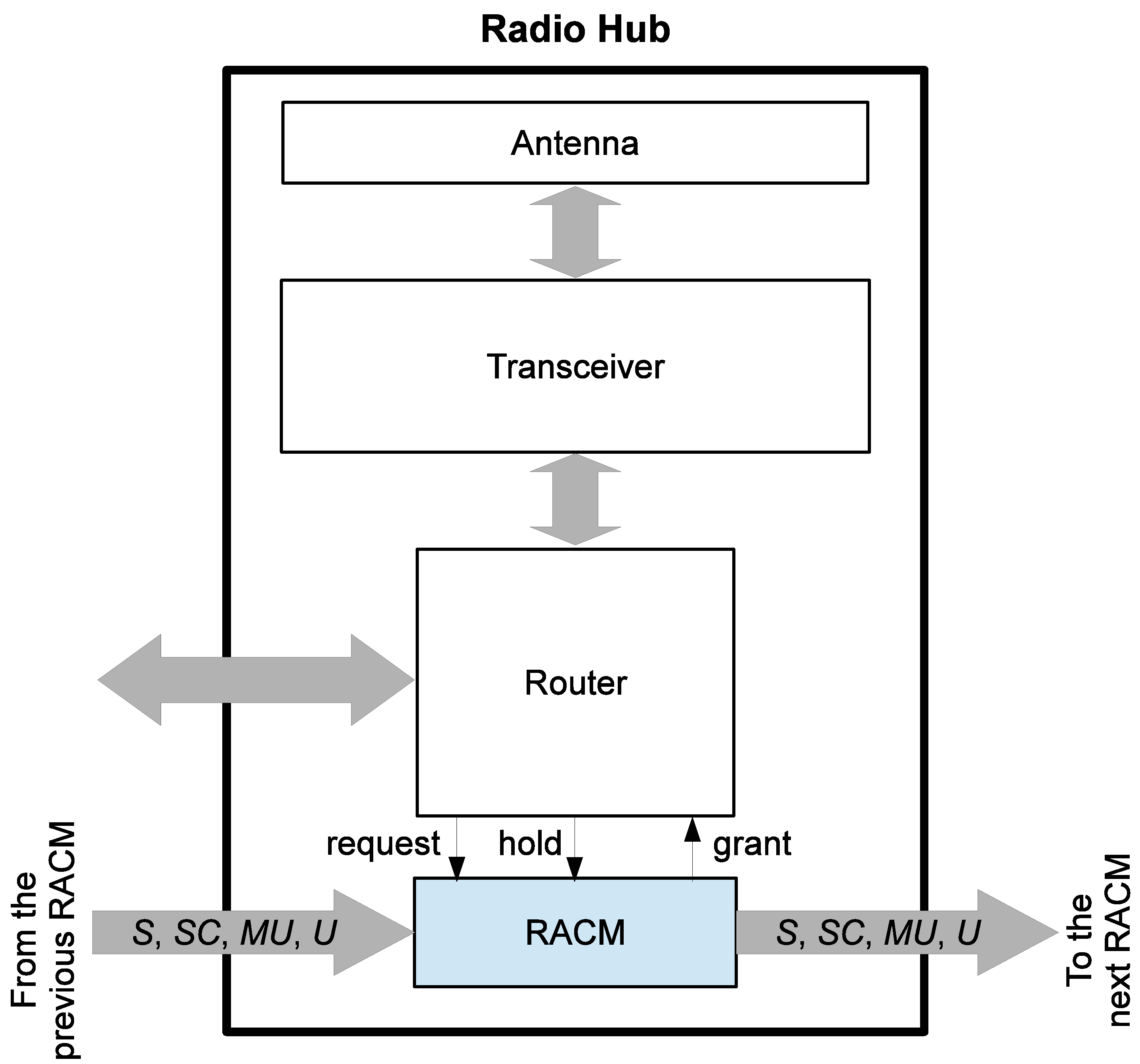
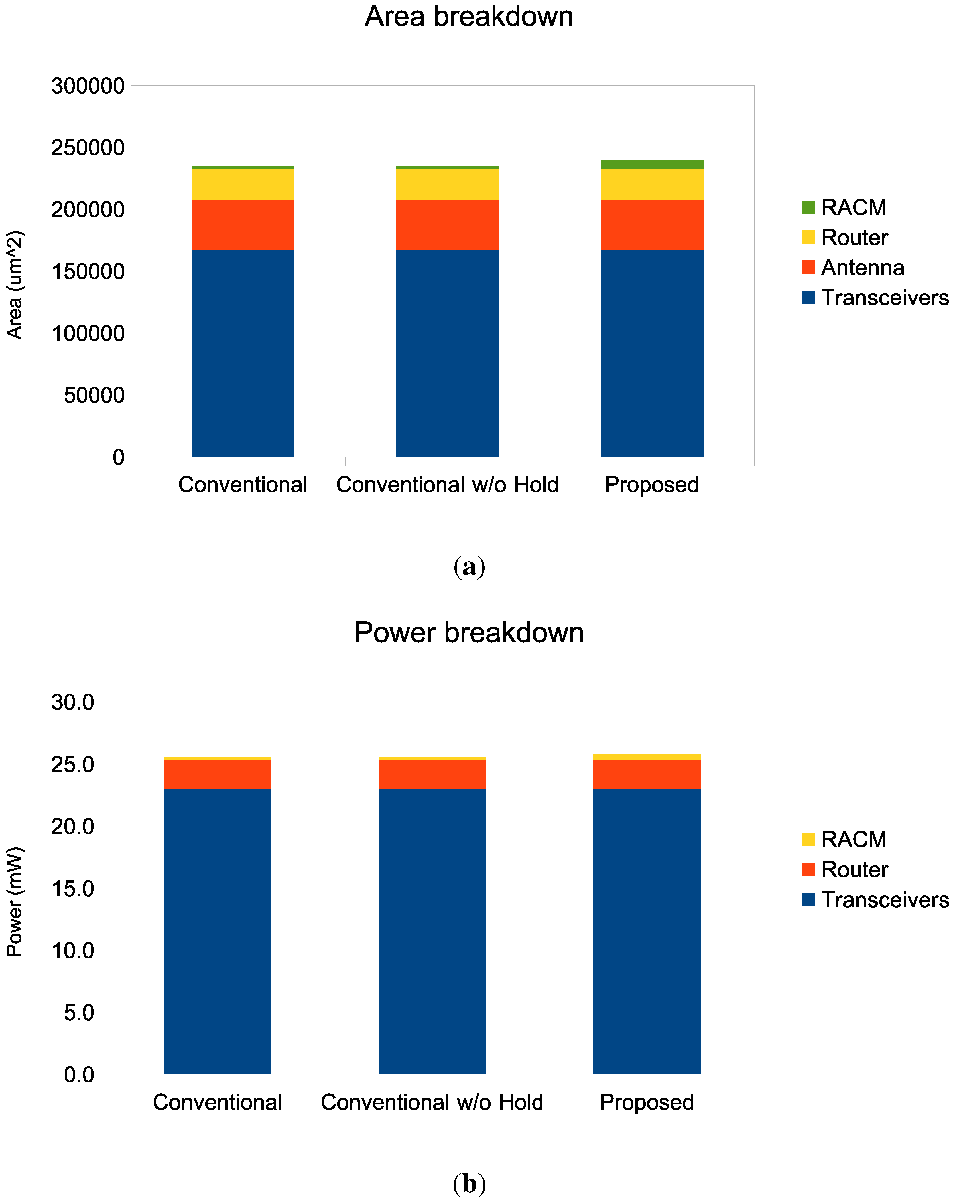
Figure 3 shows the area and power breakdown of the radio hub implementing the conventional (with and without hold) and the proposed RACM. As can be observed, the contribution of the RACM module, both in terms of silicon area and power, is negligible compared to the transceiver and the router. In fact, the RACM module accounts for less than 1% of the total radio hub area and power, and its contribution increases to about 3% when the proposed mechanism is used. However, as will be discussed in the Experiments Section, even if the proposed RACM increases the total power of the radio hub, the total communication energy decreases due to the improvement of the performance metrics.
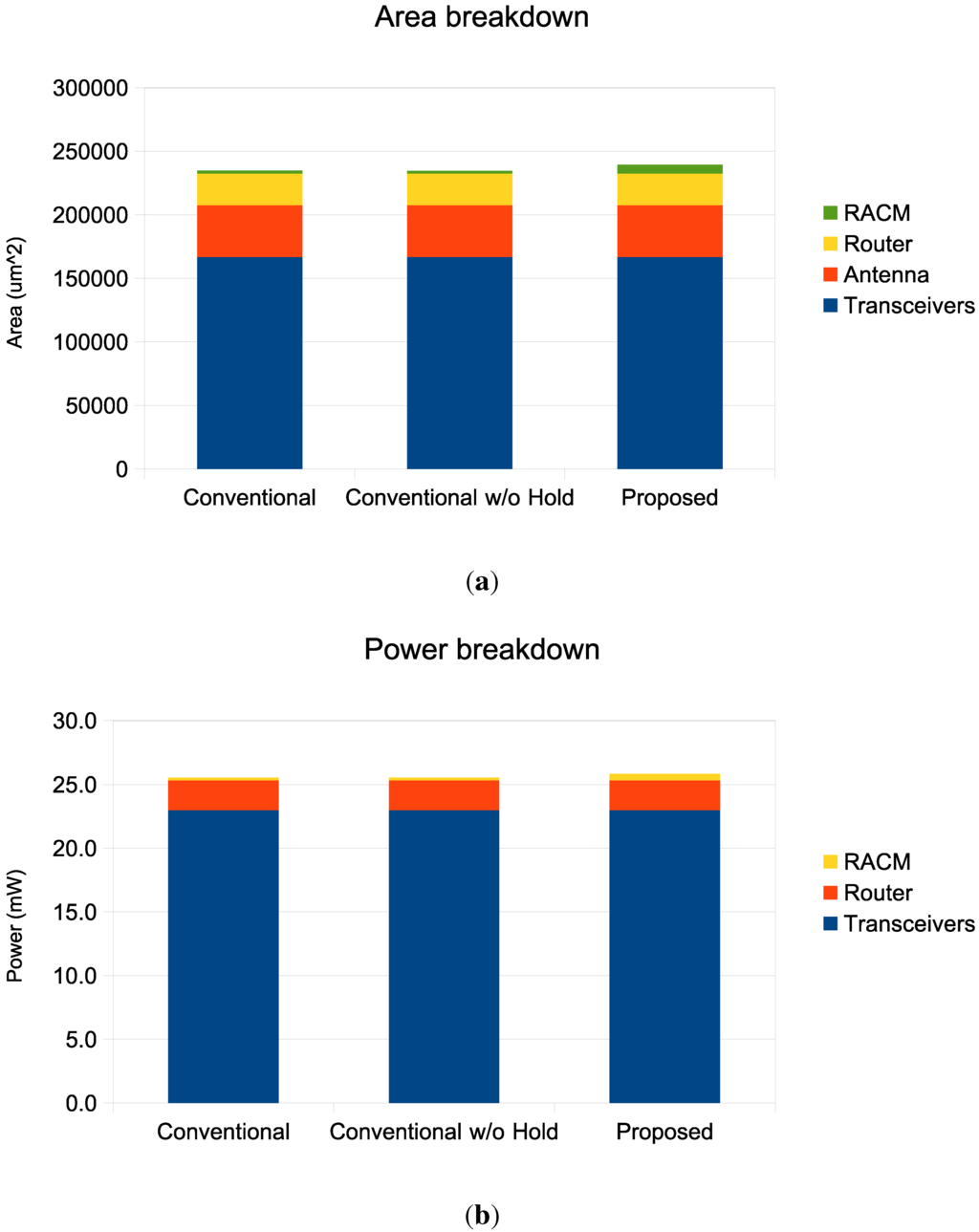
Figure 3.
Area (a) and power (b) breakdown of the radio hub.
Figure 3.
Area (a) and power (b) breakdown of the radio hub.
4. Experiments
In this section, we compare the proposed RACM with the conventional RACM. We implemented the proposed mechanism in an extended version of Noxim [17], which supports wireless communications and iWise64 architecture [18], assuming a single radio channel. Noxim is a cycle-accurate NoC simulator that allows one to estimate power and performance figures. The basic elements that form the WiNoC, namely routers, radio hubs, network interfaces and links, have been modeled in VHDL, synthesized and mapped on a 28-nm CMOS standard cell library from TSMC. The Synopsys Design Compiler has been used for extracting power figures for different configurations and different utilization factors. The energy dissipated by wireline links has been obtained through HSPICE simulations taking into consideration the length and layout of the wireline links.
In the analysis, a WiNoC architecture implemented into a silicon die has been considered. A zigzag antenna has been accurately modeled and characterized with Ansoft HFSS [19] (High Frequency Structural Simulator). HFSS is a leading commercial finite element method (FEM) field solver that simulates 3D structures and produces S-parameters and radiation patterns. We considered a high resistivity SOI with a substrate thickness of and for the oxide (SiO). The antennas are situated at an elevation of from the substrate, compatible with the guidelines reported in [20] for reducing the interference with others metal structures ([20] demonstrates that the interference due to other metallic structures is negligible by following such rules). The zigzag antenna has a thickness of and an axial length of for operating at 60 GHz. From HFSS simulation, we obtain the scattering parameters used for computing the Friis formula and then for calculating the attenuation introduced by the wireless medium. The detailed description of the transceiver circuit is out of the scope of this paper. However, the transceiver was designed in [6].
The aforementioned data have been used for back-annotating the NoC simulator in such a way to obtain power and energy figures. The conventional and the proposed RACMs are compared under both synthetic traffic scenarios and using communication traces extracted from the execution of SPLASH-2 benchmarks [21].
Figure 4 shows the average communication delay versus packet injection rate (pir) for a 64-node WiNoC architecture under a uniform traffic scenario and a random packet size ranging from 4 to 16 flits. The average packet delay is the average of the delays experienced by the packets during the simulation. The packet delay is computed by measuring the difference of the clock cycle in which the packet is generated and injected into the local buffer of the source router and the clock cycle in which the tail flit of the packet is received from the destination node. Let be the delay experienced by the i-th packet and N the total number of injected packets. Then, the average packet delay is . We consider five different values (1, 2, 4, 8 and 16 clock cycles). As can be observed, for a given pir value, when the proposed RACM is used, the average communication delay decreases. In this experiment, the packets’ sizes are randomly generated between two and 16 flits. The average delay improves as increases, and no relevant improvements are observed when is greater than eight clock cycles. This is due to the fact that, on average, eight clock cycles are enough for a radio hub to drain a packet. Thus, as decreases, the probability of a radio hub interrupting the transmission of the flits of a long packet increases. This is because the radio hub has to pass the token as soon as it consumes all of its assigned clock cycles (i.e., clock cycles in the case of the conventional RACM and a variable number of cycles, , in the case of the proposed RACM). Then, the radio hub has to wait again for the token to finalize the transmission of the packet. Now, recalling that the communication delay is the average number of clock cycles elapsed from the time in which the header flit of the packet is injected into the network to the time in which the tail flit of the packet is received by the destination core, interrupting the transmission of a packet has a strong impact on the communication delay. The possibility of dynamically and selectively tuning the of any radio hub based on the current traffic condition provided by the proposed RACM allows one to dramatically improve the overall performance of the network.
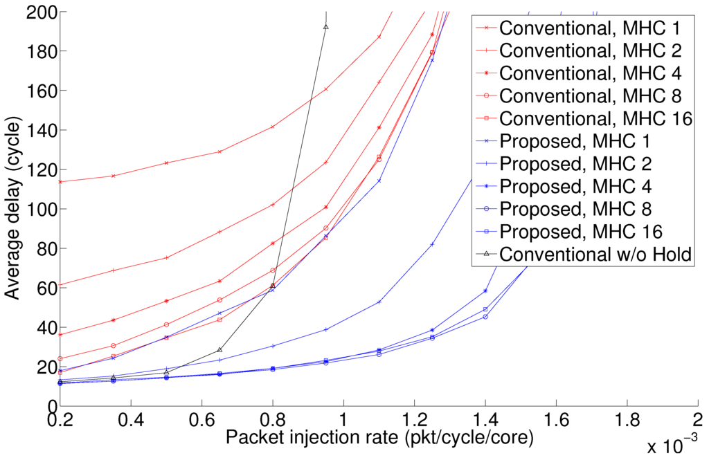
Figure 4.
Average communication delay versus the packet injection rate (pir) under a uniform traffic scenario.
Figure 4.
Average communication delay versus the packet injection rate (pir) under a uniform traffic scenario.
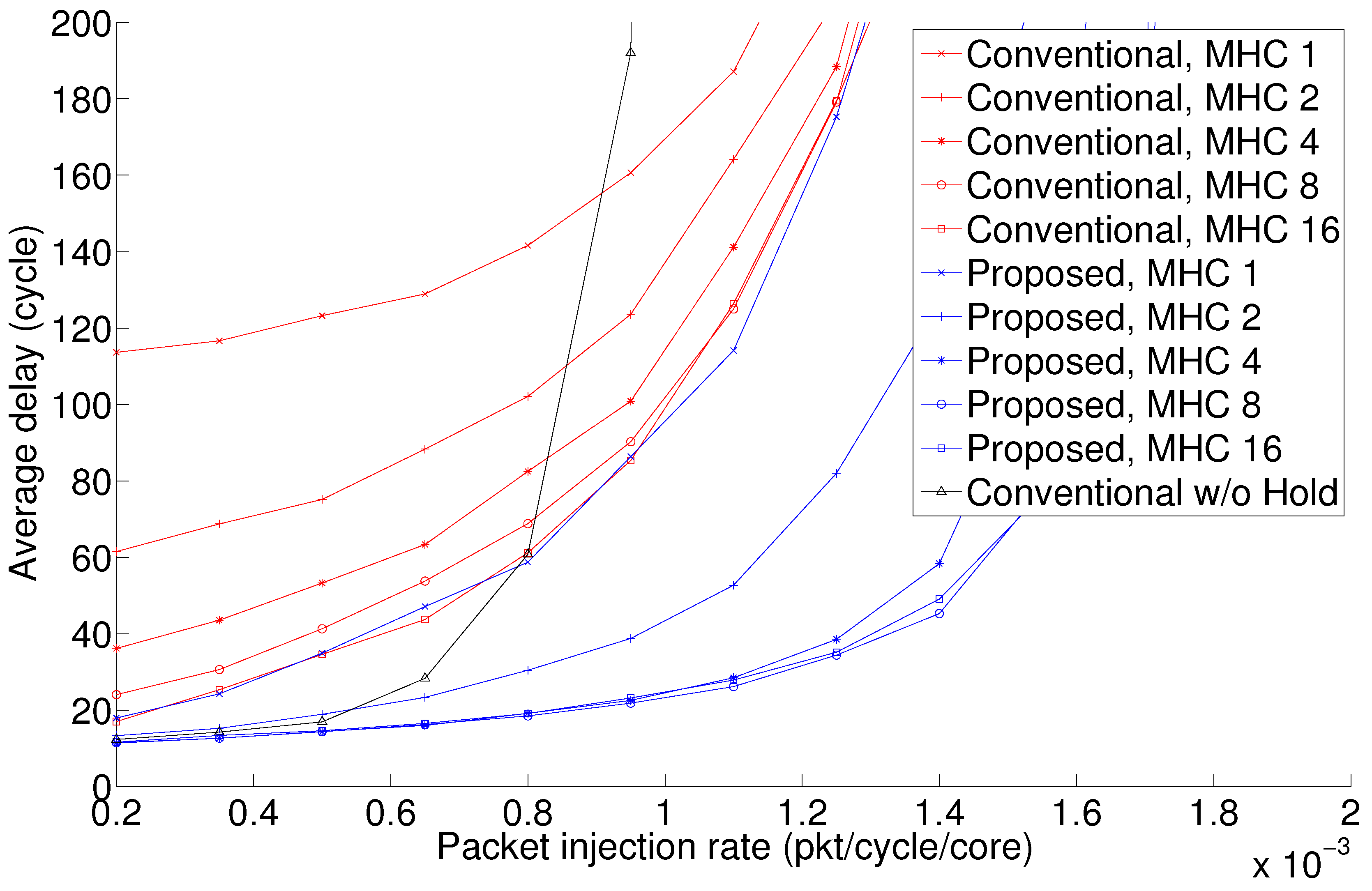
Figure 4 also shows the performance results when the conventional RACM without holding is used. As can be observed, for low packet injection rates, it outperforms the conventional RACM. However, as soon as the pir increases, the communication latency quickly increases, and the saturation point is reached before compared to the case in which the other RACMs are used. Such a behavior can be explained as follows. In a low-traffic condition, the fact that a radio hub keeps the token reserved for the entire duration of the transmission of the packet (irrespective of the packet size) does not affect the token waiting time of the other radio hubs, since the contention for the use of the radio medium is low. As soon as the injection load increases, the number of requests of the radio hubs for accessing the radio medium increases, and the token waiting time increases, as the radio hub that owns the token is not forced to release it.
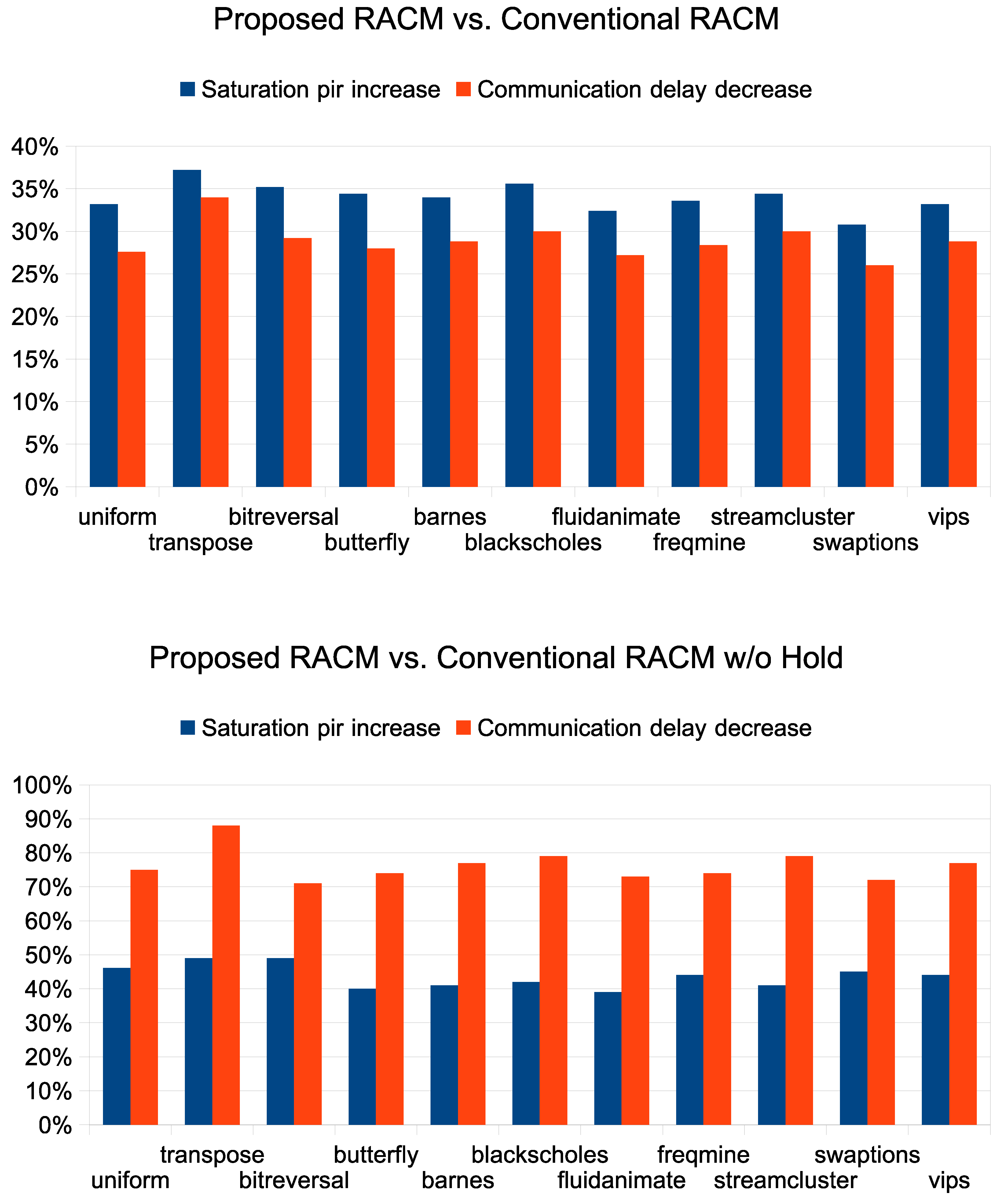
Figure 5 summarizes the performance improvement obtained when the proposed RACM is used. Two performance metrics are considered as follows: the percentage increase of the saturation pir and the percentage decrease of the average communication delay measured at a pir value corresponding to 50% of the bisection bandwidth for that specific traffic scenario. The saturation pir is defined as the maximum pir value above which the variation of the throughput deviates from its linear behavior. For all of the experiments, we consider four-flit input buffers for routers and eight-flit input buffers for routers with the wireless interface (i.e., the radio hubs). For the sake of clarity, we consider the case with . As can be observed, as compared to the conventional RACM, the proposed RACM allows one to obtain relevant performance improvement. For the considered traffic scenarios, on average, the saturation pir increased by 34% and the communication delay decreased by 29%. As expected, even higher performance improvements are observed when the proposed RACM is compared with a conventional RACM without holding. On average, the saturation pir increased by 44% and the communication delay decreased by 76%.
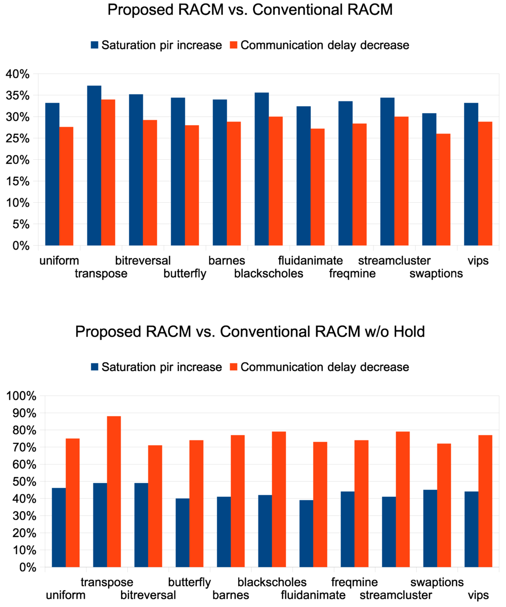
Figure 5.
Percentage increase of the saturation pir and percentage decrease of the average communication delay when the proposed RACM is used.
Figure 5.
Percentage increase of the saturation pir and percentage decrease of the average communication delay when the proposed RACM is used.
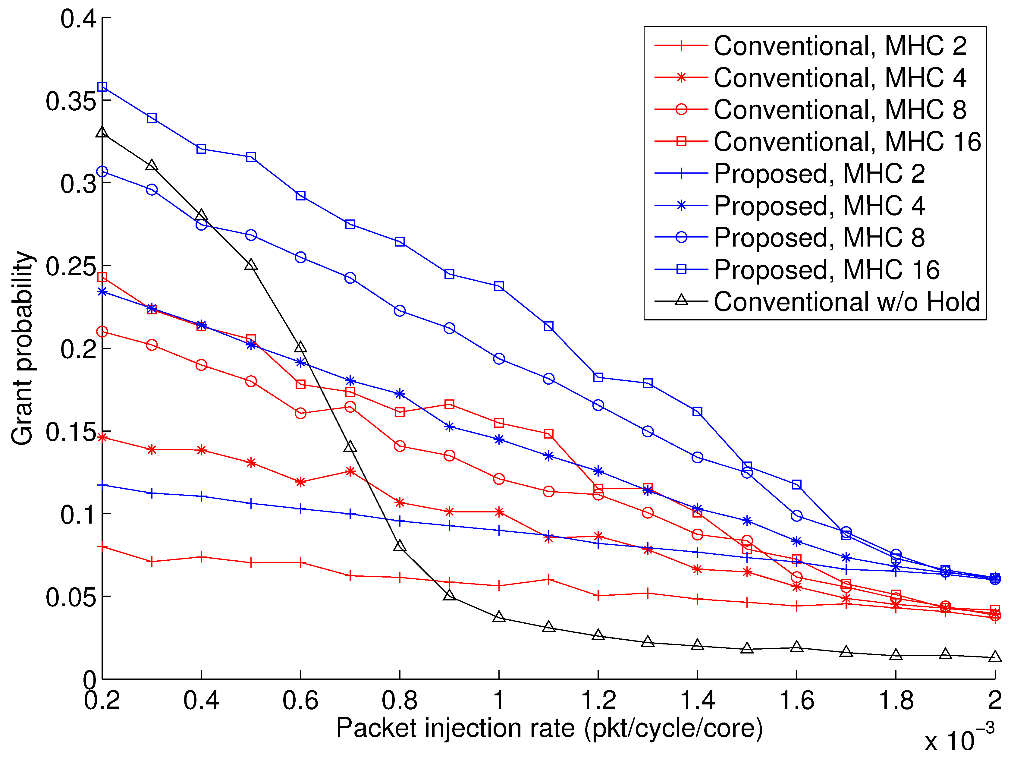
The effectiveness of the proposed RACM can also be assessed by observing the grant probability, that is the probability that a generic radio hub requests the access to the radio medium and the request is granted, or it has been already granted the access to it, and it can hold the access for additional cycles. Figure 6 shows the grant probability for different packet injection rates under uniform traffic. The grant probability represents the fraction of times a radio hub requires the access to the radio medium and the access is granted. As can be observed, for a given pir, when the proposed RACM is used, the probability of a radio hub being granted its request to access the radio medium or holding the radio medium for additional cycles is higher than that observed when the conventional RACM is used. The same figure shows the grant probability when the conventional RACM without holding is used. In this case, by grant probability it is meant the probability that a generic radio hub requests the access to the radio medium and the request is granted. As already observed in Figure 4 for a low injection rate, the conventional RACM without holding performs well, and this is also reflected by its grant probability. However, its performance quickly degrades as soon as the injection rate increases. In fact, since the radio hub that holds the token is not forced to release the token until it has not exhausted the transmission of the packet, the other radio hubs ready for transmission will experience a high waiting time. Based on this, the grant probability rapidly decreases as the pir increases.
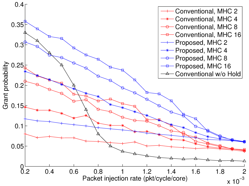
Figure 6.
Grant probability under uniform traffic.
Figure 6.
Grant probability under uniform traffic.
As discussed in Section 3.3, the proposed RACM introduces an overhead, both in terms of area and energy, as the implementation of the mechanism requires additional logic, which is not present in the conventional RACM. However, although the average power dissipated by the proposed RACM module is higher than that of the conventional RACM, the reduction of the average communication delay (as shown in Figure 5) results in a reduction of the execution time with a consequent reduction of the total energy consumption. Figure 7 shows the communication energy savings when the proposed RACM is used. Energy figures have been computed without taking into account the energy contribution of the cores, i.e., only communication energy is considered. As can be observed, on average, 25% of the energy savings is obtained when the proposed RACM is used, and this goes up to 32% when compared to the conventional RACM without holding. Both the proposed RACM and the conventional RACM have been applied considering a radio hub implementing the transceiver proposed in [22] and also used in [18]. For this, we estimated a power consumption of 7 mW to 23 mW for the minimum and maximum transmitting power (depending on the physical distance between the source and the destination node), respectively. These correspond to energy per bit ranging from 0.42 to 1.4 pJ/bit.
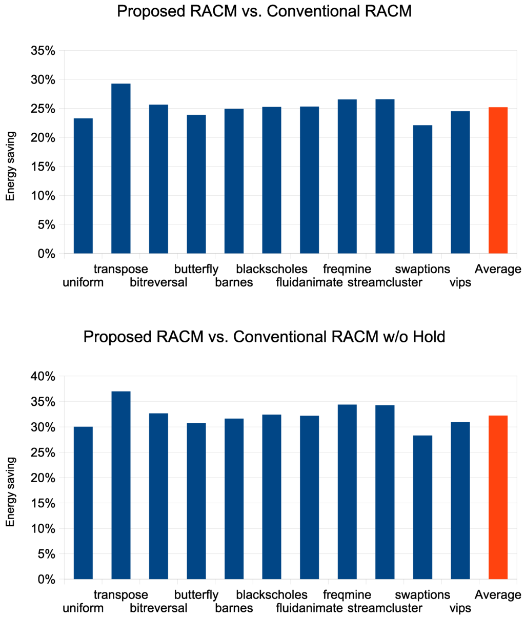
Figure 7.
Communication energy savings when the proposed RACM is used.
Figure 7.
Communication energy savings when the proposed RACM is used.
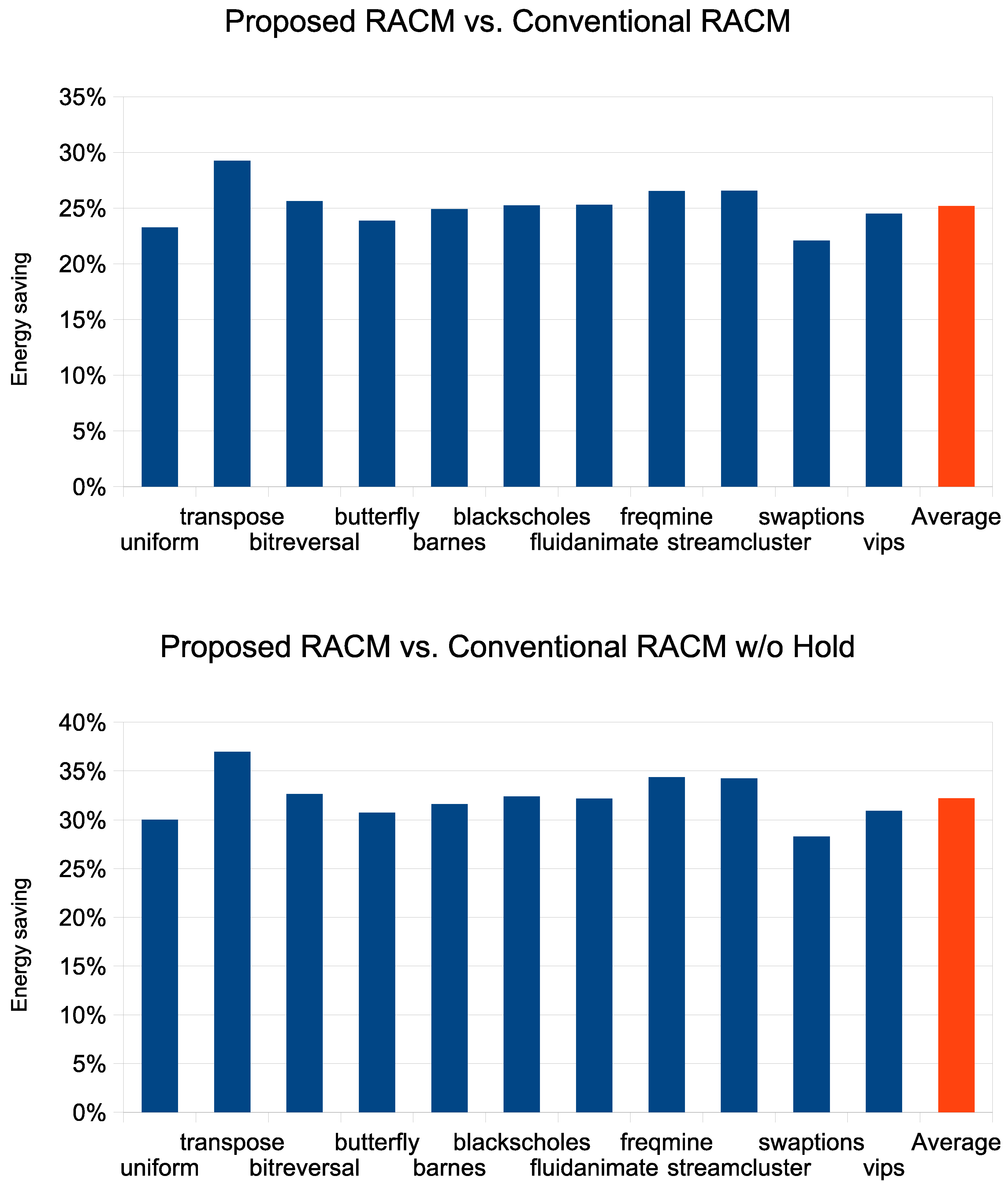
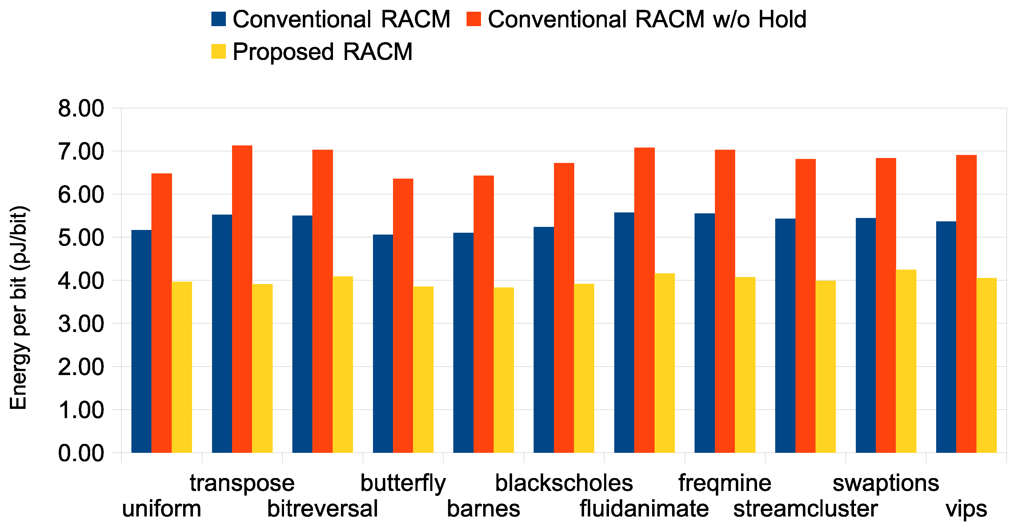
Figure 8 shows the measured energy per bit under different traffic scenarios in the two cases in which the traditional RACM is used and when it is replaced by the proposed RACM. As can be observed, the use of the proposed RACM results in significant energy per bit savings for all of the benchmarks considered in the experiments.
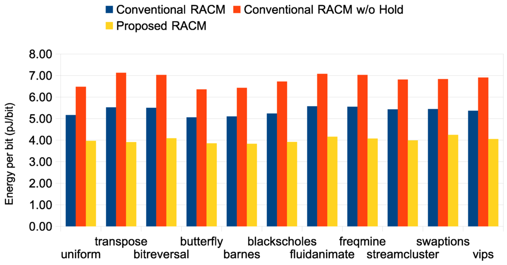
Figure 8.
Measured energy per bit when the traditional RACM and the proposed RACM are used.
Figure 8.
Measured energy per bit when the traditional RACM and the proposed RACM are used.
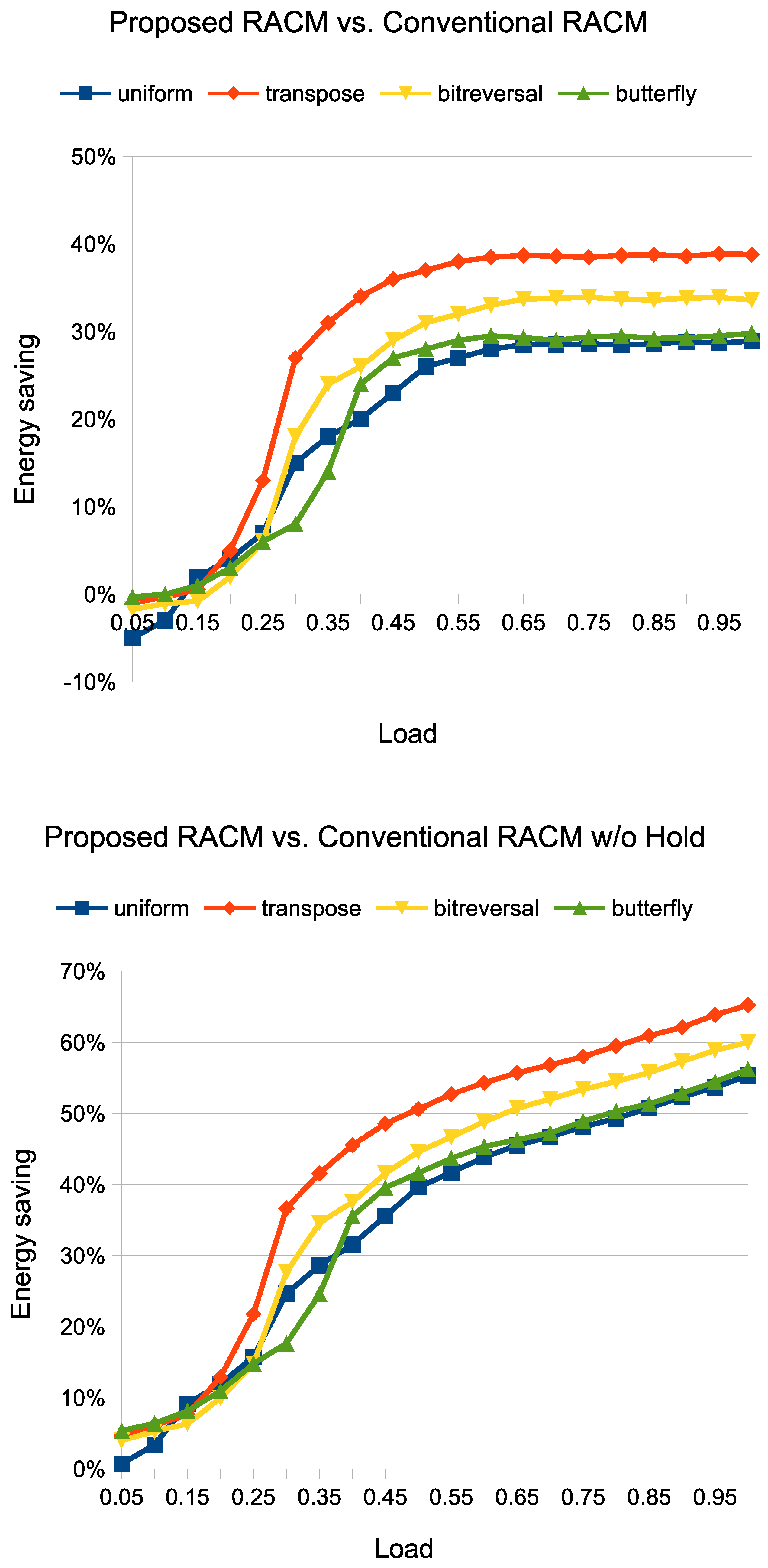
Finally, Figure 9 shows the energy savings for different network loads. We considered the synthetic traffic scenarios (uniform, transpose, bit-reversal and butterfly), and for each of them, we measured the energy consumption as the injected load increases. As can be observed, for a low injection load, the conventional RACM is more energy efficient than the proposed RACM (negative values of energy savings). This is due to the fact that for low loads, the access to the shared radio medium does not represent a bottleneck for communication latency, as the level of contention for it is low. Thus, since the energy overhead of the proposed RACM is not compensated by the performance improvement (which is limited at low loads), the percentage of energy savings is negative. Things change drastically as soon as the traffic load increases. In fact, since the proposed RACM shifts the saturation load, the performance improvement becomes dominant with a consequent energy savings. Such an effect is even more evident when the proposed RACM is compared with the conventional RACM without holding. As can be observed, as soon as the load increases, the energy savings increases much more quickly than the previous case, due to the performance limitation exhibited by the conventional RACM without holding.
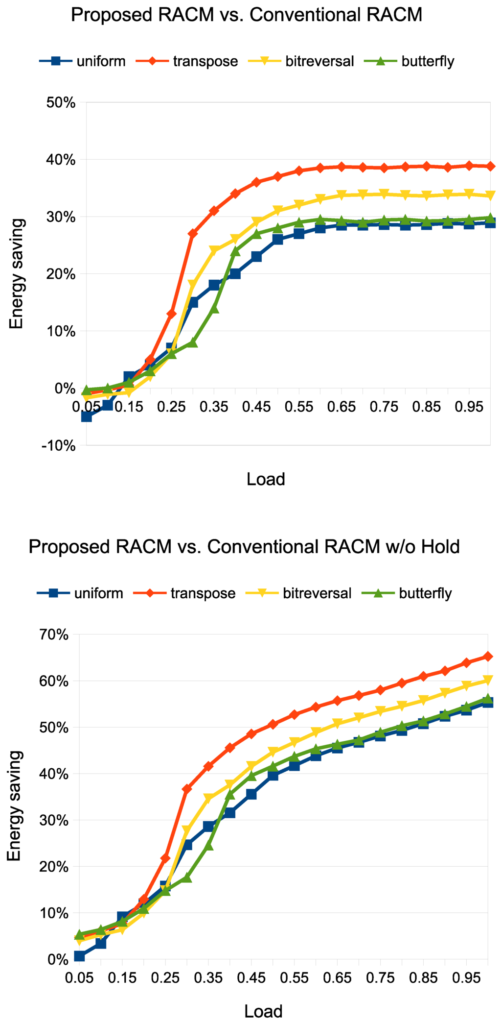
Figure 9.
Energy versus injected load.
Figure 9.
Energy versus injected load.
5. Conclusions
In a WiNoC architecture, the routers augmented with a wireless interface, namely radio hubs, can transmit over a single radio channel (or over a limited set of radio channels, typically ranging from one to four) [6,14,18]. Thus, for each radio channel, a radio access control mechanism (RACM) is used for arbitrating the access to the radio medium. Generally, the RACM is implemented by means of a token-based mechanism. Basically, a token circulates through the radio hubs and enables the radio hub owning the token to use the radio medium for a certain number of clock cycles. In this paper, we have presented a novel RACM that allows one to improve the utilization of the radio medium compared to the conventional RACM implemented in current WiNoCs proposed in the literature. The basic idea behind the proposed RACM is based on distributing the unused clock cycles by the radio hubs in the previous round among all of the radio hubs proportionally to how they utilized the radio medium in the previous round. Experimental results, carried out on both synthetic and real traffic scenarios, have shown the effectiveness of the proposed RACM, both in terms of performance and energy consumption. On average, a 30% reduction in communication delay and a 25% energy savings has been observed under both synthetic and real traffic scenarios.
Author Contributions
Maurizio Palesi was responsible for authoring this paper, the design and test of the proposed mechanism, and the experimental analysis. Mario Collotta, Andrea Mineo and Vincenzo Catania, review the proposed mechanism and edit this paper.
Conflicts of Interest
The authors declare no conflict of interest.
References
- Manferdelli, J.L.; Govindaraju, N.L.; Crall, C. Challenges and opportunities in many-core computing. Proc. IEEE 2008, 96, 808–815. [Google Scholar] [CrossRef]
- Ivanov, A.; Micheli, G.D. The network-on-chip paradigm in practice and research. IEEE Des. Test Comput. 2005, 22, 399–403. [Google Scholar] [CrossRef]
- Chang, K.; Deb, S.; Ganguly, A.; Yu, X.; Sah, S.P.; Pande, P.P.; Belzer, B.; Heo, D. Performance evaluation and design trade-offs for wireless network-on-chip architectures. ACM J. Emerg. Technol. Comput. Syst. 2012, 8, 1–23. [Google Scholar] [CrossRef]
- Zhao, D.; Wang, Y. Sd-mac: Design and synthesis of a hardware-efficient collision-free qos-aware mac protocol for wireless network-on-chip. IEEE Trans. Comput. 2008, 57, 1230–1245. [Google Scholar] [CrossRef]
- Deb, S.; Ganguly, A.; Pande, P.; Belzer, B.; Heo, D. Wireless noc as interconnection backbone for multicore chips: Promises and challenges. IEEE J. Emerg. Sel. Top. Circuits Syst. 2012, 2, 228–239. [Google Scholar] [CrossRef]
- Deb, S.; Chang, K.; Yu, X.; Sah, S.P.; Cosic, M.; Ganguly, A.; Pande, P.P.; Belzer, B.; Heo, D. Design of an energy-efficient CMOS-compatible NoC architecture with millimeter-wave wireless interconnects. IEEE Trans. Comput. 2013, 62, 2382–2396. [Google Scholar] [CrossRef]
- Nguyen, C.K.; Kumar, A. An energy-aware medium-access-control protocol with frequent sleeps for wireless sensor networks. In Proceedings of the IEEE Symposium on Computers and Communications, Murcia, Spain, 27–30 June 2005; pp. 386–391.
- Chiras, T.; Paterakis, M.; Koutsakis, P. Improved medium access control for wireless sensor networks-a study on the smac protocol. In Proceedings of the IEEE Workshop on Local and Metropolitan Area Networks, Crete, 18 September 2005; pp. 1–5.
- Liu, A.; Yu, H.; Li, L. An energy-efficiency and collision-free mac protocol for wireless sensor networks. In Proceedings of the IEEE Vehicular Technology Conference, Stockholm, Sweden, 30 May–1 June 2005; pp. 1317–1322.
- Carloni, L.; Pande, P.; Xie, Y. Networks-on-chip in emerging interconnect paradigms: Advantages and challenges. In Proceedings of the ACM/IEEE International Symposium on Networks-on-Chip, San Diego, CA, USA, 10–13 May 2009; pp. 93–102.
- Wang, C.; Hu, W.-H.; Bagherzadeh, N. A wireless network-on-chip design for multicore platforms. In Proceedings of the 19th Euromicro International Conference on Parallel, Distributed and Network-Based Processing (PDP), Ayia Napa, Cyprus, Greece, 9–11 February 2011; pp. 409–416.
- Ganguly, A.; Chang, K.; Deb, S.; Pande, P.; Belzer, B.; Teuscher, C. Scalable hybrid wireless network-on-chip architectures for multicore systems. IEEE Trans. Comput. 2011, 60, 1485–1502. [Google Scholar] [CrossRef]
- Kumar, A.; Peh, L.-S.; Jha, N.K. Token flow control. In Proceedings of the International Symposium on Microarchitecture, Lake Como, Italy, 8–12 November 2008; pp. 342–353.
- Zhao, D.; Wang, Y.; Li, J.; Kikkawa, T. Design of multi-channel wireless NoC to improve on-chip communication capacity. In Proceedings of the IEEE/ACM International Symposium on Networks on Chip (NoCS), Pittsburgh, PA, 1–4 May 2011; pp. 177–184.
- Lee, S.-B.; Tam, S.-W.; Pefkianakis, I.; Lu, S.; Chang, M.F.; Guo, C.; Reinman, G.; Peng, C.; Naik, M.; Zhang, L.; et al. A scalable micro wireless interconnect structure for CMPs. In Proceedings of the 15th Annual International Conference on Mobile Computing and Networking, MobiCom ’09, New York, NY, USA, 20–25 September 2009; pp. 217–228.
- Kempa, K.; Rybczynski, J.; Huang, Z.; Gregorczyk, K.; Vidan, A.; Kimball, B.; Carlson, J.; Benham, G.; Wang, Y.; Herczynski, A.; et al. Carbon nanotubes as optical antennae. Adv. Mater. 2007, 19, 421–426,. [Google Scholar] [CrossRef]
- Fazzino, F.; Palesi, M.; Patti, D. Noxim: Network-on-Chip simulator. Available online: http://noxim.sourceforge.net (accessed on 20 March 2015).
- DiTomaso, D.; Kodi, A.; Kaya, S.; Matolak, D. iWise: Inter-router wireless scalable express channels for network-on-chips (NoCs) architecture. In Proceedings of the 2011 IEEE 19th Annual Symposium on High Performance Interconnects (HOTI), Santa Clara, CA, USA, 24–26 August 2011; pp. 11–18.
- Ansoft HFSS. Available online: http://www.ansys.com/ (accessed on 20 March 2015).
- Seok, E.; Kenneth, K. Design rules for improving predictability of on-chip antenna characteristics in the presence of other metal structures. In Proceedings of the IEEE 2005 International Interconnect Technology Conference, Burlingame, CA, USA, 6–8 June 2005; pp. 120–122.
- Woo, S.C.; Ohara, M.; Torrie, E.; Singh, J.P.; Gupta, A. The SPLASH-2 programs: Characterization and methodological considerations. In Proceedings of the International Symposium on Computer Architecture, Santa Margherita Ligure, Italy, 22–24 June 1995; pp. 24–36.
- Daly, D.; Chandrakasan, A. An energy-efficient ook transceiver for wireless sensor networks. IEEE J. Solid-State Circuits 2007, 42, 1003–1011. [Google Scholar] [CrossRef]
© 2015 by the authors; licensee MDPI, Basel, Switzerland. This article is an open access article distributed under the terms and conditions of the Creative Commons Attribution license (http://creativecommons.org/licenses/by/4.0/).
