Article

Combining Hollow Core Photonic Crystal Fibers with Multimode, Solid Core Fiber Couplers through Arc Fusion Splicing for the Miniaturization of Nonlinear Spectroscopy Sensing Devices

Department of Telecommunications and Teleinformatics, Wroclaw University of Science and Technology, 50-370 Wroclaw, Poland
*
Authors to whom correspondence should be addressed.
These authors contributed equally to this work.
Fibers 2018, 6(4), 77; https://doi.org/10.3390/fib6040077
Submission received: 15 September 2018 / Revised: 4 October 2018 / Accepted: 4 October 2018 / Published: 11 October 2018
(This article belongs to the Special Issue Hollow Core Optical Fibers)

Abstract

:
The presence of fiber optic devices, such as couplers or wavelength division multiplexers, based on hollow-core fibers (HCFs) is still rather uncommon, while such devices can be imagined to greatly increase the potential of HCFs for different applications, such as sensing, nonlinear optics, etc. In this paper, we present a combination of a standard, multimode fiber (MMF) optic coupler with a hollow core photonic bandgap fiber through arc fusion splicing and its application for the purpose of multiphoton spectroscopy. The presented splicing method is of high affordability due to the low cost of arc fusion splicers, and the measured splicing loss (SL) of the HCF-MMF splice is as low as (0.32 ± 0.1) dB, while the splice itself is durable enough to withstand a bending radius (rbend) of 1.8 cm. This resulted in a hybrid between the hollow core photonic bandgap fiber (HCPBF) and MMF coupler, delivering 20 mW of average power and 250-fs short laser pulses to the sample, which was good enough to test the proposed sensor setup in a simple, proof-of-concept multiphoton fluorescence excitation-detection experiment, allowing the successful measurement of the fluorescence emission spectrum of 10−5 M fluorescein solution. In our opinion, the presented results indicate the possibility of creating multi-purpose HCF setups, which would excel in various types of sensing applications.

Graphical Abstract

1. Introduction

The appearance of hollow core fibers (HCFs) about two decades ago [1] revealed new and versatile opportunities for the investigation of light-matter interactions. Owing to their unique structures and optical properties, HCFs successfully found application in many fields of science and techniques, including biological, chemical and environmental sensing. HCFs have been used in different kinds of sensing and measurement applications, i.e., temperature measurement [2,3,4,5], gas [6,7,8,9], strain [10], magnetic field [11], hydrostatic pressure [12], flying particle [13,14] and plasmonic sensors [15].
In HCF, light is confined in the hollow core and, depending on the cladding structure of the fiber, two basic propagation mechanisms are used to explain their waveguide properties—photonic bandgap (PB) effect and the anti-resonant reflective optical waveguide (ARROW) mechanism. These propagation models are not the only ones used to describe optical parameters of HCFs [16]—indeed, in the literature one can find, e.g., two others, namely omnidirectional reflection [17,18,19] and effective medium reflection [20]—but fibers whose way of operation can be explained using such propagation models are less common. In case of hollow core photonic bandgap fibers (HCPBF) their cladding forms a photonic crystal, which is a periodically structured (lattice-like) medium with the lattice constant being on the order of the wavelength of the light. In these kind of fibers the light is trapped in the defect of the structure which constitutes the air core. However, photonic bandgaps only occur for a limited range of wavelengths, which means that the transmission bandwidth of HCPBF is also limited [21,22]. Unlike in the case of HCPBF, the waveguide properties of anti-resonant fibers (ARFs) result from constructive interference of the radiation that is reflected from the core–cladding interface [23]. Up to now, different types of ARFs have been proposed, e.g., Kagomé HCF with hypocycloid core contour [24], Kagomé HCF with hypocycloid core contour with modified shape of core [25], revolver fiber (RF) [23], double revolver fiber [26], square-core hollow fibers [27], HCF with anisotropic, anti-resonant elements [28] and HCF with lotus-shaped core [29]. The common feature of all these fibers is the negative-curvature core shape, hence their name—negative curvature HCFs (NCHCFs).
As a result of remarkable progress in the manufacturing technology of HCFs and continuous development of different structures, HCFs are capable of guiding light with remarkably low levels of optical loss and nonlinearity. Additionally, this type of structure offers remarkable diversity, resulting in endless possibilities for engineering their dispersion, birefringence, effective mode field diameter, dispersion, transmission bandwidth, etc. [20,30,31,32,33,34,35]. All these attributes enable HCFs to resolve several challenging issues, such as delivering ultrashort, high power signals over a wide range of wavelengths to the sample under investigation and/or collecting low-level response signals. In medical applications, HCFs are a promising candidate for developing new kinds of biomedical devices, suitable, for example, for the identification of different diseases. Generally, these considerations motivate research efforts to take advantage of the intrinsic properties of HCFs and transform them into multifunctional biosensors. One example of such a sensor is the “lab-on-a-fiber” (LOF), which combines on-chip nanophotonic biosensors with optical fibers [36,37]. One can distinguish three different classes of LOF technology, depending on the specific location where functional materials are integrated, and interaction between light and this material may take place. According to [36], these three classes are: “lab around fiber” (LAF) devices, where materials under investigation are placed onto the outer surface of the fiber (i.e., around the fiber’s main axis); “lab on tip” (LOP) devices, where the material is integrated with the distal end of the fiber; and “lab in fiber” (LIF) devices, where e.g., fluidic or gaseous material is placed inside the HCF or holey structure of microstructured optical fiber. Another interesting group is optical fiber devices which employ additional optical elements (e.g., lenses) in order to test or image a sample at a given distance. We will refer to these as “remote fiber lab” (RFL). Considering the application of HCFs, the most straightforward choice of the form of the developed devices is LIF or RFL, which results from the structure of the HCF itself, and from the possibility of contamination of the examined fiber’s core. For the purpose of LIF, NCHCF were recently used for the optical detection of chemical and biological analytes [38,39]. It was shown that after filling the fiber with aqueous solutions its waveguiding properties were preserved, namely the transmission bandwidth from 540 to 1700 nm, the confinement loss at the level of 0.1 dB/m, and the single mode guidance. Due to the moderate core diameter (32 μm), it was possible to obtain a large analyte–light overlap integral and a fast liquid flow rate. Thus, liquid filled NCHCF can be considered for creating all-fiber, multifunctional optofluidic devices allowing a wide range of applications, i.e., Raman spectroscopy, UV spectroscopy, non-invasive biochemical analysis and/or interferometric sensing. In the case of UV spectroscopy, LIF devices based on HCF can be useful in many applications, e.g., for monitoring water quality [40] and for the real-time monitoring of isoprene in breath [41].
In particular, the application of HCFs as Raman scattering probes has attracted the attention of researchers due to the fact that Raman spectroscopy is a non-destructive, nonlinear technique that provides information about the molecular structure of the sample [42,43,44,45,46,47]. A key limitation of the Raman effect is its weak signal. The simplest way to increase the response signal is to use high-power laser light and a longer acquisition time, however this exposes biological samples to the risk of damage. It has been shown that the application of HCF can effectively increase the Raman signal due to the larger analyte-light interaction area and relatively low optical losses [43,45]. It has additionally been shown that Raman signals can be enhanced with metal nanoparticles. This technique is known as Surface Enhanced Raman Scattering (SERS) [48] and enhances the Raman signal by a factor of 104–108, enabling the detection of molecules even at a single-molecule scale [49]. A combination of SERS with HCFs has been successfully implemented in biomedical applications, e.g., for monitoring leukemia cells [50], the detection of serological liver cancer biomarkers [51], human breath analysis [52] and real time monitoring of heparin concentration in serum [53]. An additional advantage of using HCF with SERS is the extremely low sample volume required, about 20 nl, which is desirable in clinical diagnostics [49].
Biosensing via Raman scattering can be also implemented by means of an RFL device. In this case, HCF usually serves to guide the excitation signal to the sample and/or response signal from the sample. The application of HCF is especially justified in the case of Raman endoscopy. HCF can guide ultrafast, high-power signals with negligible group velocity dispersion (GVD) and losses, which are their key advantages over solid-core fibers. Additionally, it was shown that no Coherent Anti-Stokes Raman Scattering (CARS) or Stimulated Raman Scattering (SRS) signals were generated within the HCF, leading to excellent image quality. In 2011, Brustlein et al. [54] demonstrated, for the first time, the deployment of double-clad HCF to perform CARS and SRS in an endoscopy-like scheme. Moreover, in 2018, Lombardini et al. [55] presented a flexible fiber optic scanning endoscope dedicated to high-resolution coherent Raman imaging. They used double-clad HCF with Kagomé lattice that enables guiding both excitation signals and response signal, and a combination of microsphere and miniature objective lens was used to focus the excitation beam onto the sample and collect the response signal.
Furthermore, in 2018, Yerolatsitis et al. [56] showed an interesting RF which has an additional outer ring comprising of eight solid multimode cores. Owing to the simplified structure of the RF, the background Raman emission from silica was over 1000 times lower than that of a conventional, solid-core fiber. The collection efficiency was similar to that received by means of the solid fiber, but without the need to use other fibers or distal optics. Furthermore, compared to the other setups with HCF, the generated silica background was an order of magnitude smaller [56,57,58,59].
HCFs are additionally useful also in other nonlinear imaging and spectroscopy techniques, such as multiphoton excited fluorescence (MPEF) and higher harmonic generation. These techniques require ultrashort pulses to be delivered to the sample with the lowest possible temporal distortions, and HCFs fulfil these requirements. For example, in 2004, Tai et al. [60] demonstrated a HCPBF-based, two-photon fluorescence microscope for acquiring fluorescence images of mesophyll tissue in the leaf of Rhaphidophora aurea. Moreover, in 2014, a chirped HCF was applied in multiphoton imaging system in order to obtain autofluorescence images of the yew leaf, mouse tendon and human skin [61].
In 2016, Sherlock et al. [62] presented an NCHCF as a good candidate for delivering excitation pulses for two–photon microscopy. The NCHCF was also applied in the multiphoton fluorescence setup, where it served as the excitation beam delivery fiber, while the MPEF was collected with four surrounding plastic optical fibers [63].
HCFs have also found application in other fields of medical diagnostics, such as multi-element HCF for infrared thermal imaging [64]. Infrared thermal imaging is a non-invasive, real-time method that is useful in, e.g., early detection of breast cancer and other malignant tumors [64,65].
To take full advantage of the potential of HCFs, they must be integrated with other components and devices for creating systems with the required functionality. Due to the very limited availability of most of the optical components (fiber couplers, microlenses, Bragg gratings, polarization controllers, etc.) there is still a problem with developing all-fiber, compact, portable medical equipment based on HCFs. Nevertheless, the fabrication and development of HCF-based optical elements is of great interest. For example, long-period Bragg gratings based on HCF have been fabricated using CO2 laser [66,67,68] and using the pressure-assisted electrode arc discharge (EAD) technique [69]. Additionally, other HCF optical components have been demonstrated, e.g., polarization controllers and polarizers [70,71,72,73,74]. Although the idea of integrating microlenses with photonic crystal fibers (PCFs) is not new, having been demonstrated in [75,76,77], in the case of HCFs it is not so obvious due to the microstructure collapse. As an alternative approach, in our recent work we have proposed to combine a short segment of the standard fiber ended with microlens with HCF. It was shown that attaching such a fiber segment has negligible influence on the broadening of the ultrafast signal which propagates through the system designed in such a way [78]. It is also worth noting that there has been fruitful research in developing low-loss splicing methods between HCFs and standard fibers. In 2005, Xiao et al. [79] presented very valuable work on the topic of selective injection of microstructured optical fibers (MOFs), in which they worked with a classic, honeycomb cladding HCPBF and a conventional arc fusion splicer. Using the previous works of Tachikura [80] and Yablon [81] on the topic of arc current and energy distribution in the vicinity of the splicer’s electrodes, as well as general observations and remarks regarding fusion splicing of MOFs [82,83,84], they studied the effect of microstructure collapse under different values of fusion arc current, fusion duration and fusion offset. This idea was further developed by Thapa et al. [85], who, according to our knowledge, were the first ones to present a reliable, low-loss arc fusion splicing of HCPBFs and solid core, single-mode fibers (SMFs). Since then, the technology of splicing different types of MOFs has been developing, and numerous approaches can be found [86,87]. These results suggest the possible appearance of HCPBF-based optical elements, such as fiber couplers. However, although some attempts have been made to design and fabricate such devices [88,89], they are not fully integrated with the fibers, i.e., the use of bulk optics is necessary to connect such a coupler with input/output HCFs.
To overcome these obstacles, we here demonstrate a combination of HCPBF and Y-type MMF coupler, and its application in a simple, two-photon excited fluorescence (TPEF) fiber sensor setup. Both elements are combined via a standard fusion splicing technique, allowing the creation of a hybrid, all-fiber-optic device for the purpose of TPEF excitation and detection. The sensing tip is reduced to the size of a single fiber, while the coupler itself allows for the division of excitation and emission signals without the use of a dichroic mirror. Additionally, the TPEF sensing tip is equipped with a microlens, providing the focusing of the excitation signal, required for the increased efficiency of the TPEF. The influence of the HCPBF-MMF coupler hybrid on the temporal shape of the transmitted ultrashort laser pulses is also determined. Finally, the proposed fiber-optic setup is used in a simple, multiphoton fluorescence spectroscopy experiment.

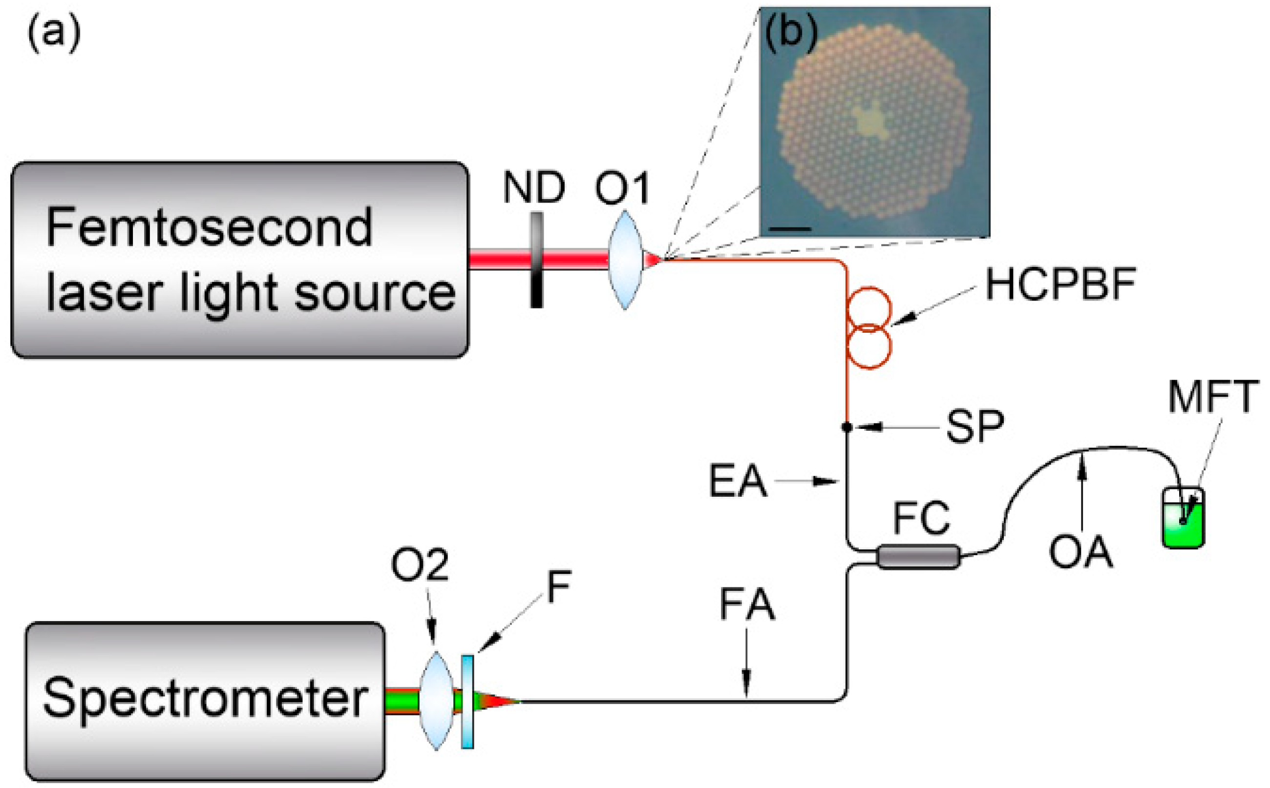
2. Materials and Methods

The main goal in the paper was to present a truly all-fiber-optic TPEF sensor setup, which requires a reliable connection between the HCPBF and MMF elements. The latter was provided by the fiber fusion splicing procedure, performed with a conventional arc fusion splicer (FSU 975, Ericsson, Stockholm, Sweden). The splicing procedure of HCPBF and MMF is a challenging task on its own, and is further discussed in Section 3.1.1 of this paper. The HCPBF (HC-800-02, NKT Photonics, Birkerød, Denmark) was spliced with one of the arms of a Y-type, multimode, 50:50 coupling ratio (CR, at 850 and 1300 nm) fiber optic coupler (Cellco, Kobylanka, Poland). It should be noted that the coupler’s CR was different at 780 nm, and to determine its performance at the spectral windows of interest, namely 770–790 nm (excitation window, Wex) and 500–650 nm (TPEF window, Wfluo), a white light source (AQ4305, Yokogawa, Tokyo, Japan) was coupled into the coupler’s common port, and the output spectra of the remaining ports were recorded with a USB spectrometer (USB-2000, OceanOptics, Largo, FL, USA). The obtained values of CR were ~80:20 for both Wex and Wfluo, and the arm with higher coupling efficiency was chosen to couple with the excitation signal, hence its given name—excitation arm (EA). The fusion splicer was also used to create a microlens at the tip of the fiber coupler’s common arm, which helped in increasing the efficiency of both the excitation and collection of the TPEF signal. To characterize the optical performance of the fabricated microlensed fiber tip (MFT), its output beam profile was measured with a beam profiler (BP109-IR, Thorlabs, Newton, NJ, USA).
The presence of a solid-core MMF coupler was expected to introduce significant temporal broadening of the coupled, fs-duration laser pulses. Thus, prior to the fluorescence excitation detection experiments, it was necessary to determine the sensor’s influence on the temporal profile of the transmitted ultrashort laser pulses via measurements of the autocorrelation function (ACF). The problem of dispersion in the MMF coupler was addressed in two ways: firstly, the lengths of the excitation and output arms of the coupler were each reduced from the initial ~1 m to about 30 cm; then, the HCPBF fiber was introduced into the setup, one of the characteristic features of which is positive value of the dispersion parameter D at 780 nm (DHCPBF780 ≈ 10 fs/(nm*m)), according to [90]), which can be expected to pre-compensate the chromatic dispersion of the MMF coupler. The ACF measurements were performed with an autocorrelator (pulseCheck, A.P.E. GmbH, Berlin, Germany), for four different cases—laser output pulse, HCPBF output pulse, fiber coupler with reduced arm lengths output pulse, and HCPBF+fiber coupler output pulse. Fiber output beams were collimated with a 10× microscope objective, and then pointed onto the autocorrelator’s aperture. Coupling between the HCPBF and MMF coupler’s excitation arm was performed with the fusion splicer, and the pulse widths of the pre-spliced (butt-coupled) and spliced fibers were also measured. This was of great importance, as splicing photonic crystal fibers always requires lower temperatures, making them much more prone to core displacement, which, in turn, can cause different mode excitation in the MMF and influence the final output pulse width.
The two-photon fluorescence spectroscopy setup, based on almost exclusively optical fiber components, is presented in Figure 1a.
A femtosecond laser light source (EFOA-SH, Atseva, Fort Collins, CO, USA), providing ultrashort light pulses of λlaser = 780 nm and τlaser = 130 fs, at frep = 78 MHz and Pavg = 120 mW, was coupled via a 10× microscope objective (NAMO = 0.26) into the HCPBF (NAHCPBF ≈ 0.2). The total length of the HCPBF was ~9 m, and the the maximum power at its output was 60 mW (half the input), mainly due to the attenuation characteristic of the fiber, as well as the mismatch between the NAMO and NAHCPBF. The coupling was performed in free space, with a use of the 3D translation stage (MBT616D, Thorlabs, Newton, NJ, USA). The laser output power was additionally controlled with a variable neutral density (ND) filter (ND-100C-4M, Thorlabs, Newton, NJ, USA). The MFT was immersed in a 10−2 M NaOH solution of fluorescein (Chempur, Piekary Śląskie, Poland) with concentration Cfluo = 10−5 M. The fluorescence signal was recollected by the MFT, and the remaining arm of the fiber coupler (fluorescence arm–FA, see Figure 1a) was used to transmit it (fluorescence signal) to the USB spectrometer. The FA’s output signal was additionally filtered (FGB37-A, Tholabs, Newton, NJ, USA) to reduce the amount of backscattered excitation light, and then focused onto the slit of the spectrometer with another 10× microscope objective. The spectrometer’s integration time (tint) during the fluorescence measurements was 2 s.

3. Results and Discussion

3.1. Combining the HCPBF and MM, Solid-Core Fiber with An Arc Fusion Splicer

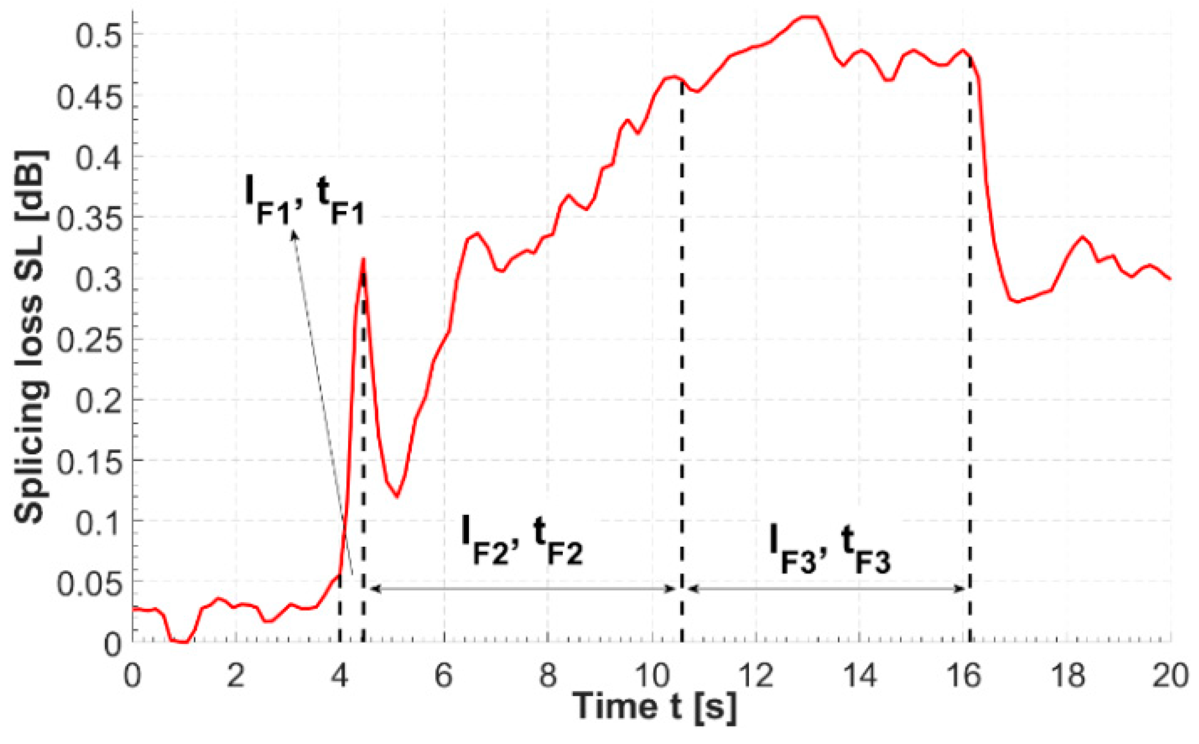
3.1.1. Arc Fusion Splicing of HCPBF and Solid-Core MMF

When splicing dissimilar fibers, the loss figure of such splicing is mainly governed by the fibers’ mode field mismatch, causing the splice to be non-symmetrical in terms of the transmission direction (i.e., the splice loss will be lower from the smaller MFD fiber to the larger MFD fiber than in the opposite direction). This loss can be reliably estimated by calculating the mode field overlap integral of the spliced fibers [91], however the complicated mode structure of the HCPBFs makes this method hard to implement [85]. Moreover, the mechanics of splicing MOFs is inherently different due to the presence of the photonic structure. The effect of its collapse during the splicing poses a major challenge, and many researchers have studied it extensively [79,84,86]. In general, the microstructured cladding collapses due to the silica’s viscosity being greatly reduced in the high-temperature region of fusion arc discharge. Additionally, the presence of air holes in HCPBFs (and MOFs) severely distracts and reduces the rate of heat transfer from the fiber’s outer surface to its core, causing a difference in its temperature and directly influencing both the optical losses and mechanical properties of the splice. This has resulted in a general preference for using sophisticated glass processing stations, such as filament fusion splicers or CO2 laser-based fiber splicers, which provide a very stable and uniform heat distribution across the splice area, making them an extremely reliable device for the purpose of splicing MOFs. However, the price of such systems greatly reduces their affordability, whereas arc fusion splicers, due to their common presence and ease of use, make for a very interesting alternative, even though they are not as effective due to the electrical arc’s susceptibility to the environment, wear of electrodes, etc. [81].
The initial splicing parameters used during this study were based on the previously mentioned work presented by Thapa et al. [85]. However, using the proposed parameters to splice the HCPBF and MMF used in our experiment resulted in extremely fragile splices, which broke almost immediately after removing the fibers from the splicers clamps. We attribute this behavior to the fact that the photonic structure diameter (dstruct) of our HCPBF is much smaller than in the case of HCPBF used by our predecessors [85] (45 and 70 μm, respectively), and in turn the total volume of glass is increased in our HCPBF. As a result, the latter requires higher temperatures (and higher splicing currents) to heat it properly and form a strong splice; this conclusion has been supported by the observations of Xiao et al. [86]. A detailed description of the splicing procedure, as well as the values of the fusion currents, times and offset, crucial for the quality of the splice, can be found in Appendix A. The measured values of splicing loss (SL) and bending radius (rbend) of five consecutive splices, fabricated with the proposed program, are presented in Table 1. Each splice withstood bending, with rbend ≈ 1.8 cm, while the average SL (transmission direction ‘HCPBF to MMF’) was 0.32 dB. Bending the fabricated splices with rbend = 1.8 cm had minimal influence on overall loss figure: splice bending loss (SBL) did not exceed the value of 0.07 dB. An example of a successful splice is presented in Figure 2a. The collapse of the photonic structure causes bright scattering and reflection of the transmitted signal at the HCPBF-MMF interface, observable on the splicers screen and with the naked eye (Figure 2b,c). Nevertheless, as mentioned previously, one can expect that when a small core fiber (HCPBF) is spliced with a large core fiber (MMF), the splice loss should be relatively small when signal transmission occurs in the ‘HCPBF to MMF’ direction.

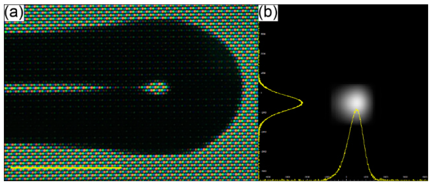
3.1.2. Microlensed Tip of MMF Coupler for the Enhancement of Two-Photon Excited Fluorescence

Fabrication and analysis of the optical performance of MFTs has previously been described by several researchers [75,77,78], while the fusion splicer program details and parameters used for this particular MFT are presented in Appendix A. The main goal was to obtain a small fiber end-face curvature, allowing the fiber output beam to be focused and the efficiency of TPEF to be enhanced. A picture of the fabricated MFT and its output beam profile are presented in Figure 3a,b, respectively. The beam profile was measured in the far field, showing the Gaussian-like intensity distribution in both the X and Y directions, and thus demonstrating good spatial beam quality. The working distance of the MFT (WDMFT), measured according to the method presented in [78], was ~180 μm.

3.2. ACF Traces of the Proposed HCPBF-MMF Coupler Setup and Its Application for the Purpose of Multiphoton Fluorescence Spectroscopy

Dispersion effects introduced by the solid-core fibers can have a destructive influence on the fundamental laser pulse width, and in turn impair the efficiency of nonlinear optical effects such as MPEF. The obtained ACF traces of the fiber-coupled fs laser beam are presented in Figure 4. Each of the ACFs was fitted with a Lorentzian-shaped curve, as it exhibited the lowest approximation errors (R2 values for each fit were as good as 0.998). As mentioned before, HCPBF’s dispersion parameter D at 780 nm is DHCPBF780 ≈ 10 fs/(nm*m), suggesting that the total pulse broadening within ~9 m length of this fiber is about 90 fs. Figure 4a shows the ACF trace of HCPBF coupled pulse, whose calculated width (τHCPBF) was 190 fs.
Comparing this with the τ of the laser beam, coupled into the MMF coupler (τMMF = 336 fs), one can observe that τMMF is nearly twice the τHCPBF. Combining these two types of fibers (Figure 4c,d), the effect of dispersion compensation can be observed, resulting in the reduction of the τMMF by about 86 fs (τHCPBF+MMF ≈ 250 fs), which corresponds to the total value of DHCPBF780 after 9 m length of fiber, proving the anomalous dispersion of the HCPBF at λ = 780 nm. Additionally, due to the splicing procedure, which softened the fibers and could potentially result in the displacement of their cores, we measured the width of the spliced HCPBF and MMF coupler output pulse (Figure 4d). The value of τFWHM in this case was 255 fs, showing that, although there is a slight difference between the butt-coupled and spliced setups, this was not large enough to consider splicing as a procedure that significantly influences the pulse width. The experimental error in these measurements, apart from the resolution of the autocorrelator (Δτ = ±2 fs), is connected mainly with the problem of exciting different modes during the coupling of HCPBF and MMF. We did not study this effect, however it was not necessary due to the mechanical requirements of the splice. Mechanically strong splices should be geometrically symmetrical, which means that the MMF excitation conditions should be constant, since the core of MMF and HCPBF should run along the same optical axis after coupling prior to the splicing. In this case, the main source of the error should be the eccentricity of the cores of the spliced fibers; however, it does not influence the final pulse width significantly, which was proven by the pulse widths obtained for pre-spliced and spliced fibers. It should also be mentioned that the total pulse broadening was also increased by the two 10× objectives present in the setup; however, since it should be on the order of few fs, we considered it to be negligible.
To prove that the proposed HCPBF-MMF coupler hybrid can be considered a candidate for the purpose of MPEF spectroscopy, the TPEF emission spectra of fluorescein were measured, as depicted in Figure 5. The average power delivered to the sample was 20 mW. Two emission peaks can be observed, one in the ~760–800 nm range, originating from the excitation laser, and another one, spanning ~480 to 580 nm, with a maximum at 518 nm, which is connected with examined fluorescein solution. The obtained results are in good agreement with those presented in [92]. Although the collected spectrum is contaminated with the backscattered laser radiation (both by the sample and due to the weak isolation of the MMF coupler), the presented idea can be considered a promising step towards simple, fiber-based optical biopsy devices.

4. Conclusions

This work presented a hybrid between an HCF and an MMF Y-type coupler, and its application to multiphoton fluorescence spectroscopy. Arc fusion splicing of HCF and MMF was presented, resulting in low splicing and bending loss (0.32 and 0.04 dB (at bending radius ≥ 1.8 cm), respectively) splices, which shows the opportunity of combining these two distinct types of fibers in a simple and affordable fashion. The presented fiber coupler hybrid was used in a proof-of-concept multiphoton spectroscopy experiment, with the coupler’s common arm acting as a fluorescence excitation-detection arm. The tip of this arm was curved with the use of the same arc fusion splicer, creating a microlens with a working distance of ~180 μm and Gaussian-like output beam profile. This tip ensured focusing of the output beam, which is an important factor for the efficiency of exciting fluorescence due to the multiphoton absorption. Fluorescence was excited in a 10−2 NaOH fluorescein solution (Cfluo 10−5 M). The recollected fluorescence signal was recorded with a USB spectrometer. The presented fiber-optic setup has three features which are very interesting from the sensing point of view, namely size, price and simplicity. It should be noted that the MMF coupler used in this research is not an optimal solution for the spectral region of interest (400–800 nm), and thus one can suppose that the efficiency of the proposed setup could be increased by replacing the coupler with a one designed for the VIS spectral region. Nevertheless, the proposed HCPBF and MMF coupler combination allowed for the delivery of 130-fs short laser pulses with moderate dispersive broadening (255 fs at the HCPBF+MMF coupler output), making it a solution considerable for applications in the field of non-linear optics.

Author Contributions

H.I.S. and M.A.P. designed the experiment, conducted the measurements, discussed the results and prepared the data. All the authors edited the manuscript. E.B.-P. supervised the research.

Funding

This research was funded by the Wroclaw University of Science and Technology Grants No. 0401/0140/17 and 0402/0149/17.

Acknowledgments

We would like to thank prof. Sławomir Sujecki for his support during this research.

Conflicts of Interest

The authors declare no conflict of interest.

Appendix A. Arc Fusion Splicing Procedures–Technical Notes

Appendix A.1. Arc Fusion Splicing of HCPBF and MMF

The optimum splicing parameters were found by performing over 30 splices, and the splice pass/fail criteria were as follows: splice loss (SL) ≤ 0.5 dB and splice bending radius (rbend) ≤ 1.8 cm. It could be possible to improve these parameters, however they satisfied the needs of our experiment, as only a single splice was required. Prior to splicing, about 2 cm of both HCPBF and MMF were stripped, cleaved (FC-6S, Sumitomo Electric, Raleigh, NC, USA) and cleaned with dry, lint-free tissue, resulting in good quality, clean fiber facets. Specific splicing parameters are presented in Table A1. As the splice itself is formed during splicing phases 2 and 3 (i.e., when the fusion currents 2 and 3 are applied), the changes were implemented mainly for these parameters. By connecting the MMF output to the optical power meter (S121C with PM100D, Thorlabs, Newton, NJ, USA) the evolution of the output power (Pout_MM) was observed (Figure A1) and it was noted that during splice phase 1, when a 10 mA current was applied for 0.2 s, Pout_MM fell quickly, which was a hint that the optimum current value lays between the 6.3 and 10 mA.
Table A1. Arc fusion splicer parameters adjusted for splicing hollow-core photonic crystal fiber (HC-800-02, NKT Photonics, Birkerød, Denmark) and solid-core, multimode, type OM2 fibers.
Splicing Parameter NameParameter Values
Prefuse time (s)0.1
Prefuse current (mA)10
Gap (μm)10
Overlap (μm)10
Fusion time 1 tF1 (s)0.2
Fusion current 1 IF1 (mA)10
Fusion time 2 tF2 (s)6
Fusion current 2 IF2 (mA)9.4
Fusion time 3 tF3 (s)6
Fusion current 3 IF3 (mA)8
Offset (-)260
Figure A1. Evolution of splicing loss over time measured during the HCPBF-MMF splicing procedure. Dotted lines indicate moments of start and stop of three main splicing phases. SL rise is most intense during phase 1 of splicing (i.e., when the fiber tips are softened and prepared for forming a splice with a high fusion current). The SL value falls almost immediately after the splicing has stopped; the splicers program stops pushing the fibers towards each other, which probably reduces the displacement between the cores of both fibers and in turn positively influences coupling between them in the splice region.
Fibers 06 00077 g0a1

Appendix A.2. Fabrication of the Fiber Microlens at the Tip of the MMF Coupler

MFT fabrication details are presented in Table A2. The same arc fusion splicer as in the case of splicing HCPBF and MMF was used. Moving the MMF tip from the center of the arc curvature by 50 μm (offset = 305) allowed for better control of the lens formation process.
Table A2. Arc fusion splicer parameters for the fabrication of microlensed fiber tip. The program was based on the splicers tapering procedure, which means that the fiber tip was constantly being pulled away from the splicers arc. A large offset (approximately 50 μm from the center arc) ensured that the lens curvature was small enough (about 150 μm), while large values of the arc currents made the process quicker than in the case of standard fiber tapering.
Parameter NameValue
Prefuse time (s)0.2
Prefuse current (mA)10
Fusion time 1 tFL1 (s)2
Fusion current 1 IFL1 (mA)15
Fusion time 2 tF2 (s)2
Fusion current 2 IF2 (mA)10
Fusion time 3 tF3 (s)1
Fusion current 3 IF3 (mA)10
Offset (-)305

References

  1. Cregan, R.F.; Mangan, B.J.; Knight, J.C.; Birks, T.A.; Russell, P.S.J.; Roberts, P.J.; Allan, D.C. Single-mode photonic band gap guidance of light in air. Science 1999, 285, 1537–1539. [Google Scholar] [CrossRef] [PubMed]
  2. Chen, M.-Q.; Zhao, Y.; Xia, F.; Peng, Y.; Tong, R.-J. High sensitivity temperature sensor based on fiber air-microbubble fabry-perot interferometer with pdms-filled hollow-core fiber. Sens. Actuators A Phys. 2018, 275, 60–66. [Google Scholar] [CrossRef]
  3. Sun, H.; Luo, H.; Wu, X.; Liang, L.; Wang, Y.; Ma, X.; Zhang, J.; Hu, M.; Qiao, X. Spectrum ameliorative optical fiber temperature sensor based on hollow-core fiber and inner zinc oxide film. Sens. Actuators B Chem. 2017, 245, 423–427. [Google Scholar] [CrossRef]
  4. Zhang, Z.; Liao, C.; Tang, J.; Wang, Y.; Bai, Z.; Li, Z.; Guo, K.; Deng, M.; Cao, S.; Wang, Y. Hollow-core-fiber-based interferometer for high-temperature measurements. IEEE Photonics J. 2017, 9, 1–9. [Google Scholar] [CrossRef]
  5. Wei, C.; Young, J.T.; Menyuk, C.R.; Hu, J. Temperature sensor using fluid-filled negative curvature fibers. In Proceedings of the Conference on Lasers and Electro-Optics, San Jose, CA, USA, 13–18 May 2018. [Google Scholar]
  6. Sardar, M.R.; Faisal, M. Gas sensor based on octagonal hollow core photonic crystal fiber. In Proceedings of the 2017 IEEE International Conference on Imaging, Vision & Pattern Recognition (icIVPR), Dhaka, Bangladesh, 13–14 February 2017. [Google Scholar]
  7. Yang, F.; Jin, W.; Lin, Y.; Wang, C.; Lut, H.; Tan, Y. Hollow-core microstructured optical fiber gas sensors. J. Lightwave Technol. 2017, 35, 3413–3424. [Google Scholar] [CrossRef]
  8. Lin, Y.; Liu, F.; He, X.; Jin, W.; Zhang, M.; Yang, F.; Ho, H.L.; Tan, Y.; Gu, L. Distributed gas sensing with optical fibre photothermal interferometry. Opt. Express 2017, 25, 31568–31585. [Google Scholar] [CrossRef] [PubMed]
  9. Nikodem, M.; Krzempek, K.; Dudzik, G.; Abramski, K. Hollow core fiber-assisted absorption spectroscopy of methane at 3.4 μm. Opt. Express 2018, 26, 21843–21848. [Google Scholar] [CrossRef] [PubMed]
  10. Shi, Q.; Lv, F.; Wang, Z.; Jin, L.; Hu, J.J.; Liu, Z.; Kai, G.; Dong, X. Environmentally stable fabry–p rot-type strain sensor based on hollow-core photonic bandgap fiber. IEEE Photonics Technol. Lett. 2008, 20, 237–239. [Google Scholar] [CrossRef]
  11. Zhao, Y.; Lv, R.-Q.; Ying, Y.; Wang, Q. Hollow-core photonic crystal fiber fabry–perot sensor for magnetic field measurement based on magnetic fluid. J. Light. Technol. 2012, 44, 899–902. [Google Scholar] [CrossRef]
  12. Jin, L.; Guan, B.-O.; Wei, H. Sensitivity characteristics of fabry-perot pressure sensors based on hollow-core microstructured fibers. J. Light. Technol. 2013, 31, 2526–2532. [Google Scholar]
  13. Bykov, D.S.; Schmidt, O.A.; Euser, T.G.; Russell, P.S.J. Flying particle sensors in hollow-core photonic crystal fibre. Nat. Photonics 2015, 9, 461. [Google Scholar] [CrossRef]
  14. Zeltner, R.; Bykov, D.S.; Xie, S.; Euser, T.G.; Russell, P.S.J. Fluorescence-based flying-particle sensor in liquid-filled hollow-core photonic crystal fiber. In Proceedings of the 2016 Conference on Lasers and Electro-Optics (CLEO), San Jose, CA, USA, 5–10 June 2016. [Google Scholar]
  15. Momota, M.R.; Hasan, M.R. Hollow-core silver coated photonic crystal fiber plasmonic sensor. Opt. Mater. 2018, 76, 287–294. [Google Scholar] [CrossRef]
  16. Zeisberger, M.; Schmidt, M.A. Analytic model for the complex effective index of the leaky modes of tube-type anti-resonant hollow core fibers. Sci. Rep. 2017, 7, 11761. [Google Scholar] [CrossRef] [PubMed]
  17. Johnson, S.G.; Ibanescu, M.; Skorobogatiy, M.; Weisberg, O.; Engeness, T.D.; Soljačić, M.; Jacobs, S.A.; Joannopoulos, J.D.; Fink, Y. Low-loss asymptotically single-mode propagation in large-core omniguide fibers. Opt. Express 2001, 9, 748–779. [Google Scholar] [CrossRef] [PubMed]
  18. Fink, Y.; Winn, J.N.; Fan, S.; Chen, C.; Michel, J.; Joannopoulos, J.D.; Thomas, E.L. A dielectric omnidirectional reflector. Science 1998, 282, 1679. [Google Scholar] [CrossRef] [PubMed]
  19. Engeness, T.D.; Ibanescu, M.; Johnson, S.G.; Weisberg, O.; Skorobogatiy, M.; Jacobs, S.; Fink, Y. Dispersion tailoring and compensation by modal interactions in omniguide fibers. Opt. Express 2003, 11, 1175–1196. [Google Scholar] [CrossRef] [PubMed]
  20. Zeisberger, M.; Tuniz, A.; Schmidt, M.A. Analytic model for the complex effective index dispersion of metamaterial-cladding large-area hollow core fibers. Opt. Express 2016, 24, 20515–20528. [Google Scholar] [CrossRef] [PubMed]
  21. Poletti, F.; Petrovich Marco, N.; Richardson David, J. Hollow-core photonic bandgap fibers: Technology and applications. Nanophotonics 2013, 2, 315. [Google Scholar] [CrossRef]
  22. Fokoua, E.N.; Richardson, D.J.; Poletti, F. Impact of structural distortions on the performance of hollow-core photonic bandgap fibers. Opt. Express 2014, 22, 2735–2744. [Google Scholar] [CrossRef] [PubMed] [Green Version]
  23. Bufetov, I.; Kosolapov, A.; Pryamikov, A.; Gladyshev, A.; Kolyadin, A.; Krylov, A.; Yatsenko, Y.; Biriukov, A. Revolver hollow core optical fibers. Fibers 2018, 6, 39. [Google Scholar] [CrossRef]
  24. Wang, Y.; Couny, F.; Roberts, P.J.; Benabid, F. Low loss broadband transmission in optimized core-shape kagome hollow-core PCF. In Proceedings of the CLEO/QELS: 2010 Laser Science to Photonic Applications, San Jose, CA, USA, 16–21 May 2010. [Google Scholar]
  25. Stawska, H.; Popenda, M.; Bereś-Pawlik, E. Anti-resonant hollow core fibers with modified shape of the core for the better optical performance in the visible spectral region—A numerical study. Polymers 2018, 10, 899. [Google Scholar] [CrossRef]
  26. Kosolapov, A.F.; Alagashev, G.K.; Kolyadin, A.N.; Pryamikov, A.D.; Biryukov, A.S.; Bufetov, I.A.; Dianov, E.M. Hollow-core revolver fibre with a double-capillary reflective cladding. Quantum Electron. 2016, 46, 267. [Google Scholar] [CrossRef]
  27. Chen, Y.; Saleh, M.F.; Joly, N.Y.; Biancalana, F. Low-loss single-mode negatively curved square-core hollow fibers. Opt. Lett. 2017, 42, 1285–1288. [Google Scholar] [CrossRef] [PubMed]
  28. Habib, M.S.; Bang, O.; Bache, M. Low-loss single-mode hollow-core fiber with anisotropic anti-resonant elements. Opt. Express 2016, 24, 8429–8436. [Google Scholar] [CrossRef] [PubMed]
  29. Nawazuddin, M.B.S.; Wheeler, N.V.; Hayes, J.R.; Bradley, T.; Sandoghchi, S.R.; Gouveia, M.A.; Jasion, G.T.; Richardson, D.J.; Poletti, F. Lotus shaped negative curvature hollow core fibre with 10.5 db/km at 1550 nm wavelength. In Proceedings of the 2017 European Conference on Optical Communication (ECOC), Gothenburg, Sweden, 17–21 September 2017; pp. 1–3. [Google Scholar]
  30. Roberts, P.J.; Couny, F.; Sabert, H.; Mangan, B.J.; Williams, D.P.; Farr, L.; Mason, M.W.; Tomlinson, A.; Birks, T.A.; Knight, J.C.; et al. Ultimate low loss of hollow-core photonic crystal fibres. Opt. Express 2005, 13, 236–244. [Google Scholar] [CrossRef] [PubMed]
  31. Roberts, P.J.; Williams, D.P.; Sabert, H.; Mangan, B.J.; Bird, D.M.; Birks, T.A.; Knight, J.C.; Russell, P.S.J. Design of low-loss and highly birefringent hollow-core photonic crystal fiber. Opt. Express 2006, 14, 7329–7341. [Google Scholar] [CrossRef] [PubMed] [Green Version]
  32. Amezcua-Correa, R.; Broderick, N.G.R.; Petrovich, M.N.; Poletti, F.; Richardson, D.J. Design of 7 and 19 cells core air-guiding photonic crystal fibers for low-loss, wide bandwidth and dispersion controlled operation. Opt. Express 2007, 15, 17577–17586. [Google Scholar] [CrossRef] [PubMed]
  33. Jung, Y.; Sleiffer, V.A.J.M.; Baddela, N.; Petrovich, M.N.; Hayes, J.R.; Wheeler, N.V.; Gray, D.R.; Fokoua, E.N.; Wooler, J.P.; Wong, N.H.L.; et al. First demonstration of a broadband 37-cell hollow core photonic bandgap fiber and its application to high capacity mode division multiplexing. In Proceedings of the 2013 Optical Fiber Communication Conference and Exposition and the National Fiber Optic Engineers Conference (OFC/NFOEC), Anaheim, CA, USA, 17–21 March 2013. [Google Scholar]
  34. Belardi, W.; Knight, J.C. Effect of core boundary curvature on the confinement losses of hollow antiresonant fibers. Opt. Express 2013, 21, 21912–21917. [Google Scholar] [CrossRef] [PubMed]
  35. Belardi, W. Design and properties of hollow antiresonant fibers for the visible and near infrared spectral range. J. Light. Technol. 2015, 33, 4497–4503. [Google Scholar] [CrossRef]
  36. Vaiano, P.; Carotenuto, B.; Pisco, M.; Ricciardi, A.; Quero, G.; Consales, M.; Crescitelli, A.; Esposito, E.; Cusano, A. Lab on fiber technology for biological sensing applications. Laser Photonics Rev. 2016, 10, 922–961. [Google Scholar] [CrossRef]
  37. Ricciardi, A.; Crescitelli, A.; Vaiano, P.; Quero, G.; Consales, M.; Pisco, M.; Esposito, E.; Cusano, A. Lab-on-fiber technology: A new vision for chemical and biological sensing. Analyst 2015, 140, 8068–8079. [Google Scholar] [CrossRef] [PubMed]
  38. Liu, X.-L.; Ding, W.; Wang, Y.-Y.; Gao, S.-F.; Cao, L.; Feng, X.; Wang, P. Characterization of a liquid-filled nodeless anti-resonant fiber for biochemical sensing. Opt. Lett. 2017, 42, 863–866. [Google Scholar] [CrossRef] [PubMed]
  39. Liu, X.-L.; Wang, Y.-Y.; Ding, W.; Gao, S.-F.; Cao, L.; Feng, X.; Wang, P. Liquid-core nodeless anti-resonant fiber for biochemical sensing. In Proceedings of the Conference on Lasers and Electro-Optics, San Jose, CA, USA, 14–19 May 2017. [Google Scholar]
  40. Nissen, M.; Doherty, B.; Hamperl, J.; Kobelke, J.; Weber, K.; Henkel, T.; Schmidt, A.M. Uv absorption spectroscopy in water-filled antiresonant hollow core fibers for pharmaceutical detection. Sensors 2018, 18, 478. [Google Scholar] [CrossRef] [PubMed]
  41. Iwata, T.; Katagiri, T.; Matsuura, Y. Real-time analysis of isoprene in breath by using ultraviolet-absorption spectroscopy with a hollow optical fiber gas cell. Sensors 2016, 16, 2058. [Google Scholar] [CrossRef] [PubMed]
  42. Yan, H.; Gu, C.; Yang, C.; Liu, J.; Jin, G.; Zhang, J.; Hou, L.; Yao, Y. Hollow core photonic crystal fiber surface-enhanced raman probe. Appl. Physics Lett. 2006, 89, 204101. [Google Scholar] [CrossRef]
  43. Wang, C.; Zeng, L.; Li, Z.; Li, D. Review of optical fibre probes for enhanced raman sensing. J. Raman Spectrosc. 2017, 48, 1040–1055. [Google Scholar] [CrossRef]
  44. Khetani, A.; Riordon, J.; Tiwari, V.; Momenpour, A.; Godin, M.; Anis, H. Hollow core photonic crystal fiber as a reusable raman biosensor. Opt. Express 2013, 21, 12340–12350. [Google Scholar] [CrossRef] [PubMed]
  45. Stoddart, P.R.; White, D.J. Optical fibre sers sensors. Anal. Bioanal. Chem. 2009, 394, 1761–1774. [Google Scholar] [CrossRef] [PubMed]
  46. Geng, Y.; Xu, Y.; Tan, X.; Wang, L.; Li, X.; Du, Y.; Hong, X. A simplified hollow-core photonic crystal fiber sers probe with a fully filled photoreduction silver nanoprism. Sensors 2018, 18, 1726. [Google Scholar] [CrossRef] [PubMed]
  47. Yang, X.; Shi, C.; Wheeler, D.; Newhouse, R.; Chen, B.; Zhang, J.Z.; Gu, C. High-sensitivity molecular sensing using hollow-core photonic crystal fiber and surface-enhanced raman scattering. J. Opt. Soc. Am. A 2010, 27, 977–984. [Google Scholar] [CrossRef] [PubMed]
  48. Albrecht, M.G.; Creighton, J.A. Anomalously intense raman spectra of pyridine at a silver electrode. J. Am. Chem. Soc. 1977, 99, 5215–5217. [Google Scholar] [CrossRef]
  49. Laing, S.; Gracie, K.; Faulds, K. Multiplex in vitro detection using sers. Chem. Soc. Rev. 2016, 45, 1901–1918. [Google Scholar] [CrossRef] [PubMed] [Green Version]
  50. Khetani, A.; Momenpour, A.; Alarcon, E.I.; Anis, H. Hollow core photonic crystal fiber for monitoring leukemia cells using surface enhanced raman scattering (sers). Biomed. Opt. Express 2015, 6, 4599–4609. [Google Scholar] [CrossRef] [PubMed]
  51. Dinish, U.S.; Balasundaram, G.; Chang, Y.T.; Olivo, M. Sensitive multiplex detection of serological liver cancer biomarkers using sers-active photonic crystal fiber probe. J. Biophotonics 2013, 7, 956–965. [Google Scholar] [CrossRef] [PubMed]
  52. Chow, K.K.; Short, M.; Lam, S.; McWilliams, A.; Zeng, H. A raman cell based on hollow core photonic crystal fiber for human breath analysis. Med. Phys. 2016, 41, 092701. [Google Scholar] [CrossRef] [PubMed]
  53. Khetani, A.; Tiwari, V.S.; Harb, A.; Anis, H. Monitoring of heparin concentration in serum by raman spectroscopy within hollow core photonic crystal fiber. Opt. Express 2011, 19, 15244–15254. [Google Scholar] [CrossRef] [PubMed]
  54. Brustlein, S.; Berto, P.; Hostein, R.; Ferrand, P.; Billaudeau, C.; Marguet, D.; Muir, A.; Knight, J.; Rigneault, H. Double-clad hollow core photonic crystal fiber for coherent raman endoscope. Opt. Express 2011, 19, 12562–12568. [Google Scholar] [CrossRef] [PubMed]
  55. Lombardini, A.; Mytskaniuk, V.; Sivankutty, S.; Andresen, E.R.; Chen, X.; Wenger, J.; Fabert, M.; Joly, N.; Louradour, F.; Kudlinski, A.; et al. High-resolution multimodal flexible coherent raman endoscope. Light Sci. Appl. 2018, 7, 10. [Google Scholar] [CrossRef]
  56. Yerolatsitis, S.; Yu, F.; McAughtrie, S.; Tanner, M.G.; Fleming, H.; Stone, J.M.; Campbell, C.J.; Birks, T.A.; Knight, J.C. Ultra-low background raman sensing using a negative-curvature fibre. In Proceedings of the OSA Advanced Photonics Congress 2018 (BGPP, IPR, NP, NOMA, Sensors, Networks, SPPCom, SOF), Zurich, Switzerland, 2–5 July 2018. [Google Scholar]
  57. Konorov, S.O.; Addison, C.J.; Schulze, H.G.; Turner, R.F.B.; Blades, M.W. Hollow-core photonic crystal fiber-optic probes for raman spectroscopy. Opt. Lett. 2006, 31, 1911–1913. [Google Scholar] [CrossRef] [PubMed]
  58. Couny, F.; Benabid, F.; Light, P.S. Large-pitch kagome-structured hollow-core photonic crystal fiber. Opt. Lett. 2006, 31, 3574–3576. [Google Scholar] [CrossRef] [PubMed]
  59. Ghenuche, P.; Rammler, S.; Joly, N.Y.; Scharrer, M.; Frosz, M.; Wenger, J.; Russell, P.S.J.; Rigneault, H. Kagome hollow-core photonic crystal fiber probe for raman spectroscopy. Opt. Lett. 2012, 37, 4371–4373. [Google Scholar] [CrossRef] [PubMed]
  60. Tai, S.-P.; Chan, M.-C.; Tsai, T.-H.; Guol, S.-H.; Chen, L.-J.; Sun, C.-K. Two-photon fluorescence microscope with a hollow-core photonic crystal fiber. Opt. Express 2004, 12, 6122–6128. [Google Scholar] [CrossRef] [PubMed]
  61. Yu, J.; Zeng, H.; Lui, H.; Skibina, J.S.; Steinmeyer, G.; Tang, S. Characterization and application of chirped photonic crystal fiber in multiphoton imaging. Opt. Express 2014, 22, 10366–10379. [Google Scholar] [CrossRef] [PubMed]
  62. Sherlock, B.; Fei, Y.; Jim, S.; Sean, W.; Carl, P.; Neil Mark, A.A.; French Paul, M.W.; Jonathan, K.; Chris, D. Tunable fibre-coupled multiphoton microscopy with a negative curvature fibre. J. Biophotonics 2016, 9, 715–720. [Google Scholar] [CrossRef] [PubMed] [Green Version]
  63. Popenda, M.A.; Stawska, H.I.; Mazur, L.M.; Jakubowski, K.; Kosolapov, A.; Kolyadin, A.; Bereś-Pawlik, E. Application of negative curvature hollow-core fiber in an optical fiber sensor setup for multiphoton spectroscopy. Sensors 2017, 17, 2278. [Google Scholar] [CrossRef] [PubMed]
  64. Kobayashi, T.; Katagiri, T.; Matsuura, Y. Multi-element hollow-core anti-resonant fiber for infrared thermal imaging. Opt. Express 2016, 24, 26565–26574. [Google Scholar] [CrossRef] [PubMed]
  65. Arora, N.; Martins, D.; Ruggerio, D.; Tousimis, E.; Swistel, A.J.; Osborne, M.P.; Simmons, R.M. Effectiveness of a noninvasive digital infrared thermal imaging system in the detection of breast cancer. Am. J. Surg. 2008, 196, 523–526. [Google Scholar] [CrossRef] [PubMed]
  66. Lahiri, B.B.; Bagavathiappan, S.; Jayakumar, T.; Philip, J. Medical applications of infrared thermography: A review. Infrared Phys. Technol. 2012, 55, 221–235. [Google Scholar] [CrossRef]
  67. Wang, Y.; Jin, W.; Ju, J.; Xuan, H.; Ho, H.L.; Xiao, L.; Wang, D. Long period gratings in air-core photonic bandgap fibers. Opt. Express 2008, 16, 2784–2790. [Google Scholar] [CrossRef] [PubMed] [Green Version]
  68. Yuan, T.; Zhong, X.; Guan, C.; Fu, J.; Yang, J.; Shi, J.; Yuan, L. Long period fiber grating in two-core hollow eccentric fiber. Opt. Express 2015, 23, 33378–33385. [Google Scholar] [CrossRef] [PubMed]
  69. Wu, Z.; Wang, Z.; Liu, Y.-G.; Han, T.; Li, S.; Wei, H. Mechanism and characteristics of long period fiber gratings in simplified hollow-core photonic crystal fibers. Opt. Express 2011, 19, 17344–17349. [Google Scholar] [CrossRef] [PubMed]
  70. Iadicicco, A.; Campopiano, S.; Cusano, A. Long-period gratings in hollow core fibers by pressure-assisted arc discharge technique. IEEE Photonics Technol. Lett. 2011, 23, 1567–1569. [Google Scholar] [CrossRef]
  71. Terrel, M.; Digonnet, M.J.F.; Fan, S. Polarization controller for hollow-core fiber. Opt. Lett. 2007, 32, 1524–1526. [Google Scholar] [CrossRef] [PubMed]
  72. Pang, M.; Jin, W. A hollow-core photonic bandgap fiber polarization controller. Opt. Lett. 2011, 36, 16–18. [Google Scholar] [CrossRef] [PubMed]
  73. Xuan, H.F.; Jin, W.; Ju, J.; Wang, Y.P.; Zhang, M.; Liao, Y.B.; Chen, M.H. Hollow-core photonic bandgap fiber polarizer. Opt. Lett. 2008, 33, 845–847. [Google Scholar] [CrossRef] [PubMed]
  74. Qian, W.; Zhao, C.-L.; Kang, J.; Dong, X.; Zhang, Z.; Jin, S. A proposal of a novel polarizer based on a partial liquid-filled hollow-core photonic bandgap fiber. Opt. Commun. 2011, 284, 4800–4804. [Google Scholar] [CrossRef]
  75. Kong, G.-J.; Kim, J.; Choi, H.-Y.; Im, J.E.; Park, B.-H.; Paek, U.-C.; Lee, B.H. Lensed photonic crystal fiber obtained by use of an arc discharge. Opt. Lett. 2006, 31, 894–896. [Google Scholar] [CrossRef] [PubMed]
  76. Ryu, S.Y.; Choi, H.Y.; Na, J.; Choi, W.J.; Lee, B.H. Lensed fiber probes designed as an alternative to bulk probes in optical coherence tomography. Appl. Opt. 2008, 47, 1510–1516. [Google Scholar] [CrossRef] [PubMed]
  77. Choi, H.Y.; Ryu, S.Y.; Na, J.; Lee, B.H.; Sohn, I.-B.; Noh, Y.-C.; Lee, J. Single-body lensed photonic crystal fibers as side-viewing probes for optical imaging systems. Opt. Lett. 2008, 33, 34–36. [Google Scholar] [CrossRef] [PubMed]
  78. Stawska, H.; Popenda, M.; Langer, Ł.; Bereś-Pawlik, E. Application of the hollow core fiber ended with fiber microlens in the multiphoton excitation setup. In Proceedings of the 20th International Conference on Transparent Optical Networks (ICTON 2018), Bucharest, Romania, 1–5 July 2018. [Google Scholar]
  79. Xiao, L.; Jin, W.; Demokan, M.S.; Ho, H.L.; Hoo, Y.L.; Zhao, C. Fabrication of selective injection microstructured optical fibers with a conventional fusion splicer. Opt. Express 2005, 13, 9014–9022. [Google Scholar] [CrossRef] [PubMed]
  80. Tachikura, M. Fusion mass-splicing for optical fibers using electric discharges between two pairs of electrodes. Appl. Opt. 1984, 23, 492–498. [Google Scholar] [CrossRef] [PubMed]
  81. Yablon, A.D. Mechanics of fusion splicing. In Optical Fiber Fusion Splicing; Springer Series in Optical Sciences; Springer: Berlin/Heidelberg, Germany, 2005; pp. 49–89. [Google Scholar]
  82. Bennett, P.J.; Monro, T.M.; Richardson, D.J. Toward practical holey fiber technology:?Fabrication, splicing, modeling, and characterization. Opt. Lett. 1999, 24, 1203–1205. [Google Scholar] [CrossRef] [PubMed]
  83. Bourliaguet, B.; Paré, C.; Émond, F.; Croteau, A.; Proulx, A.; Vallée, R. Microstructured fiber splicing. Opt. Express 2003, 11, 3412–3417. [Google Scholar] [PubMed]
  84. Yablon, A.D. Fusion splicing of specialty fiber. In Optical Fiber Fusion Splicing; Springer Series in Optical Sciences; Springer: Berlin/Heidelberg, Germany, 2005; pp. 229–253. [Google Scholar]
  85. Thapa, R.; Knabe, K.; Corwin, K.L.; Washburn, B.R. Arc fusion splicing of hollow-core photonic bandgap fibers for gas-filled fiber cells. Opt. Express 2006, 14, 9576–9583. [Google Scholar] [CrossRef] [PubMed]
  86. Xiao, L.; Demokan, M.S.; Jin, W.; Wang, Y.; Zhao, C. Fusion splicing photonic crystal fibers and conventional single-mode fibers: Microhole collapse effect. J. Light. Technol. 2007, 25, 3563–3574. [Google Scholar] [CrossRef] [Green Version]
  87. Wu, C.; Song, J.; Zhang, Z.; Song, N. High strength fusion splicing of hollow-core photonic bandgap fiber and single-mode fiber. In Proceedings of the Photonics and Fiber Technology 2016 (ACOFT, BGPP, NP), Sydney, Australia, 5–8 September 2016. [Google Scholar]
  88. Ma, H.; Chen, Z.; Jin, Z. Single-polarization coupler based on air-core photonic bandgap fibers and implications for resonant fiber optic gyro. J. Light. Technol. 2014, 32, 46–54. [Google Scholar] [CrossRef]
  89. Huang, X.; Ma, J.; Tang, D.; Yoo, S. Hollow-core air-gap anti-resonant fiber couplers. Opt. Express 2017, 25, 29296–29306. [Google Scholar] [CrossRef]
  90. Product spec. Sheet, hc-800-02 Photonic Crystal Fiber (nkt Photonics, Birkerød, Denmark). Available online: https://www.nktphotonics.com/wp-content/uploads/sites/3/2015/01/hc-800-1.pdf?1539002002 (accessed on 3 October 2018).
  91. Yablon, A.D. Optics of fusion splicing. In Optical Fiber Fusion Splicing; Springer Series in Optical Sciences; Springer: Berlin/Heidelberg, Germany, 2005; pp. 91–135. [Google Scholar]
  92. Xu, C.; Webb, W.W. Measurement of two-photon excitation cross sections of molecular fluorophores with data from 690 to 1050 nm. J. Opt. Soc. Am. B 1996, 13, 481–491. [Google Scholar] [CrossRef]
Figure 1. (a) Multiphoton fluorescence measurement setup schematic. ND: variable neutral density filter; O1, O2: 10X/0.24 microscope objectives; HCPBF: hollow-core photonic bandgap fiber; SP: splice point; FC: multimode fiber coupler; EA, OA, FA: fiber coupler’s excitation, output and fluorescence arms, respectively; MFT: microlensed fiber tip; F: colored glass filter. The MFT output power is controlled with the ND, while the HCPBF allows the laser output pulse to be pre-compensated, reducing its temporal broadening due to the presence of FC. The FC had its EA and OA shortened to ~30 cm each. During the measurement, the MFT was immersed in a glass cuvette with a fluorescein solution, and multiphoton excited fluorescence was recollected and transmitted through the FA to the USB spectrometer. (b) Cross section of the HCPBF structure used in the experiment. Scale bar (lower left corner) is 10 μm.
Fibers 06 00077 g001
Figure 2. (a) Splice between the HCPBF and MMF. (b) Scattering and reflection of the transmitted λ = 780 nm laser signal, observed in the form of a large bright circle near the splice line between the HCPBF and MMF. This effect is caused by the collapse of HCPBF’s microstructure, which impairs its ability to guide light and causes the transmitted signal to diverge quickly in the collapsed region. (c) Photograph of HCPBF-MMF splice during the transmission of laser signal, exhibiting the previously described microstructure collapse effect.
Fibers 06 00077 g002
Figure 3. (a) Picture of the microlensed tip (MFT) of the MMF coupler output arm. (b) Far field beam profile of the MFT output beam. The profiles in the X and Y directions are both Gaussian-like. Scale bar in 3a is 125 μm.
Fibers 06 00077 g003
Figure 4. Autocorrelation function traces of femtosecond laser pulses transmitted through: (a) HCPBF; (b) MMF coupler; (c) HCPBF+MMF coupler, butt-coupled (prior to splicing); (d) HCPBF+MMF coupler, spliced. In 4b, c and d, the coupler output arm tip is microlensed. A noticeable reduction of the pulse width (τFWHM) can be observed in the case of the combined HCPBF and MMF coupler, showing the feasibility of compensating dispersion effects, introduced by the solid-core fiber elements, with HCPBF.
Fibers 06 00077 g004
Figure 5. Two-photon excited fluorescence (TPEF) emission spectrum of 10−2 M NaOH fluorescein solution (concentration Cfluo ≈ 10−5 M). A fluorescence peak, visible on the enlarged inset graph, exhibits its maximum at ~518 nm. A backscattered excitation signal peak at 780 nm is also visible, and even though it exceeds the Y-axis maximum, it does not saturate the spectrometer’s detector, and in turn has no influence on the recorded fluorescence spectrum.
Fibers 06 00077 g005
Table 1. Splice loss, bending loss and bending radius of five consecutive HCPBF-MMF splices, fabricated with optimal splicing parameters presented in Table A1. The last row contains the average values of the presented results, together with their standard deviation.
Splice No.Splice Loss SL (dB)Bending Radius (rbend) (cm)Splice Bending Loss SBL (dB)
10.23≤1.80.04
20.260.03
30.460.07
40.270.03
50.360.05
Average(0.32 ± 0.1) dB-(0.04 ± 0.02) dB

