Abstract
Highly efficient electric power generation from biomass/waste fuels becomes an important worldwide issue to prevent global warming. In these plants, severe high-temperature corrosion and erosion-corrosion damage occur in boiler tubes influenced by HCl, SOx gases, and chlorides as contaminants in fuels. Coating technologies become important as a countermeasure for such damage, because of the easy maintenance, cost performance, and ease of application on various materials. In severe corrosive conditions of boilers, formation of dense, homogenous, and tough coating layers, as well as protective oxide layers of corrosion-resistant materials, are important. In the last 30 years, materials and coating processes applied in shop and on site have progressed based on many field observations and the consideration of deterioration mechanisms in order to maintain long lifetimes in the plants. Furthermore, new innovative coatings are now being developed by using advanced precise control, nanotechnologies, etc. This paper introduces recent trends of advanced coating developments and applications, such as weld-overlay, cladding, thermal spray coating, and slurry coating for biomass/waste boilers. Furthermore, the evaluation results of deterioration mechanisms and lifetime of coatings, and the future issue for innovative coatings, are presented.
1. Introduction
Promotion of high-level recycling and reduction of environmental load, such as NOx, SOx, and heavy metals, are the worldwide requirements against the burning of biomass and waste. The biomass/waste-to-energy (biomass/WTE) plants are positioned in the center of stable renewable energy sources in many countries. Additionally, electric power generation efficiency of biomass/WTE plants have progressed to approximately 20%–30%. Commonly in WTE plants, municipal solid wastes including refuse derived fuels (RDF) are mainly used as a fuel, and a few kinds of industrial wastes are sometimes mixed to the fuel, while, in biomass power generation plants, biomass such as wooden wastes, agricultural wastes, sewages, etc. collected from areas near the plant site are burnt. Therefore, applied fuels and hence boiler conditions are usually different in each plant depending on the country or region.
Conventional stoker system with boiler is the major combustion method for a relatively large number of WTE plants. On the other hand, fluidized bed combustors (FBC) have been operated for burning of industrial waste such as biomass, scrap tires, sewages, RDF, and RPF. Nowadays, the boiler steam temperatures have increased from 400 over in WTE to 540 °C in biomass plants. Minimization of total cost is also required from the view point of availability of the power station.
In order to realize the high performance biomass/WTE plants, an application of highly corrosion-resistant materials and coating processes have become an important issue, which are essential for realizing a high thermal efficiency and a total economy of plant operation. In order to improve the boiler efficiency and durability of boiler materials, it is considered necessary to apply optimum boiler design that prevents high-temperature corrosion and erosion corrosion in superheater tubes (SHTs) and waterwall tubes (WWTs). There are high expectations for the high-temperature corrosion-resistant materials (CRMs) and coatings (CRCs), which should be highly durable against aggressive corrosion and have excellent maintenance ability.
CRMs have been increasingly used for SHTs such as 310S stainless steels and alloy 625, and the application of CRCs such as SiC ceramic tiles, thermal spray coatings, and weld overlays of Ni base alloys such as alloy 625 has been widespread for the WWTs in order to allow larger operation times. Recently, new coating processes, such as fusing of self-fluxing alloys and laser cladding, etc., have been developed and applied in actual plants.
This paper describes (a) the severe corrosive environment in biomass/WTE boilers to understand the cause of damage; (b) application trends and field observations of various coatings such as metals, cermet and ceramics that have good durability in WWTs and SHTs compared with conventional materials; and (c) erosion corrosion damages and deterioration mechanisms of materials and coatings, especially in the case of thermal spraying.
2. Aggressive Corrosion Environments in Biomass and WTE Boilers
2.1. Composition of Fuels and Ash with Respect to Corrosion
In most WTE plants, the boiler steam conditions of 300–450 °C/2.9–5.8 MPa are adopted to avoid the severe corrosion damages on boiler tubes and hot parts, while, in biomass power generation plants, the steam conditions are higher than WTE plants, and can be up to 540 °C/12 MPa depending on fuel conditions.
The composition of various biomass fuels and ashes including waste are shown in Table 1 [1].

Table 1.
Impurities which influence corrosion damage and corrosivity of boiler combustion gas environment in typical biomass fuels [1].
The main chemical and physical properties of such fuels are described as follows:
- (1)
- Biomass fuels are constructed from many kinds of materials produced from plants and animals, including those wastes such as agricultural waste, paper, and building industries. Therefore, the materials contain alkali and alkali earth metals as contaminants. For example, wood and agricultural fuels contain K, P, N, and, sometimes, a high amount of Cl and S.
- (2)
- Municipal waste and sewage sludge contain much Cl, S, and heavy metals such as Pb, Zn, and Cu that form severe corrosive deposits with low melting points (LMPs).
- (3)
- Solid fuels such as RDF and RPF with plastics waste include many Cl, S, and heavy metals.
2.2. Combustion Systems and Operations
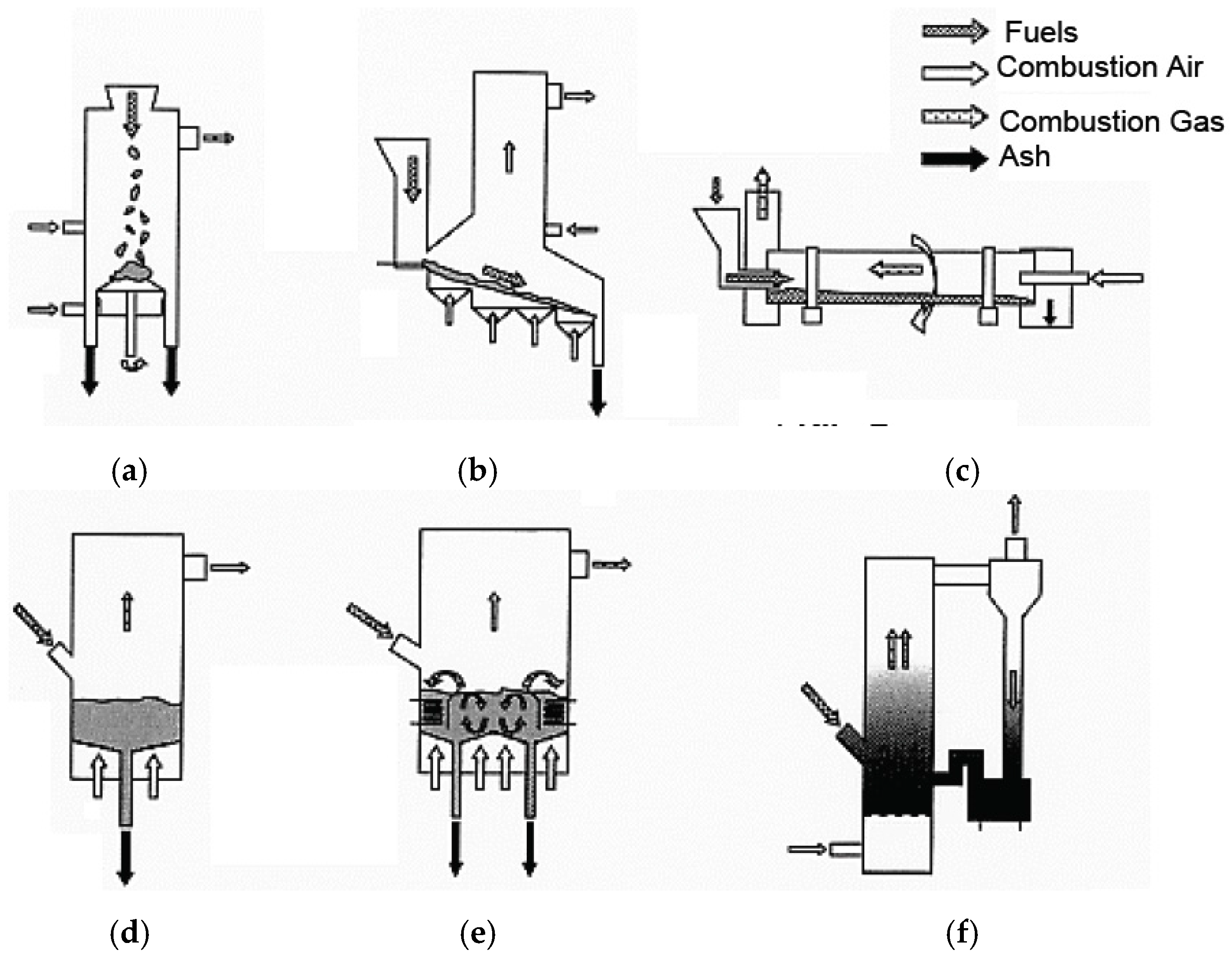
The condition and size of these solid fuels are different, for example, depending on the country and regional area. Therefore, various kinds of combustion systems shown in Figure 1 are utilized such as stoker, kiln, and fluidized bed combustor (BFBC, CFBC) to result in complete combustion, reduction of environmental pollution, and recycling. The properties of municipal and industrial waste and the WTE plant operation have changed as follows due to a large change in the lifestyles of people and in the production styles of industries brought about by technological and economic developments in the past forty years.
- (1)
- Operational change for strict pollution regulation: low O2 or EGR operation to reduce NOx, high-temperature combustion, and an increase in continuous operation to prevent generation of dioxins.
- (2)
- Energy saving and effective heat recovery: more severe corrosive environments have been formed due to the improvement in electric power generation efficiency through high-temperature and high-pressure steam conditions (400–500 °C/3.9–9.8 MPa) of boilers.
- (3)
- Needs to reduce volume of combustion ash and produce non-polluting ash have led to the development of new incineration processes, such as waste pyrolysis gasification, ash melting plants, and oxygen-enriched combustion.
- (4)
- Improvement of total cost performance: reduction of operational cost by advances in maintenance-free operation, such as advanced combustion control, monitoring technologies, and the use of CRMs and CRCs.
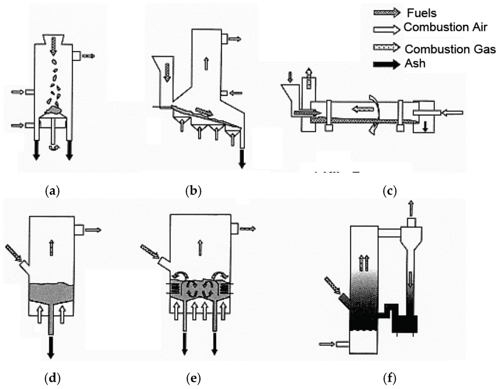
Figure 1.
Schematic illustration of typical combustion systems in WTE and biomass boilers. (a) Fixed Stoker; (b) Moving Stoker; (c) Kiln Furnace; (d) Bubbling Fluidized (BFBC); (e) Inside Cerculated Fluidized Bed (ICFBC); (f) Outside Cerculated Fluidized Bed (OCFBC).
2.3. Corrosion Factors and Corrosion Tendencies in Boilers
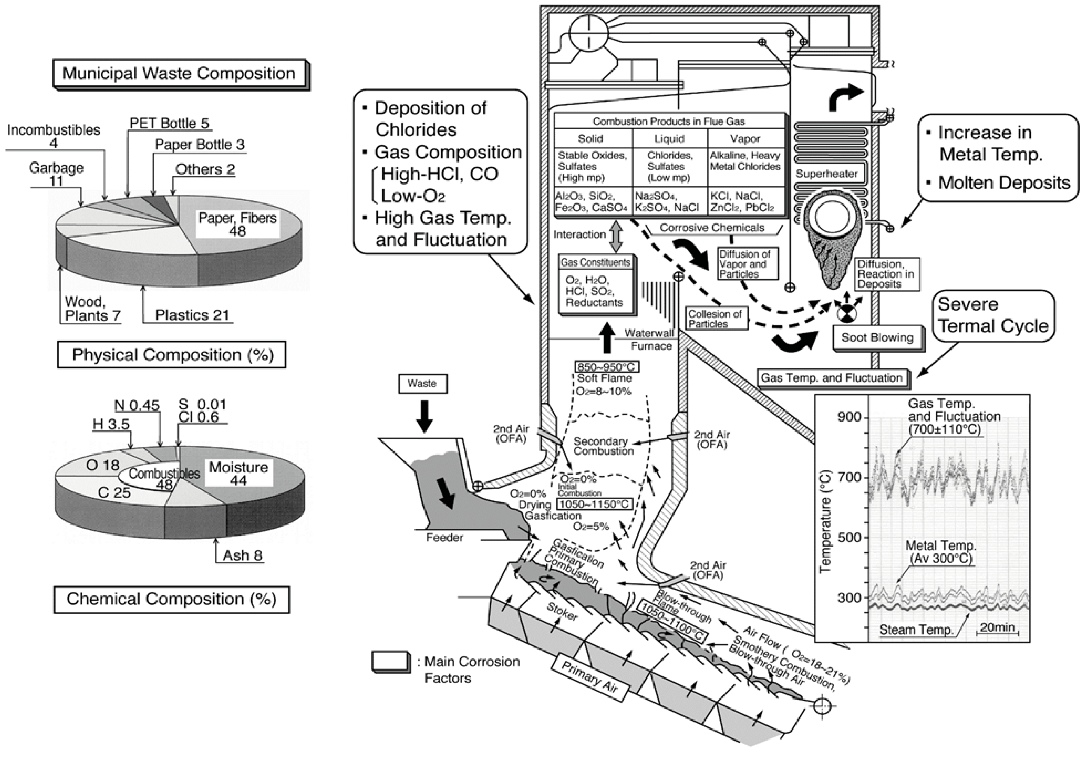
Various substances, both incombustibles as well as combustibles such as wood, paper, plastics, etc., are inhomogeneously mixed in the waste. Therefore, the fluctuation of gas temperature and gas composition containing high amounts of HCl, SOx, O2, and H2O increases compared to fossil fuel boilers. In addition, many LMP ashes contain high concentrations of chloride deposit on the boiler tubes. The corrosive constituent influence on corrosion behavior in boilers burning different fuels are listed in Table 2. The type of corrosion reaction such as chlorination, sulfidation, and oxidation reactions change according to fuel compositions and other operating conditions. This kind of high-temperature corrosion is known to be strongly influenced by LMP of deposits on boiler tubes. Additionally, Figure 2 shows an explanatory drawing of corrosion factors in WTE boilers [2]. Chlorides and sulfates mixtures containing high concentrations of alkali metals (Na, K, etc.) and heavy metals (Pb, Zn, etc.) reduce the melting point of deposits to approx. 300–550 °C. Then, severe HTC is caused in boiler components such as WWTs and SHTs by the LMP deposits. Particularly in the SHTs, the metal temperatures are as high as 300–550 °C, where such deposits are easily melted by the eutectic reaction, and corrosion rates sometimes reach as high as several mm/year or more.
Table 2.
Comparison of combustion ash and deposits properties that influence high-temperature corrosion reactions in typical boiler fuels.

Figure 2.
Schematic illustration of corrosive environment in stoker type WTE boiler [2].
Figure 3 shows the increase in corrosion rates of SHT materials with combustion gas temperatures in this WTE [3]. The gas temperature is very high (850 °C or higher) in the furnace outlet position of WWTs. Therefore, high concentrations of chlorides with LMP are easily deposited, and the corrosion damage is caused mainly by chlorination reactions. Both the adherence of strongly corrosive ash constituents, such as chlorides and sulfates, and the gas temperature fluctuation can be reduced with a reduction in gas temperature. Gas temperatures in the third pass of boiler are usually designed to be less than approx. 650 °C in SHT position. The reduction in gas temperature is effective for stabilization of protective oxide layers on materials. However, the soot blowing used for the purpose of removing deposits on SHT is known to result in the breakdown of protective oxide layers and severe corrosion rates.
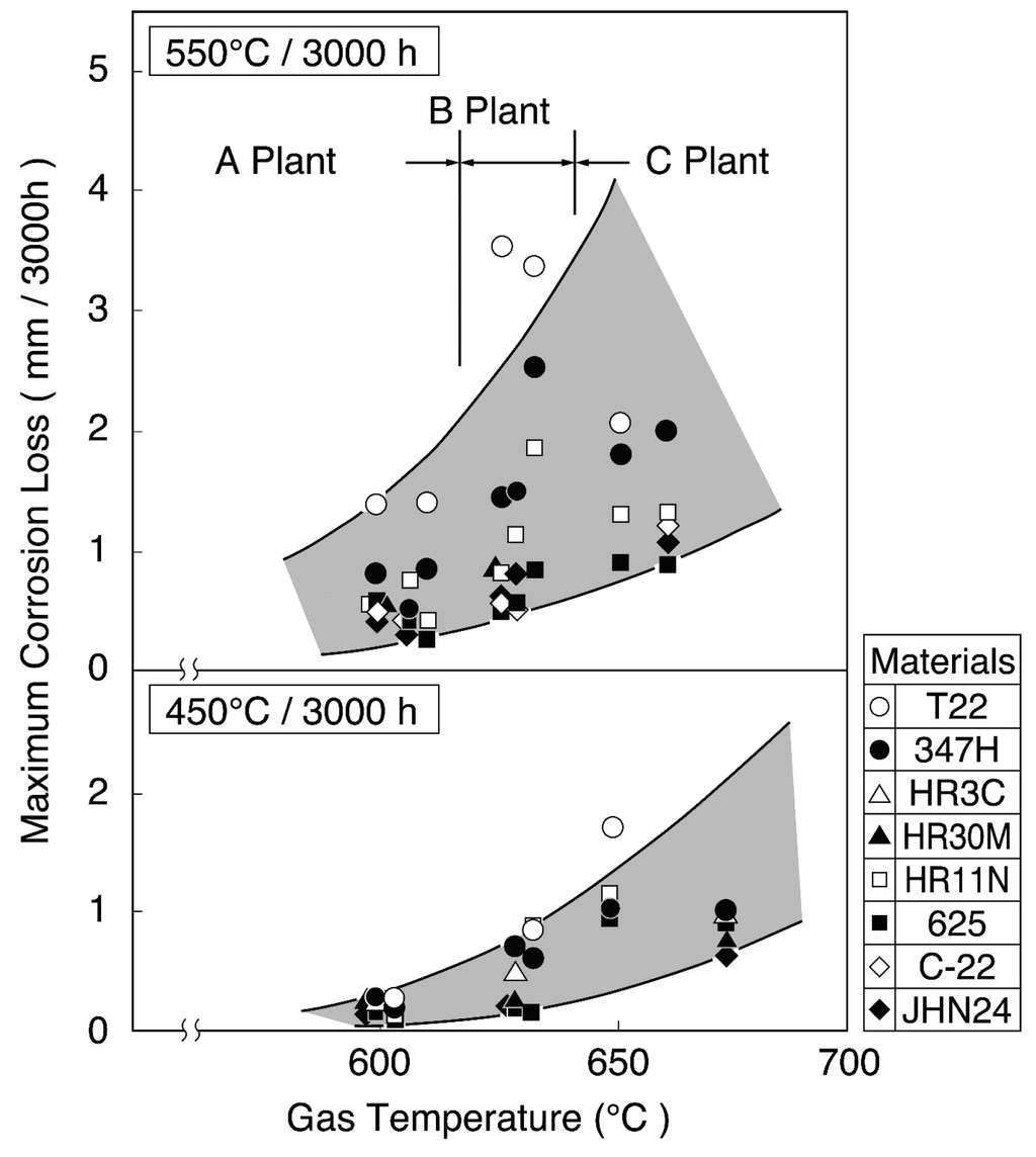
Figure 3.
Change in maximum corrosion thickness loss of superheater materials with gas temperature (Metal temperature: 450 °C, 500 °C) [3].
The corrosion attack of materials is commonly general corrosion, although intergranular or localized corrosion [4] occurs under the existence of molten deposits and loading of stress on even highly CRMs.
3. Application Trends of Corrosion Resistant Materials and Coatings
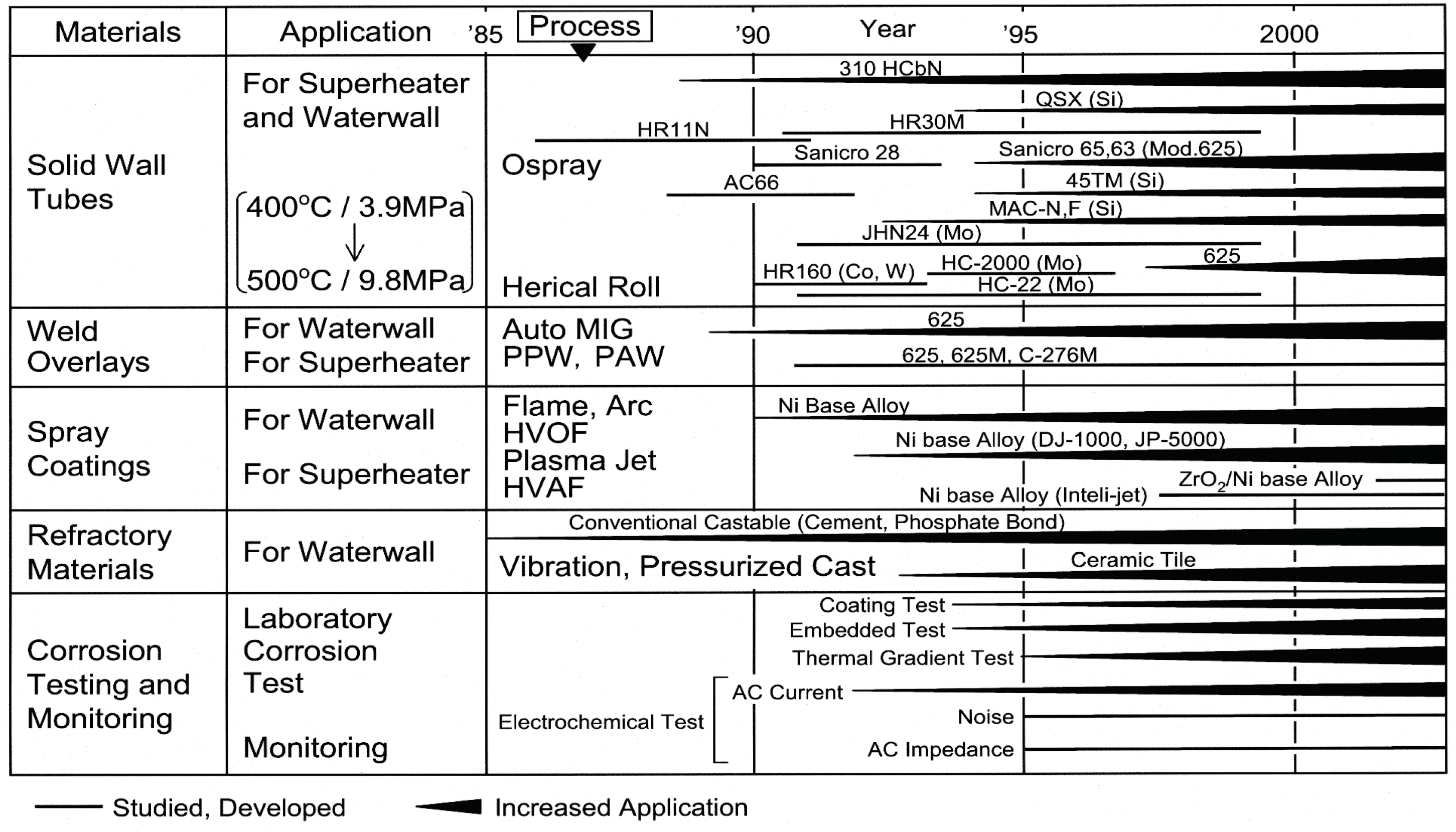
Tube materials of WWTs are commonly carbon steels and CrMo steels to prevent localized corrosion inside the tube. Metal temperatures of WWTs are 250–320 °C depending on water/steam pressure, while surface metal temperatures in SHTs are approximately 300–550 °C. The corrosive environment becomes more severe with the increase in temperature, pressure, and power generation efficiency. Therefore, development and application of CRMs and CRCs are an important issue. The trends of development and application of advanced CRMs and CRCs, as well as evaluation methods for the corrosion resistance and environmental factor, are shown in Figure 4 [2]. Recent trends on application of materials and coatings to biomass/WTE boiler WWTs and SHTs are described as follows.
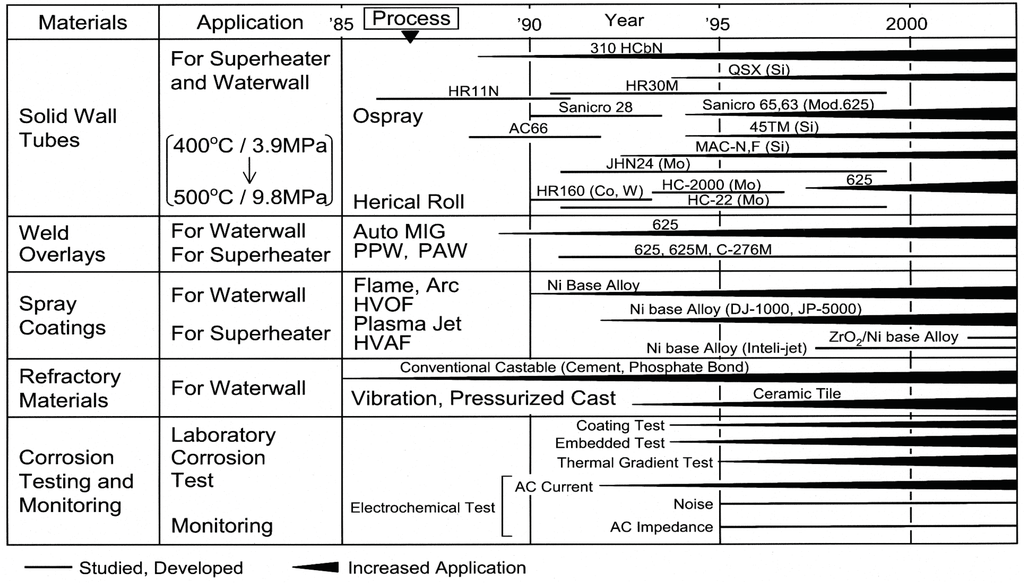
Figure 4.
Development and application of material and coating technologies in WTE plants [2].
3.1. Coatings for Waterwall Tubes
In the severe corrosive environments of the combustion furnace outlet position, corrosion rates of 0.2–4.0 mm/year on WWTs have been observed. The metal temperatures of the WWTs are relatively low as previously mentioned, depending upon the water/steam pressure. Various CRCs such as thermal spray coatings, weld overlays, claddings, and ceramic tile have been commonly used to protect the tube materials of carbon steel and CrMo steels as shown in Figure 5 and in Table 3; here, the main CRCs are actually used as shown in Table 3, and the different class of coatings are described.
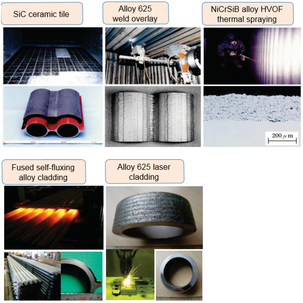
Figure 5.
Corrosion-resistant coatings applied to WTE/Biomass boilers.
Table 3.
Comparison of properties for coatings used in WTE and biomass boiler tubes.
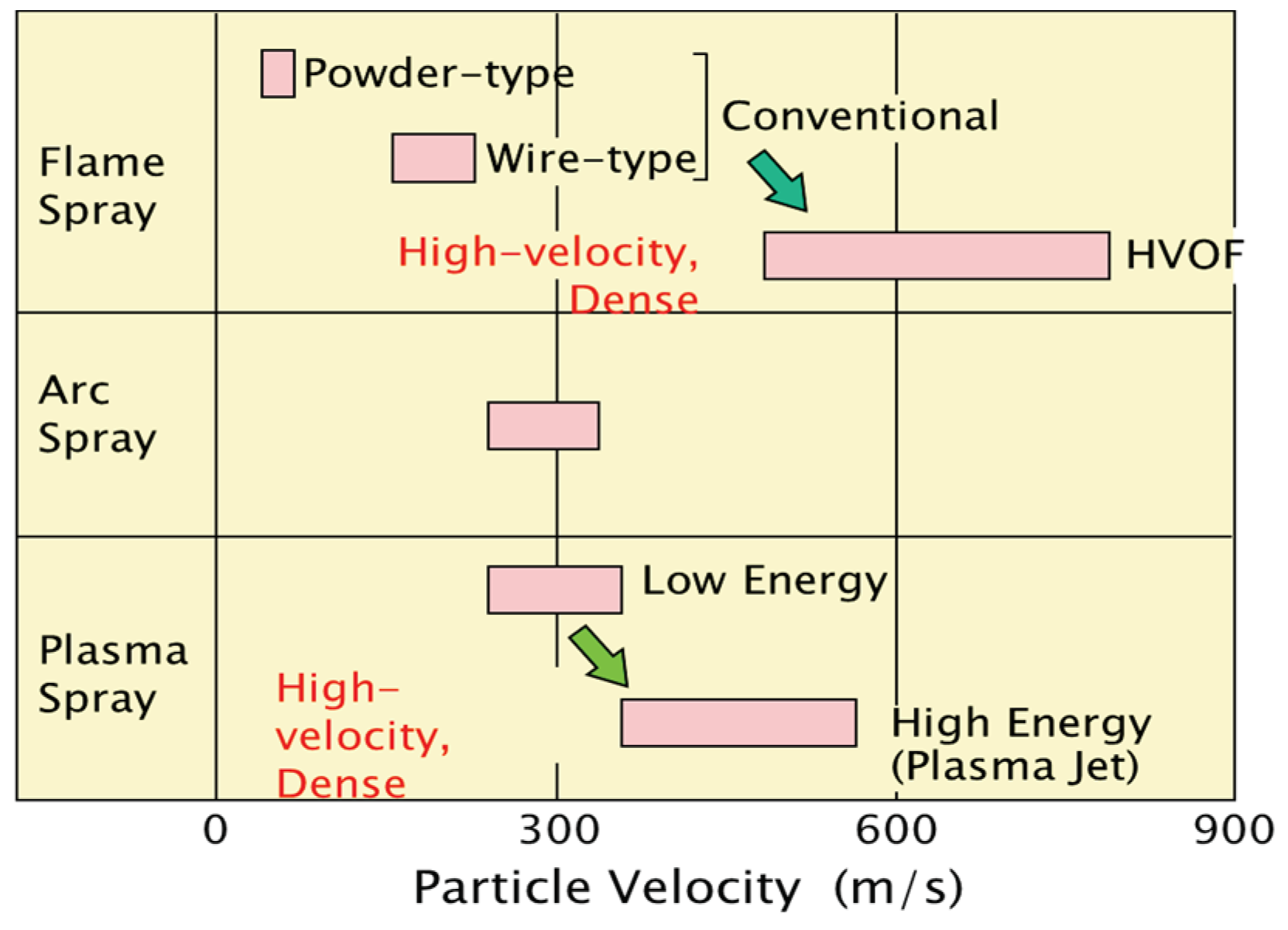
3.1.1. Metal Spray Coatings
Thermal spray coatings of CRMs can be applied on site quickly with a thickness of approximately 150–800 μm depending on the spray processes. Figure 6 shows a comparison of spray speed on various spray processes actually applied to boilers. The application of Al/80Ni20Cr alloy flame spray coating on WWTs actually started around 1985 [5]. Many field tests were conducted in WTE boilers to evaluate the coating durability [6]. Durability of more than three years has been shown in WWTs, but this has not been achieved for SHTs that are in a more severe corrosive environment with high metal temperature in WTE boilers. Of course, the durability is somewhat different depending on individual boiler environments. For example, relatively good durability of spray coatings in WTE plants has been reported as shown below:
- (a)
- Self-fluxing (NiCrSiB) alloy (not fused), Ni base alloys such as alloy 625, and the modified 625 alloys sprayed by the High Velocity Oxygen Fuel (HVOF) process that have a dense film have been shown to have high durability [6];
- (b)
- Corrosion-resistant alloys such as alloy 625 etc. sprayed by the modified plasma spray process are used in European biomass and WTE boilers [7].
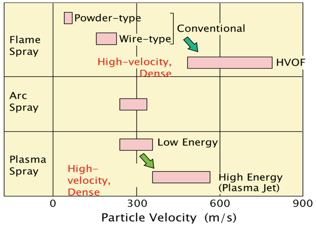
Figure 6.
Comparison of spray speed for various thermal spray systems applied to boilers.
Thermal spray coating system (applied both in-shop and on-site) is selected in accordance with the workability, the duration of repair, the required lifetime, and the total cost performances.
Recently, cold or hot spray processes have been studied for performance and durability [8]; here, coating processes with no defects and strong bonding are important. Future development and applications are expected for the protection of high-temperature corrosion.
As-sprayed coatings are convenient from the viewpoint of working duration and quick application, but durability of such coatings is lower than complete dense coatings due to the existence of open defects in the layer. Figure 7 shows how the bonding strength of such a coating decreases as exposure time increases. It is difficult to completely remove the small size defects such as micro pores and inclusions of oxide. Therefore, it is known that accelerated blister and peel-off formations of the coating layer can occur due to interface corrosion in coating/base material by corrosive gases that have penetrated through such defects. In the deterioration process, thickness loss of the coating layer is rather small at low metal temperature in WWTs. High velocity processes using a relatively fine powder and with a high spraying speed such as HVOF are good for improving bonding strength and durability by reducing of defects as shown in Figure 7 [2]. This has led to an increase in use of the HVOF process.
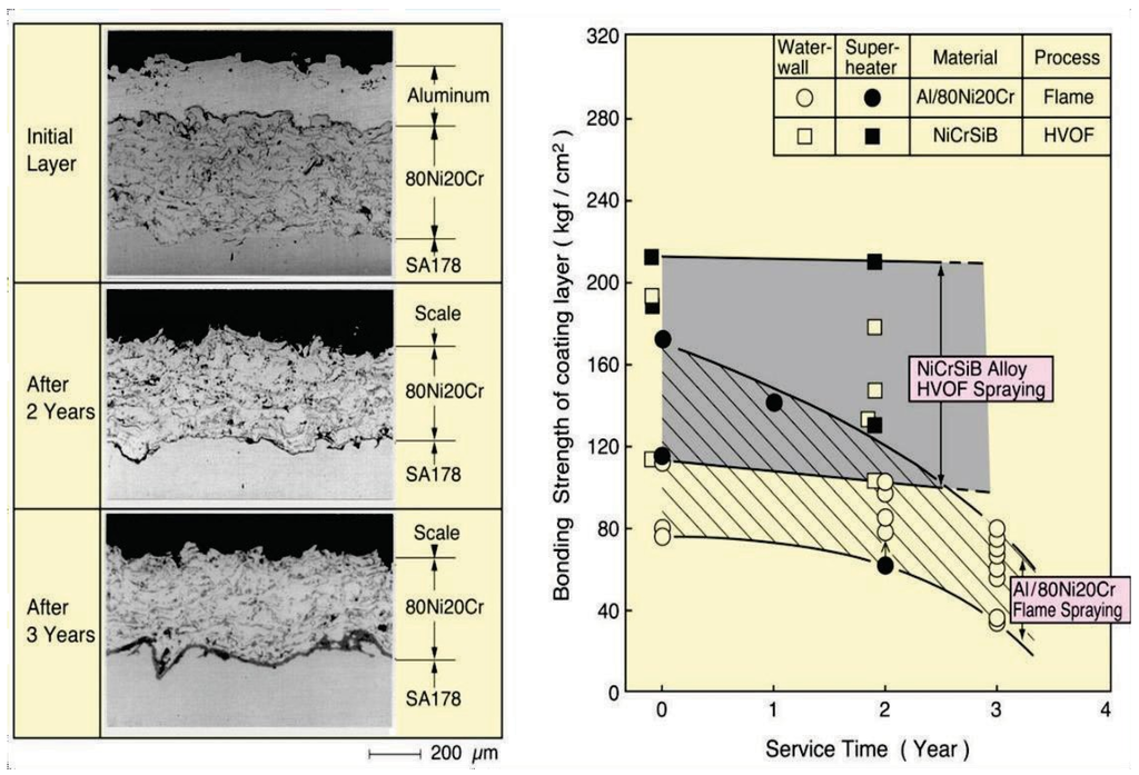
Figure 7.
Change in the bonding strength of on-site flame sprayed Al/80Ni20Cr coating compared with NiCrSiB alloy HVOF coatings due to interface corrosion in WTE boiler waterwalls [2].
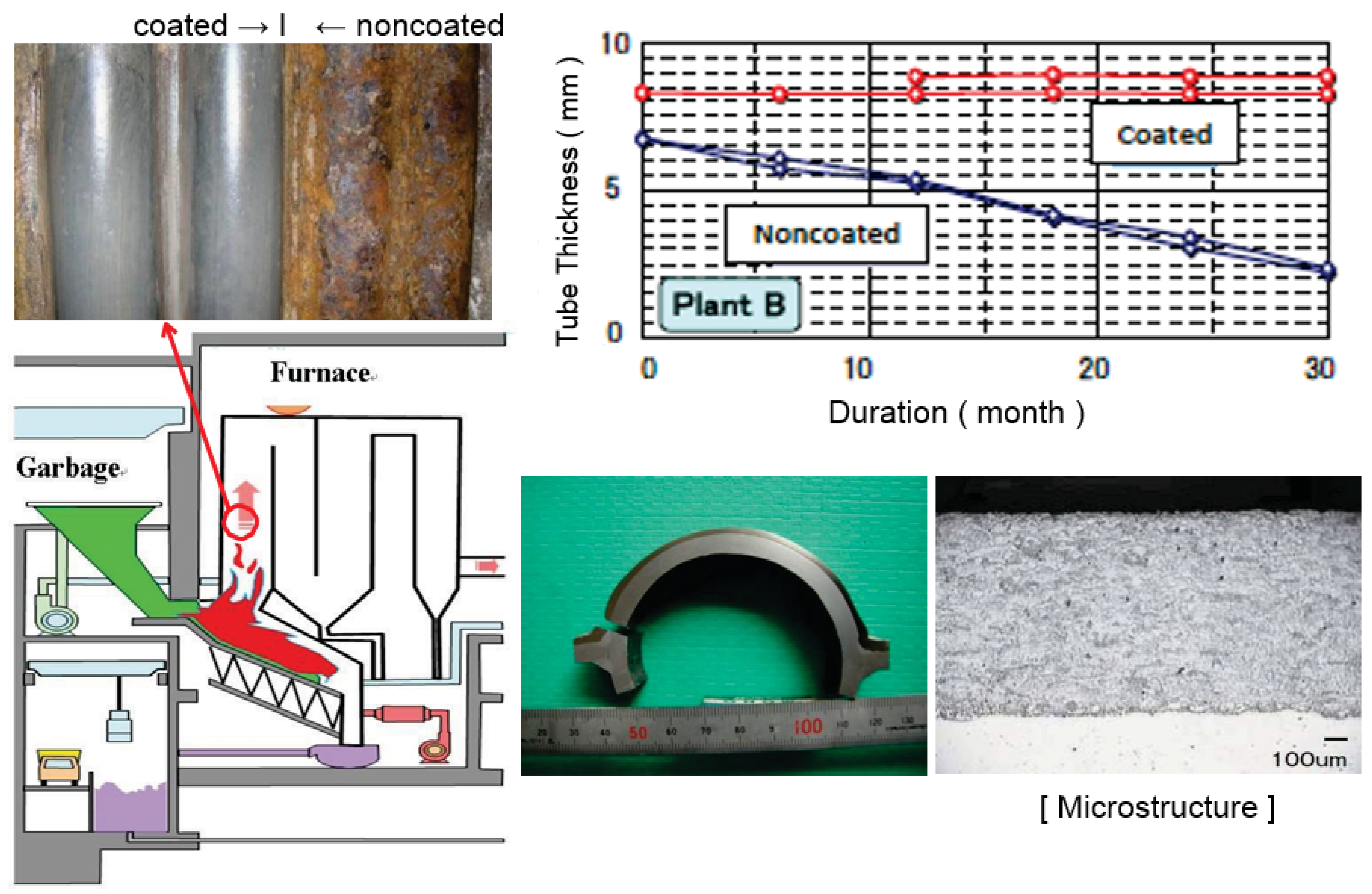
Recently, self-fluxing (NiCrSiB) alloy coatings fused by automatic induction heating has been successfully applied to WWTs. This coating has a homogeneous structure, a chemical bond, no dilution to substrate material, and a smooth surface with 0.5–2.5 mm selectable thickness similar to weld overlay. The lifetime of this coating is excellent compared with spray coatings and have almost the same corrosion rate as alloy 625 overlay as shown in Figure 8 [9]. Large panels for WWTs and SHTs according to the corrosive condition are available according to the shape. Further development in easy applicability is expected in the future.

Figure 8.
Durability of fused self-fluxing alloy coating exposed to WTE waterwalls for 3 years (Thickness Loss: 1 mm/year before coating → 0.1–0.2 mm/3 years after coating).
Harmonization of both material and process is required for selection and development of advanced spray coatings.
3.1.2. Weld Overlays
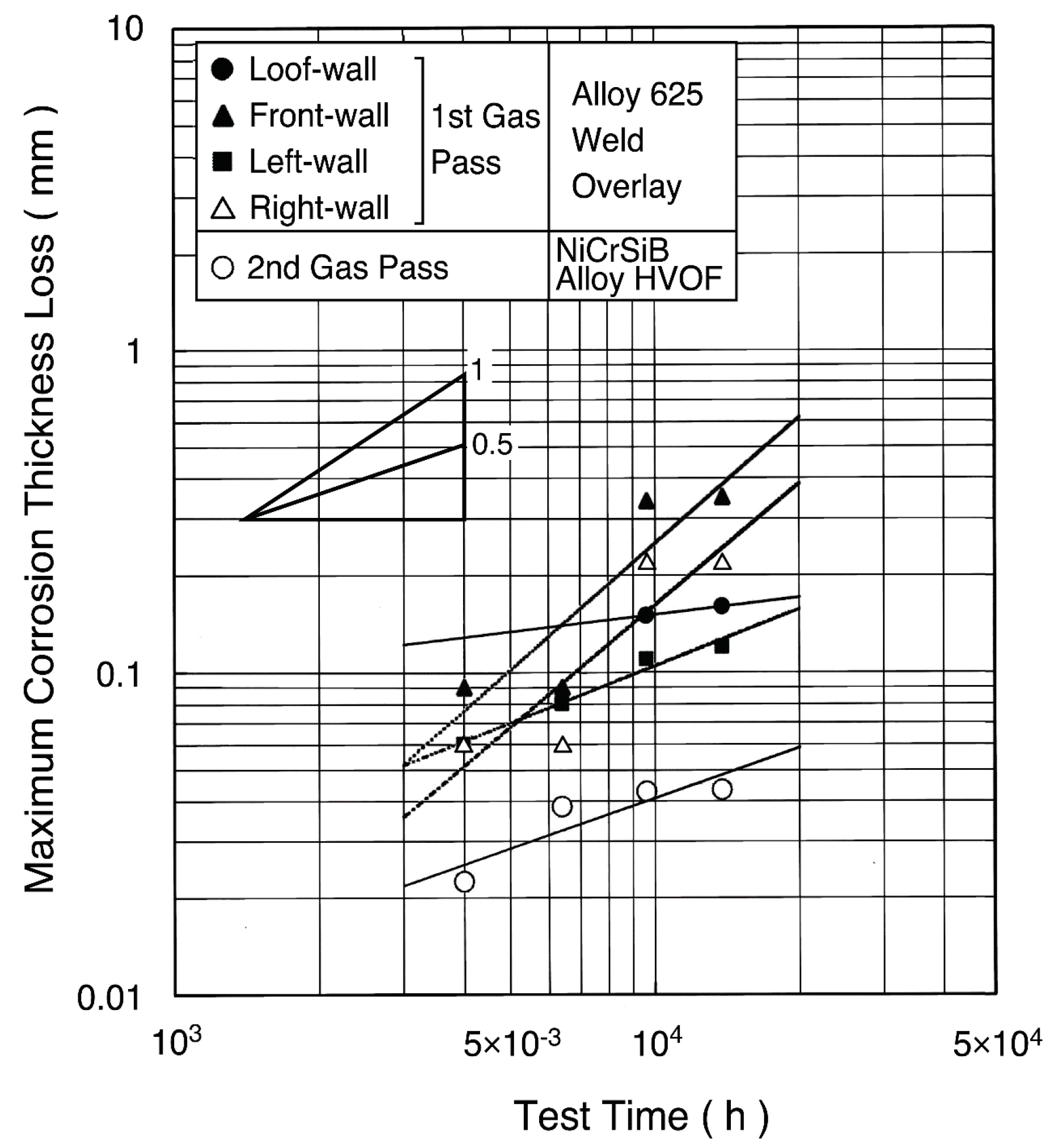
A dense and thick coating layer chemically bonded with the base metal can be obtained by the weld overlays. The durability of alloy 625 weld overlays has been used for 10 years or longer [10]. In many cases for the WWTs, automatic MIG and shielded arc welding have been adopted for both on-shop and on-site applications [11]. For the single tubes for SHTs, MIG welding and plasma powder welding (PPW) have been applied mainly in shop, where tube bending and welding can be performed on overlaid tubes. For the WWTs in the 500 °C/9.8 MPa high efficiency boiler, the maximum corrosion rate of approximately 0.1–0.2 mm/year has been observed from two-year field tests shown in Figure 9 [12].

Figure 9.
Maximum corrosion thickness loss of alloy 625 weld overlay and NiCrSiB alloy HVOF spray coating in waterwall tubes of 500 °C/9.8 MPa WTE boiler [12].
Recently, the pulse-controlled welding method, the so-called cold metal transfer (CMT) laser welding technology, was developed, and applications have progressed. The CMT process can be formed with high quality overlay with less dilution of approximately 5% by control the welding pool temperature to a low level. The laser welding has merits on the quality of coating layers such as low dilution and wide material selection by controlled low heat input, compared with conventional MIG welding. Laser cladding tubes and panels are gradually installed to actual boilers [13]. Additionally, friction welded tubes are developed and being tested in WTE boilers [14]. Further improvement for cost performance and adequate material selection to improve the durability are expected in the future.
With respect to welding materials, various feedstocks such as wires, powders, and more recently cored wires are easily available. Therefore, materials suitable to corrosive environments can be easily supplied, and rapid development of material becomes possible.
3.1.3. Co-Extruded Clad Tubes
Mainly in European countries, co-extruded composite tubes with CRMs as the outer tube, and carbon steels and low alloy steels as the inner tube, have been used for WWTs and SHTs. There have been many application observations of high Cr-high Mo–Ni base alloys such as Sanicro 63 [15]. However, recently, applicability and cost performance have not been comparable with metal spray coatings and weld overlays.
3.1.4. Diffusion Coatings
The history of diffusion coatings applied to boilers are long compared with thermal spray coatings. Therefore, many kinds of diffusion processes such as chromizing, siliconizing, and aluminizing have been evaluated, but application is now rare in WTE and biomass boilers due to the following reasons:
- (a)
- In this kind of coating, the effective thickness is a small amount of approximately 10–100 µm. Additionally, repair is impossible on site.
- (b)
- Composition of the coating layer changes gradually depending on application temperature and exposed duration.
- (c)
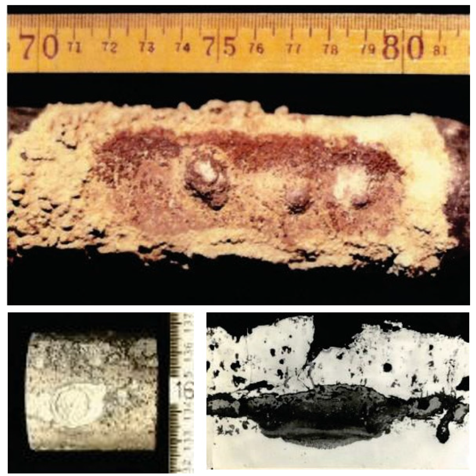
- Some coating layers are brittle by the formation of intermetallic compounds. Therefore, localized corrosion from coating defects sometimes occur in severe corrosive environments. Figure 10 shows an example of localized corrosion formed on aluminized SHT specimens in WTE boilers [16].
 Figure 10. Localized corrosion formed on aluminized CrMo steel of superheater tube specimen exposed to WTE boiler for one year [16].
Recently, new-style diffusion coatings are being developed and applied in WTE boilers to extend durability of studs on WWTs. Such coatings are designed and painted in multiple layers to control surface atmosphere and form corrosion-resistant diffusion layers by heating during services. The good results have been reported [17]. Further development and applications are expected.
3.1.5. Ceramic Refractory Linings and Tile System
Common fireclay linings such as alumina-silica refractory materials are installed in high gas temperature zones of the furnace at approximately 1100 °C. Refractory materials have relatively coarse and inhomogeneous microstructures compared with metallic and ceramic coatings. Therefore, the evaluation and selection of materials is somewhat difficult.
In progress of combustion technologies in biomass/WTE boilers, the high durability of refractory materials and furnace structures becomes a key issue in maintaining the high performance and continuous operation of furnaces. Recently, raw materials of refractories have changed from natural to artificial materials such as high purity silicon carbides (SiC), alumina (Al2O3), etc. to maintain high heat resistance and long durability in severe corrosive environments.
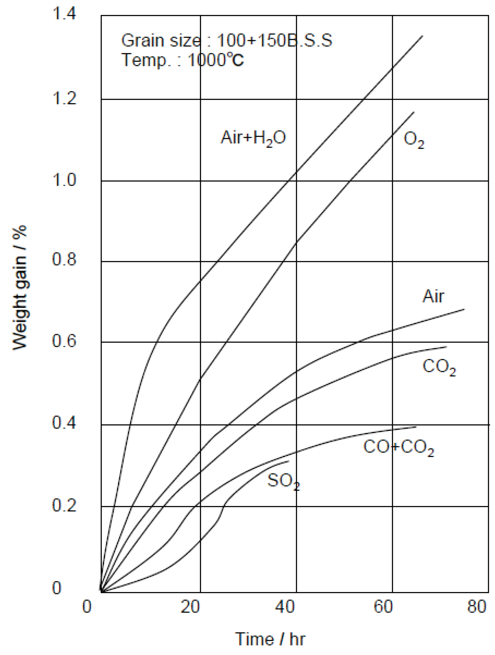
High SiC refractory linings have been used to prevent heavy slagging of molten ash (so-called clinker, melting point: 1200–1300 °C) in high-temperature zones of the furnace, and the clinker can be easily removed without damage of refractory linings. An example of clinker growth in the furnace made by fireclay bricks is shown in Figure 11 [18]. SiC refractories are very hard and have high wear resistance, and so are installed near and along the stoker grate to prevent wear by hard waste. Additionally, they have high thermal shock resistance due to their high thermal conductivity. However, SiC are easily oxidized at 900 °C or more by O2 and H2O, etc. as shown in Figure 12 [19]. As a result of oxidation, SiC particles change to SiO2 that have a larger volume, and damage by swelling and fracture then occurs [20]. Then, SiC refractories are more suitable for water or air cooled furnaces, while high Al2O3 refractories are hard and highly corrosion-resistant too and are sometimes installed in the high gas temperature zone. As shown in Table 4, ceramic tiles that have high SiC content and sometimes high Al2O3 content have good high-temperature performances and are used in many cases in boiler furnaces [21]. The tiles are installed by using special hanging hooks and anchors, or by fixing a bolt and nut with the refractory mortar to the furnace surface of WWTs. The surface temperature of tiles are controlled to approximately 900 °C or lower due to cooling by WWTs. SiC tiles have 200–300 mm size and 25–60 mm thickness to prevent damage due to thermal stresses and chemical reactions during service.
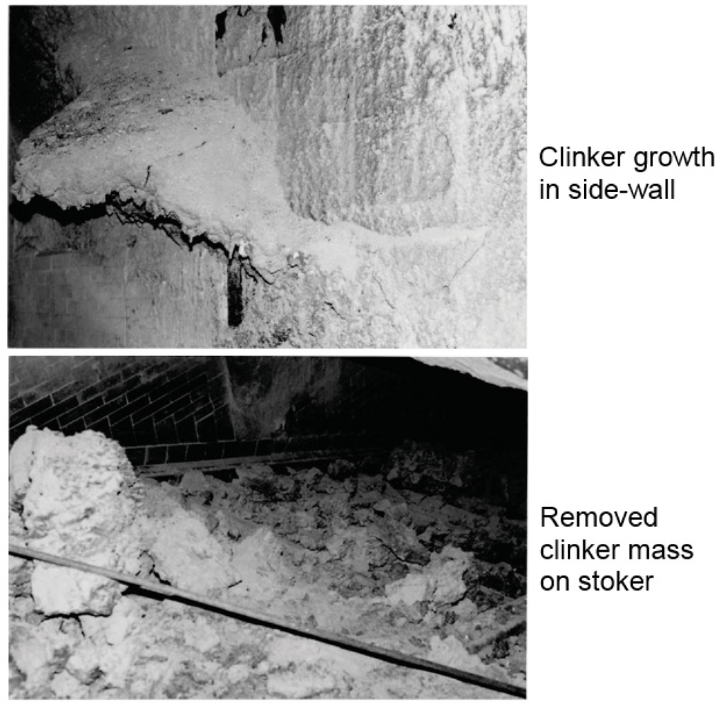
Figure 11.
Example of molten clinker growth formed on high-temperature furnace wall in waste incinerator [18].
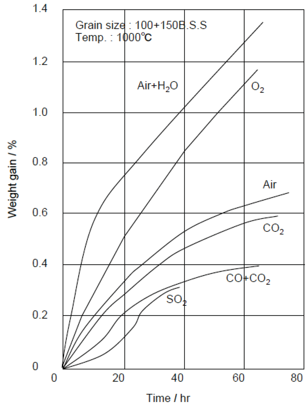
Figure 12.
High temperature oxidation rate of SiC refractories in typical oxidized gases [19].
Table 4.
Comparison of main property of refractories applied to WTE and biomass boiler furnaces [21].
3.2. Corrosion-Resistant Alloys and Coatings for Superheaters
Both corrosion-resistant and heat-resistant characteristics should be taken into consideration in an alloy design of SHTs. Furthermore, good weldability and plastic workability are required to fabricate boiler. Generally, at steam temperatures of approximately 400 °C or lower, carbon steel is used, while, in the high temperature region of more than 400 °C, CrMo steels, austenitic stainless steels, or Ni base alloys are used depending on the corrosive environments. The addition of alloying elements such as Mo, Nb(Cb), Si to Ni–Cr–Fe alloys is considered to be effective in reducing the corrosion rate, as based on field corrosion tests [22]. Additionally, CRCs are applied to SHTs that have higher temperature and a more severe corrosive environment. Many kinds of coating materials such as alloys, cermets, and ceramics are selected for their properties, fabrication abilities and costs, etc., according to each coating process. The various CRMs and CRCs currently used with WTE boilers are described below.
3.2.1. High Cr-High Ni–Fe Base Alloys
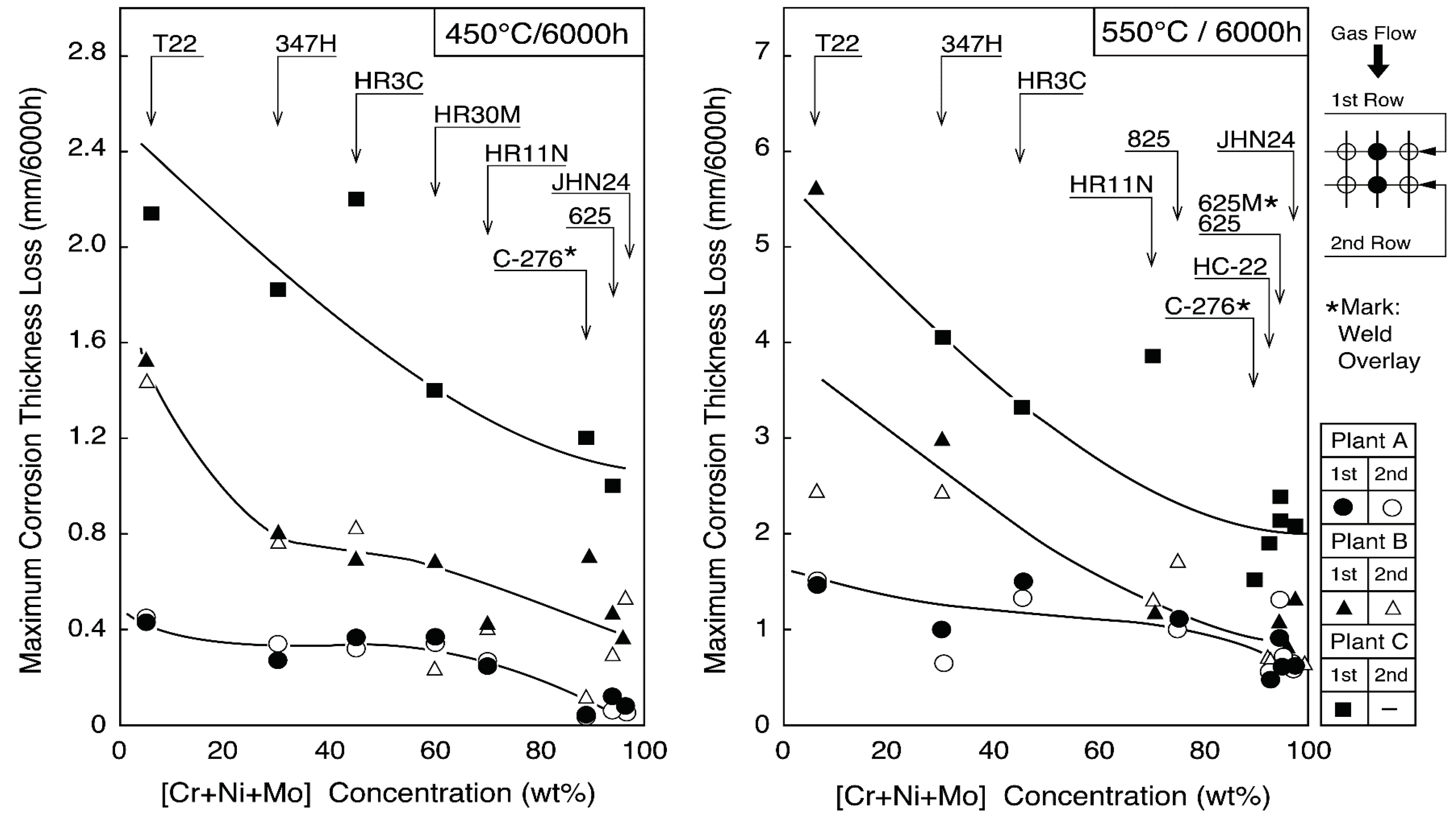
Austenitic stainless steel tubes of 25Cr–14–20Ni steels such as 309S, 310S, 310HCbN, and NF709, which are modified 310S alloys, are mainly used for 400 °C/3.9 MPa boilers for corrosion resistance and cost performance, because the corrosion resistance between Ni–Cr–Fe alloys and Ni base alloys is not so different under the steam conditions below 450 °C, as shown in Figure 13 [23]. Alloy 825, Sanicro 28 (composite tube) of 20–30 Cr–30–40Ni alloys are sometimes used for severe corrosive environments in WTE and biomass boilers [24]. Low-grade austenitic stainless steels of 18Cr–8Ni systems are not used because of a high corrosion rate and sensitivity to intergranular corrosion. Additionally, austenitic stainless steels are rarely used as coatings due to poor weldability and thermal fatigue by a mismatch of thermal expansion coefficient, etc.
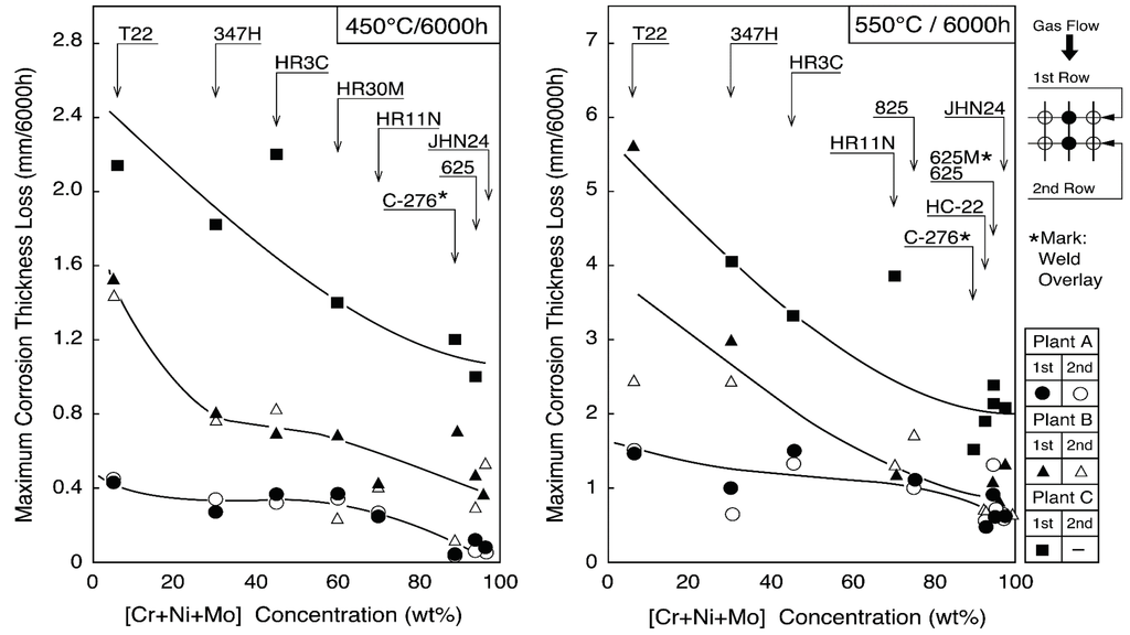
Figure 13.
Change in maximum corrosion thickness loss with [Cr + Ni + Mo] concentration of boiler tube materials exposed for 6000 h at 450 and 550 °C in WTE plants.
3.2.2. High Cr-High Mo–Ni Base Alloys
Alloy 625 and Sanicro 63 (composite tube) have good corrosion resistance under high-temperature steam conditions of 450 °C or higher. Additionally, it is known that HC-22 (Alloy 622), whose Mo content is larger than alloy 625, shows excellent corrosion resistance shown in Figure 13. For these high Mo-containing alloys, the aging deterioration is required to consider high metal temperature applications of more than 500 °C.
Alloy 625 and alloy 622 weld overlays have been applied to many biomass/WTE boiler WWTs and SHTs and have become the most common coatings that are easy to procure.
3.2.3. High Si-High Cr-High Ni Alloys
QSX3 and QSX5 are modified 310S alloys with additions of Si of approximately 3%. It is known that Nicrofer 45TM demonstrates good corrosion resistance in WTE. Furthermore, MAC-F and MAC-N alloys containing 21%–28%Cr, 3.2%–4.2%Si, Ni, and Fe have been applied for four years in the 500 °C/9.8 MPa SHTs in a WTE boiler [25]. The corrosion resistance of materials varies according to the locations in the SHTs where corrosive environments are different. Therefore, it is necessary to make the best selection of the materials in accordance with the corrosive environments.
3.2.4. Cermet Coatings
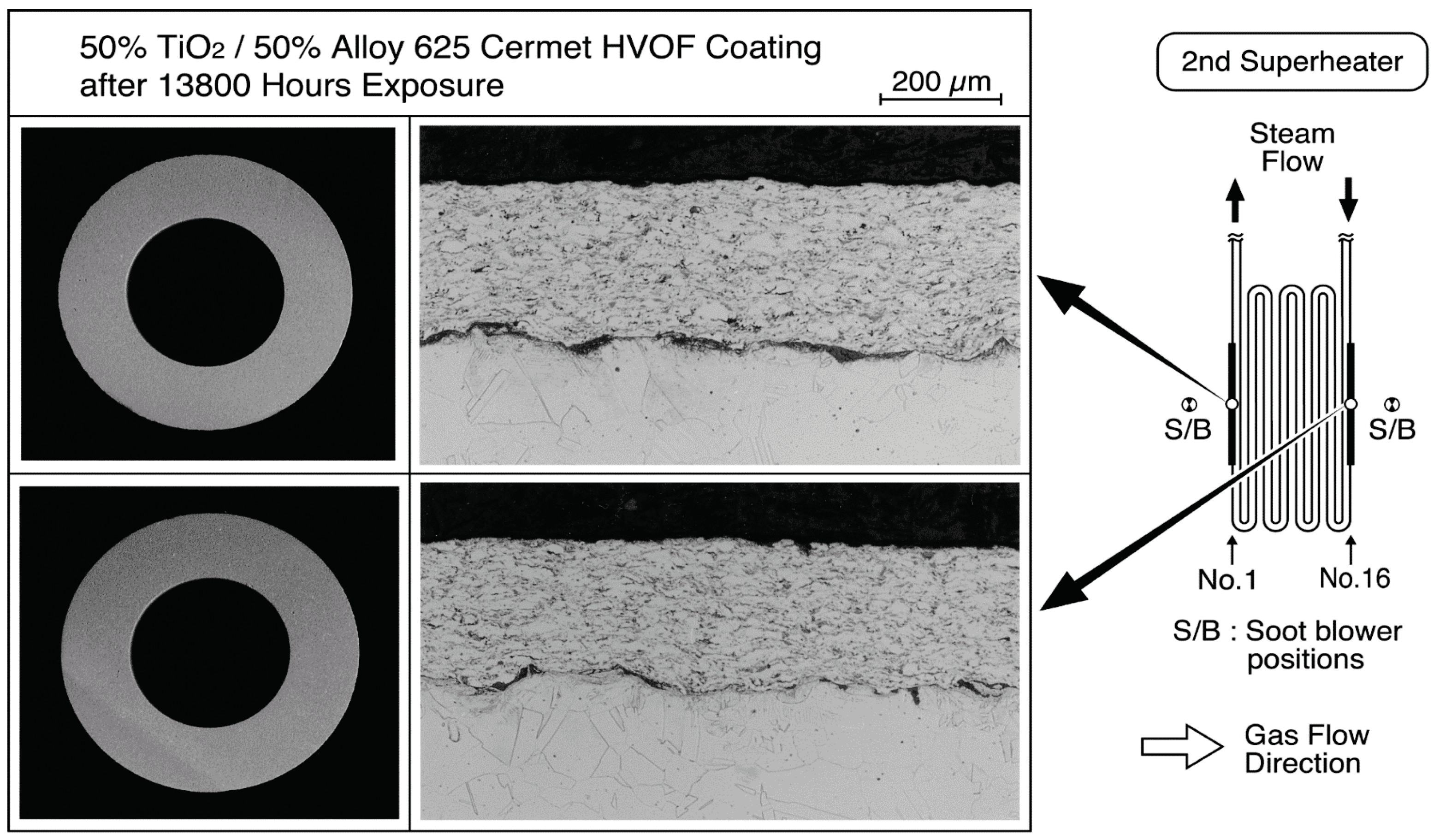
The application of cermet spray coatings has been carried out in a commercial plant that operates under 500 °C/9.8 MPa steam conditions shown in Figure 14. 50% TiO2·50% 625 (TiO2·625). spray coating by HVOF and Cr3C2·75Ni25Cr (CrC·NiCr) spray coating by the ultrasonic plasma jet process on base tubes of 310HCbN were evaluated in secondary SHTs affected by soot blowing at the metal temperature of 432–448 °C for 1.3–2 years [26].
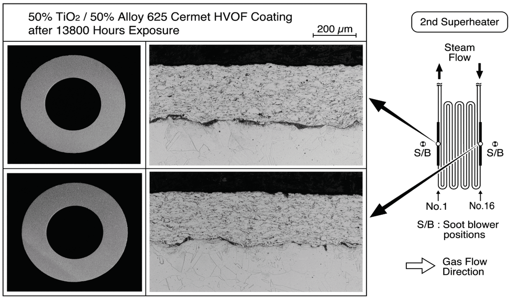
Figure 14.
Microstructures of 50% 625/50% TiO2 cermet HVOF coating layer exposed in superheater tubes (base material: 310HCbN) for 13,800 h in WTE boiler [26].
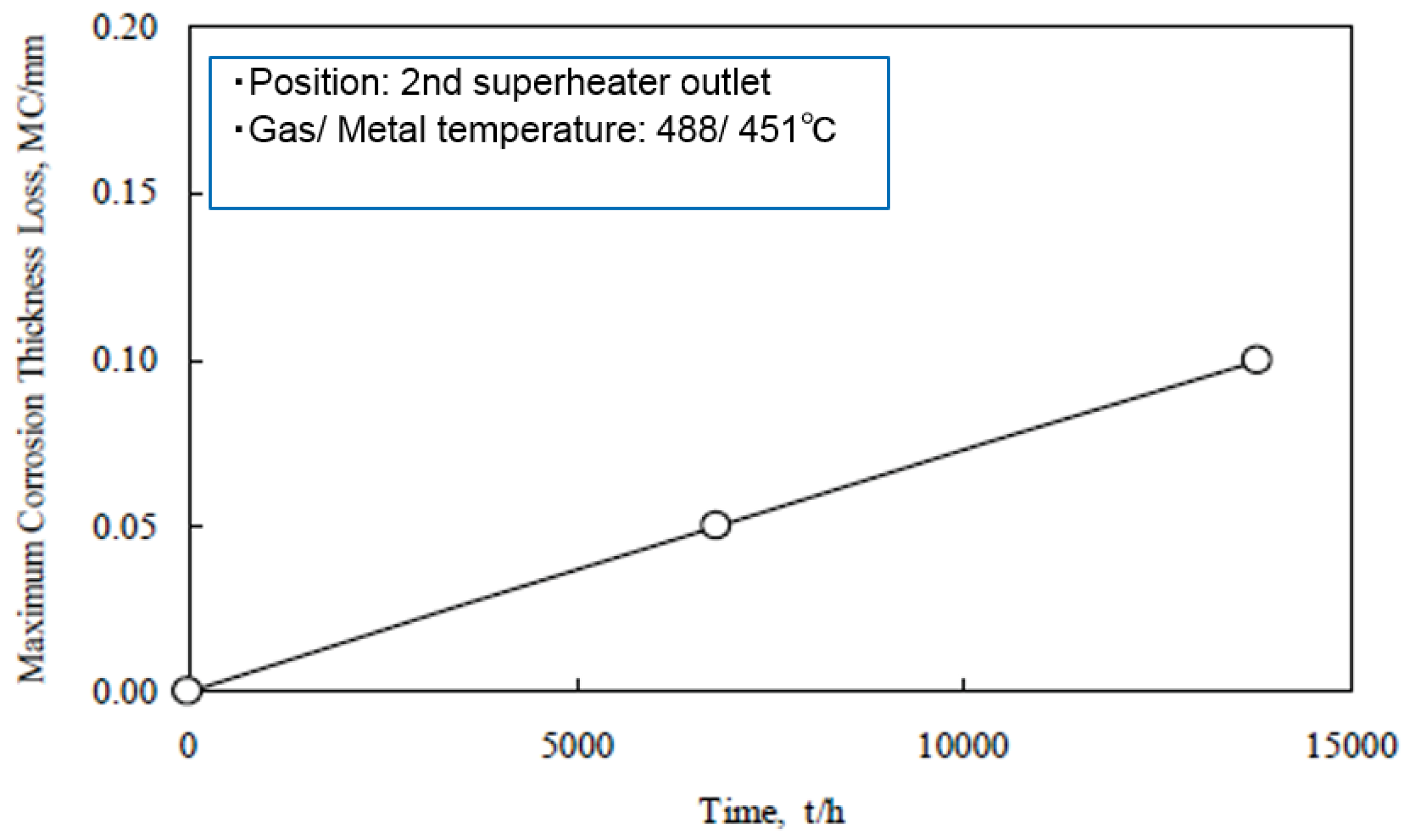
Erosion corrosion (E-C) resistance of the TiO2·625 coating was observed to be high compared with typical CRMs after two years of exposure. The loss of layer depends on a low linear corrosion rate, as shown in Figure 15. The lifetime of this coating was estimated to be approximately four years (27,000 h), with a coating thickness of 200 μm.

Figure 15.
Time dependence of maximum thickness loss of 50% 625/50% TiO2 cermet D-Gun coating (initial thickness: 200 μm) in WTE boiler [26].
On the other hand, the CrC·NiCr coating, used for prevention of E-C in SHTs in WTE boiler, showed peeling with many hexagonal patterned cracks, as shown in Figure 16, particularly in the soot blower affected position after four months of exposure. These cermet-coated layers are corrosion-resistant and hard, and were applied to FBC boilers to reduce E-C and erosion damage as described.
- (a)
- WC–NiCrB cermet coatings sprayed by the high velocity continuous combustion (HVCC) process show good durability in USA biomass BFBC boilers that have severe corrosion and sand erosion conditions at 316 °C [27].
- (b)
- Cr carbide–stainless steel and WC/Cr carbide–NiFe cermet coatings sprayed via the high velocity arc continuous spray (HVAC) or the high velocity air fuel (HVAF) process show good durability in CFBC sludge boilers [28].
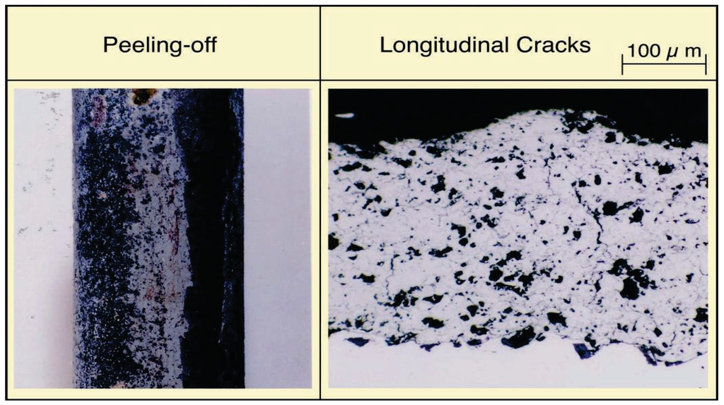
Figure 16.
General view and microstructure of cracked Cr3C2·75Ni25Cr cermet coatings after 4 months exposure in WTE boiler.
3.2.5. Ceramic Coatings
Ceramic coatings were applied to prevent severe corrosion in biomass/WTE boilers and showed good durability in SHTs, but application examples are few because of economical reasons and faults with applicability.
Usually, bond-coatings of CRMs are needed under ceramic layer to control the difference of thermal expansion properties and to keep long durability. Two kinds of dual-layer coatings with alloy 625 or NiCrSiB alloy under-coats and a yttria stabilized zirconia (ZrO2–8% Y2O3, hereinafter abbreviated as YSZ) coating as the top-coat by an on-site ultrasonic plasma jet coat have been exposed in WTE plant [29]. Figure 17 shows a list of the test conditions in the tertiary SHTs of WTE boilers and typical microstructures.
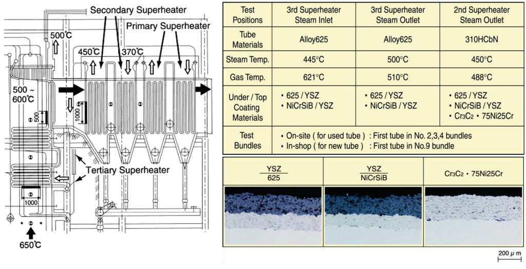
Figure 17.
Test conditions of YSZ/Ni base alloy and Cr3C2·75Ni25Cr cermet coatings and typical microstructures [29].
Figure 18 shows microstructures of the YSZ/625 layer sprayed on-site in the steam inlet portion of tertiary SHTs after 1.3 years of exposure. In the left and right side surfaces inclined to 35° from the upstream-side of the tube, pores and cracks were formed inside the coating layer with a coating thickness reduction. The durability of a conventional single NiCrSiB alloy HVOF layer has been several months in the same positions, and the durability of YSZ double layers was clearly confirmed to have improved. Results show that the durability of each YSZ coatings for E-C damage is large in the order shown below, including the test results of TiO2·625 cermet HVOF coating mentioned before [30]. YSZ/625 ≥ YSZ/NiCrSiB > TiO2·625 Cermet HVOF > CrC·NiCr.
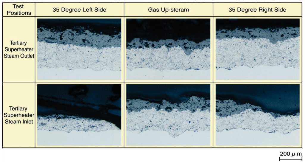
Figure 18.
Typical microstructures of on-site sprayed YSZ/625 layer after 1.3 years of exposure [29].
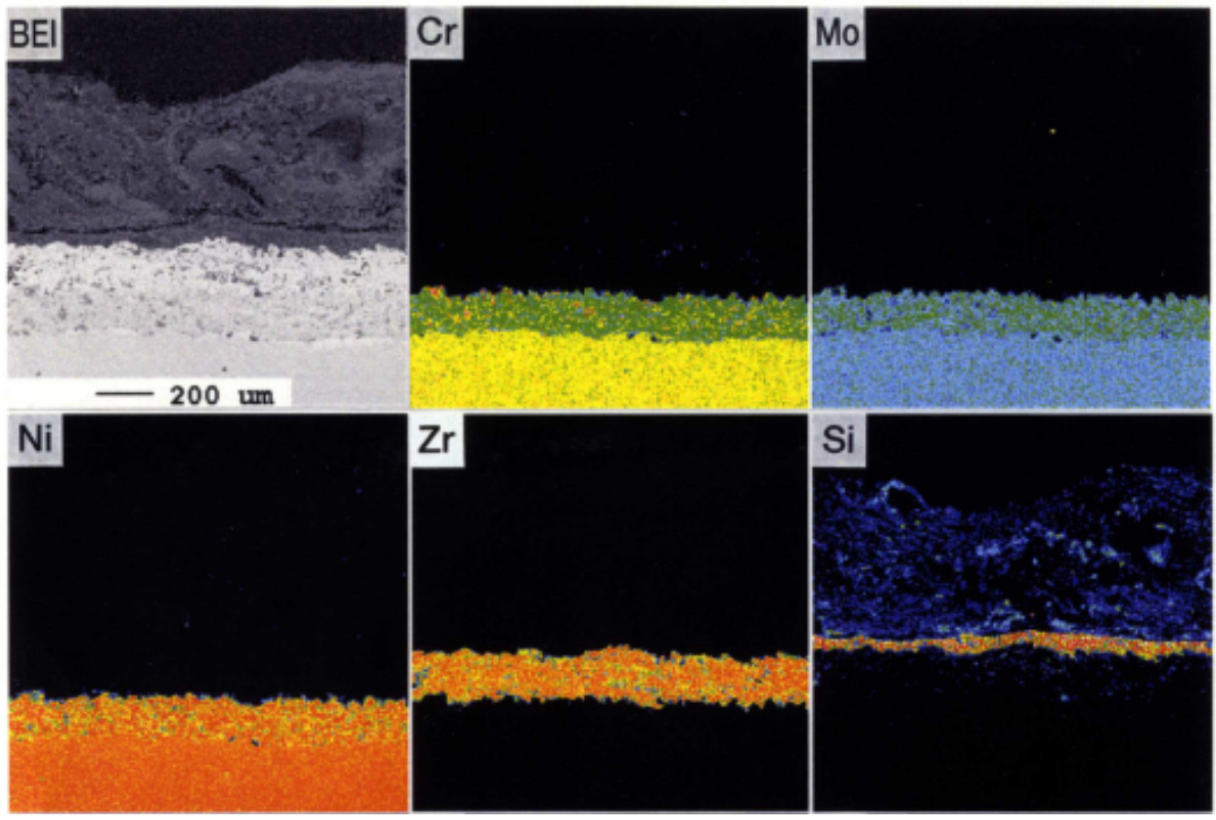
The comprehensive durability evaluation of coatings after 1.3 years of exposure is shown in Table 5. It could be confirmed that YSZ/625 and NiCrSiB spray coatings have a good durability of 3 years or longer. In the EPMA results shown in Figure 19, the amount of penetrated Cl within the under-coated layer and interface of the tube was very small. Additionally, alkali and heavy metals that form low melting point deposits were not found.
Table 5.
Results of lifetime prediction of YSZ/Ni base alloy coatings after 1.3 years of exposure [29].

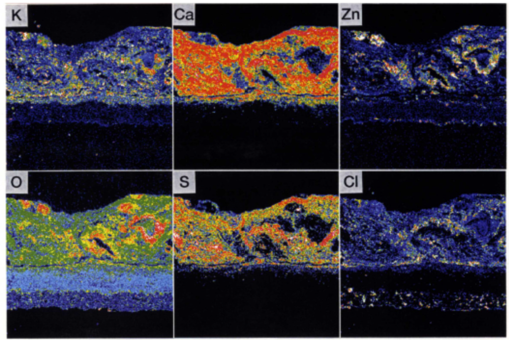
Figure 19.
EPMA images of Sealant/YSZ/625 layers in tertiary superheater inlet position after one year of exposure [29].
4. Deterioration Mechanisms and Design of Coatings
4.1. Formation and Break-down of Protective Oxides Layer
The gas temperature, especially the temperature gradient ΔT (gas temperature−metal temperature), is considered to be the driving force for condensation and deposition of the corrosive vapor components in the gas. The chloride concentration in the deposits shows high concentration at locations where ΔT is large, and there is a tendency to form low melting deposits. Additionally, it is known that the amount of Cl, SO4, alkalis, and heavy metals affect the corrosiveness and the physical properties of the deposits, such as molten phase amount and permeability [31]. The penetration of corrosive gas components through the deposits and the presence of oxidizing constituents such as O2 are considered to be necessary for maintaining the corrosion reactions.
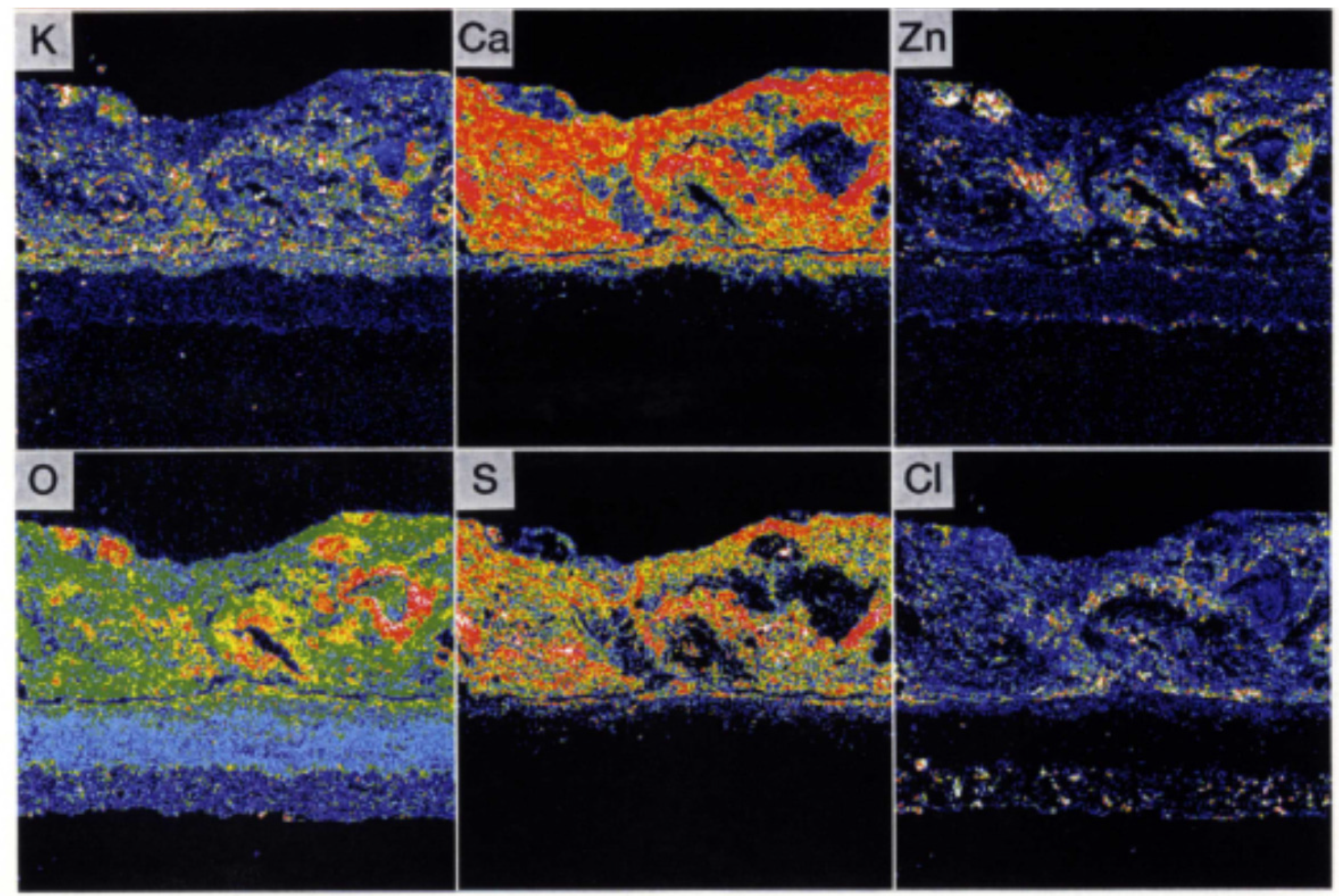
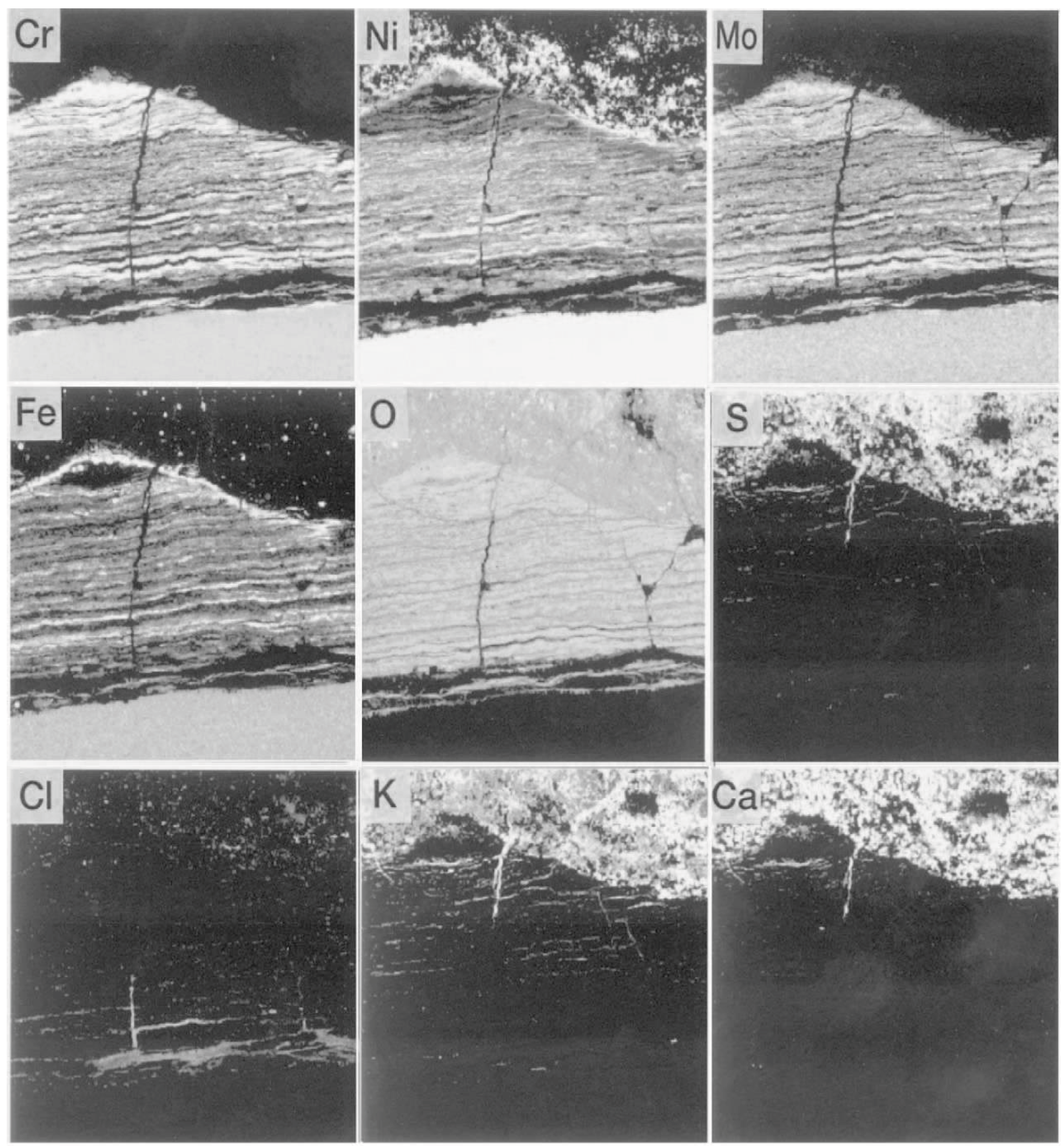
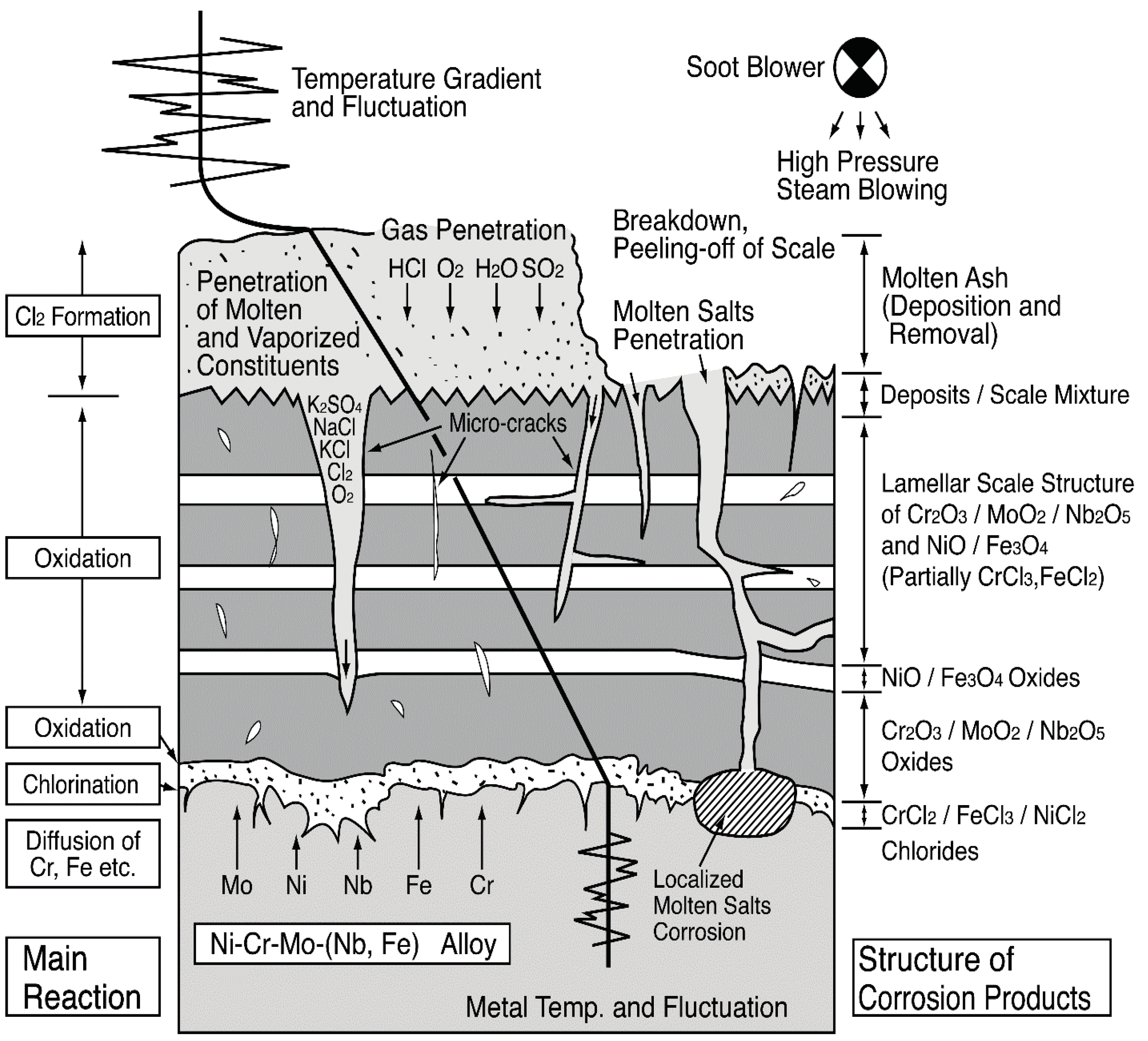
Moreover, severe thermal cycling acts on tube surfaces due to gas temperature fluctuation and use of soot blowers in actual plants. Then, shedding/spalling and regeneration of deposits and protective oxides layer are repeated. Figure 20 shows the EPMA results in the crack-generated position within alloy 625 corrosion scales at the soot blower-affected zone. Partial pressures of Cl and S gases at the corrosion interface are believed to rise under the deposits due to penetration of chlorides, sulfates, etc. through the cracks. This type of corrosion is referred to as “molten salt induced corrosion,” because the gaseous corrosion reaction becomes active, when the amount of deposits increases and a part of the deposits melts [32]. If the protective oxide layer breaks down, corrosive matter penetrates base material, and lamellar structures of scale are formed due to the fluctuation of the partial gaseous condition. Figure 21 shows a schematic explanation of scales and corrosion mechanisms in alloy 625 SHTs. The formation and self-healing of the stable protective oxide layer, which can be considered to be same as ceramic coating film, are important properties of CRMs applied in aggressive corrosive environments. From the configuration and properties of corrosion products distributing as chlorides, sulfides, and oxides from the flue gas side to the corrosion interface, the steady state corrosion is believed to be due to high-temperature gaseous reactions, i.e., chlorination/sulfidation/oxidation. The influence of major factors such as temperature gradient, temperature fluctuation, and molten ash amount on the corrosion rates was examined quantitatively by the laboratory temperature gradient tests [33].

Figure 20.
Breakdown of the protective oxide layer and penetration of corrosive species in alloy 625 superheater tube influenced by soot blowing in WTE boiler [22].
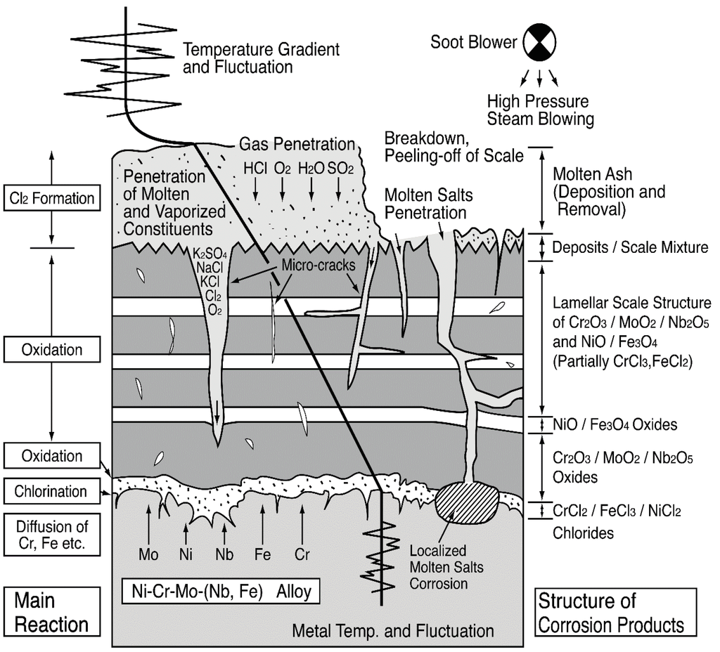
Figure 21.
Schematic illustration of corrosion mechanisms in Ni–Cr–Mo–(Nb, Fe) alloy [33].
4.2. Erosion and Erosion/Corrosion Resistant Materials and Coatings
FBC boilers have grown as major combustion systems for mixed inhomogeneous solid fuels like biomass and waste. Furnace types such as the bubbling fluidized bed combustor (BFBC) and circulated fluidized bed combustor (CFBC) are commonly selected. Typical examples of E-C damages observed in FBC boilers are shown in Figure 22. Solid fuels are burnt, mixing with sand flow that are usually kept at gas temperature of 800–900 °C in the furnace, and erosion or E-C damages have been observed on WWTs, SHTs, and heat exchanger tubes installed in the furnace, influenced by the flow of sand and ash particles. Almost all damages arise due to the combined effect of corrosion and mechanical erosion, after which the damage rates sometimes reach a few mm/month. Erosion and E-C in boilers are classified as the following phenomena.
- (1)
- Accelerated corrosion by damage of the protective oxide layer: Corrosion reactions are increased due to damage of protective oxide layers such as soot blower attack in SHTs and low velocity solid particle erosion in furnace tubes. In this case, an increase in corrosion resistance of materials and the strengthening of protective oxides layers are important to prevent damage.
- (2)
- Mechanical erosion or abrasion of material surfaces: Damage rate is controlled by mechanical fracture of materials arising on the surface. Commonly, the attack of high velocity combustion gas flow including sand and ash solid particles, at few 10–100 m/s, influences this type of damage.
- (3)
- Mixing of corrosion and erosion: This is the intermediate case between (a) and (b), and considered to be influenced by relatively low velocity flue gas of less than a few tens m/s. In many cases of tube damages in actual boilers, this type of accelerated corrosion is believed to occur.
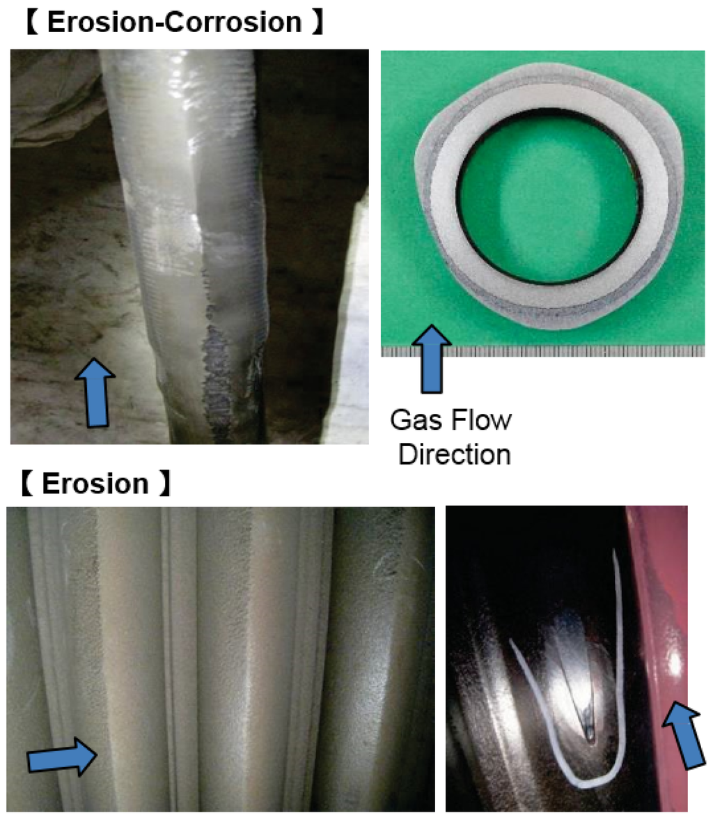
Figure 22.
Example of erosion and erosion-corrosion damages in FBC boilers (arrows show the direction of gas flow).
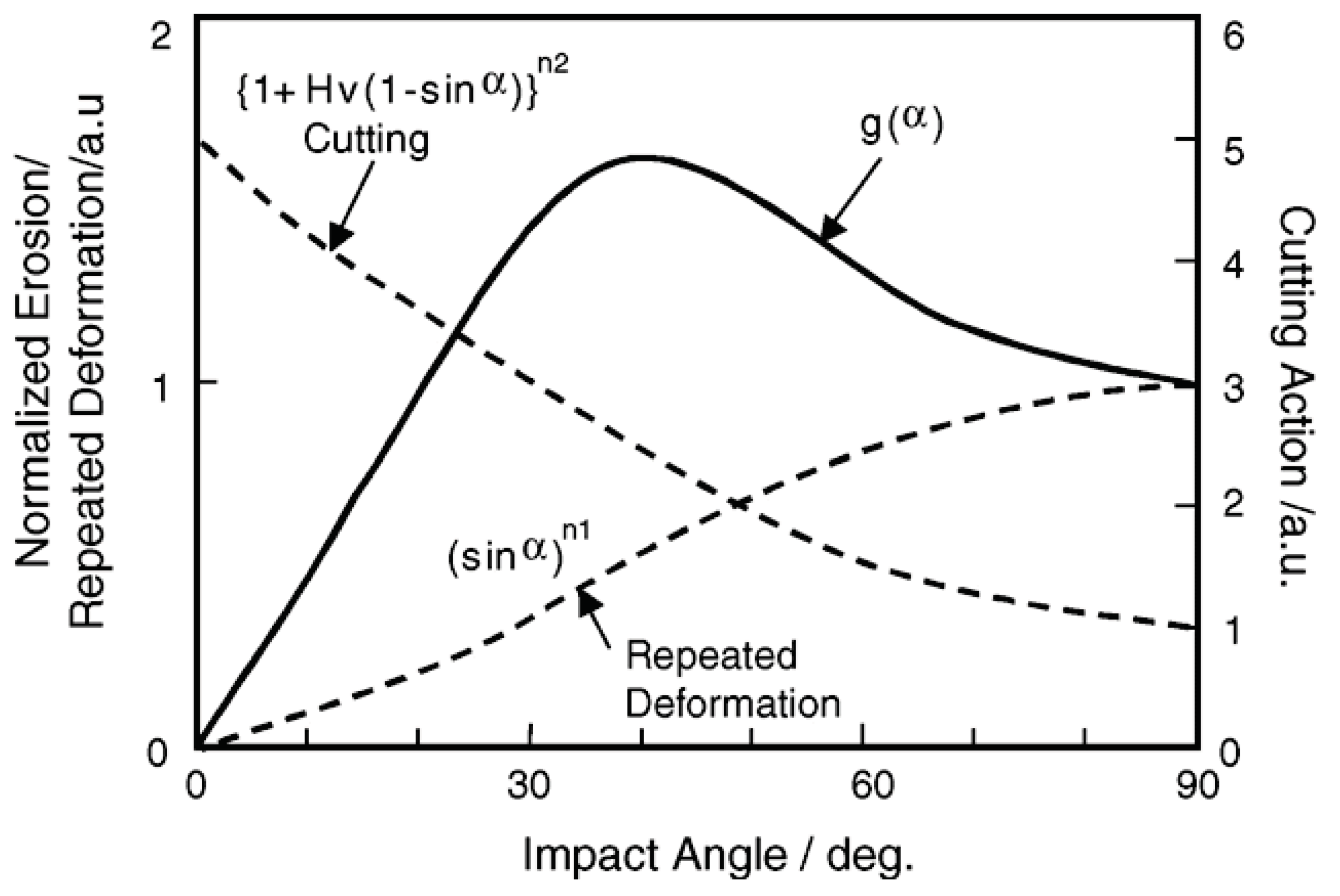
Solid particle erosion damage E(α) in many materials depends on the impact angle α of particles [34], and such a damage rate with arbitrary angle shown in Figure 23 can be expressed by functions of cutting action (sinα)n1 and repeated plastic deformation (1 + HV (1 − sinα))n2 related to the erosion damage at normal angle E90 and hardness HV of target materials.
E(α) = g(α) E90
g(α) = (sinα)n1 (1 + HV (1 − sinα))n2

Figure 23.
Impact angle dependence of erosion rates relating erosion mechanisms in materials having various hardness and toughness [34].
Mechanical erosion is believed to be severe at high particle speeds more than a few 10 m/s, while, at relatively low particle speeds and severe corrosive conditions, mechanisms of damage change to E-C [35]. Of course, the change in the properties of metallic materials or coatings and protective oxide layers, such as the hardness and the fracture toughness at high temperatures, should be considered in the evaluation of coating materials and mechanisms of damage [36].
In the selection of applied coatings for actual FBC boilers, field tests are commonly the most reliable method to estimate the lifetime. For example, many kinds of hard CRC materials, as shown below, have actually been used for common abrasion and especially for FBC boilers.
- (a)
- Weld Overlays: High Cr martensitic stainless steels, hard facing materials.
- (b)
- Laser Claddings: WC–Co, WC–NiCr, Cr carbide–NiCr, WCr carbide–NiCr.
- (c)
- Thermal Sprays: WC–NiCr, WC/Cr carbide–NiCr, WC–NiCrB, NiCrSiB, WC/Cr carbide–NiFe, etc.
- (d)
- Ceramic Linings: Al2O3-rich, SiC-rich refractories and fine ceramics.
Weldability is most important in (a), and many kinds of cermet materials can be applied by using recent cored wire and nano-powder technologies in (b) and (c). To get excellent coating properties, not only the coating process but also the design of the powder and wire are important.
Actual conditions of damages in FBC boilers are difficult to measure and estimate. Therefore, the selection of coatings has been carried out based on investigation results of field tests with consideration of availability and cost performance in many cases. Additionally, E-C phenomena and damage rates are difficult to realize in simplified laboratory tests, as the various contribution of corrosion and erosion are not known. Progress of testing and evaluation technologies are considered to be an important issue to future developments.
4.3. Durability of Alloy and Ceramic Spray Coatings
Figure 24 shows the deterioration mechanisms of spray coating layers used for long periods in the corrosive environments of boilers. Corrosion of the base material and deterioration of coating layer proceed due to penetration of the corrosive gases such as HCl and Cl2 onto the base material/coating interface. Then, “swelling” and/or “crack” of the coating layer occurs, the reduction of adhesive strength is accelerated, and the coating peel finally comes off [6]. Accordingly, dense coating is indispensable for improvement of coating lifetime, and HVOF and HVAF are preferable spray coating processes. The material factors that govern durability are the corrosion rate and open porosity of CRCs, the bonding strength with base materials, the thermal properties such as thermal expansion coefficient, and the residual stress. Such physical properties of the coating are largely dependent on the spraying conditions. Recently, a quantitative evaluation method of lifetime by using small electric resistance methods [37] has been developed and applied to boilers based on these deterioration mechanisms.
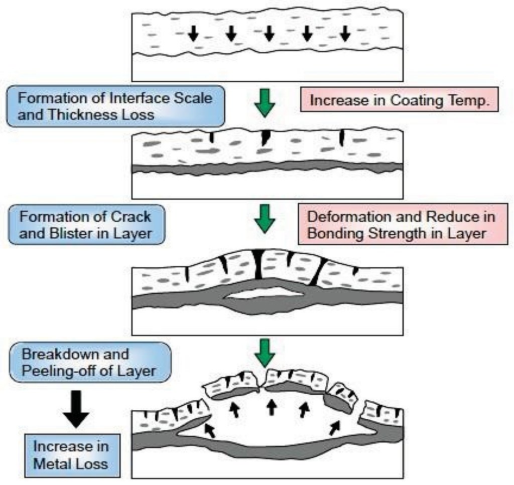
Figure 24.
Deterioration mechanisms of thermal spray coating layer in severe corrosive environment [6].
In the case of dual ceramic coating of YSZ/Ni base alloys, the same mechanisms are clarified in the field tests. The YSZ top layer acts as a diffusion barrier for penetration of corrosive gas components and can improve the lifetime of the under layer as well as base materials.
Practical applications of these ceramic and cermet spray coatings are expected to prevent E-C damages.
5. Summary
Recently, the biomass and WTE plants are required to satisfy many additional performances such as the suppression of pollutants, high efficiency for electric power generation and material recycling. Nowadays, various combustion methods and plant systems have been adopted, and the high-temperature corrosive environment of the plants are becoming greater and diversified. However the main basic factors influencing high-temperature corrosion and E-C are considered to be similar in each plant.
It is believed that the development and application of CRMs and CRCs aim strongly at the right material in the right place with a reasonable total cost. The improvement of performances and lifetime of the high-temperature parts has been supported by the development of CRMs, CRCs, and coating technologies. In order to achieve long lifetime, co-operation between information relating materials and plant design/operation are required.
There are many subjects for future research in aggressive high-temperature corrosion and erosion environments, and it is expected that engineers and researchers will meet the challenge to discover the solution with CRMs and CRCs.
Conflicts of Interest
The author declares no conflict of interest.
References
- Kawahara, Y. Materials for biomass/waste-to-energy boilers. In Handbook of Iron and Steel. The 3rd Volume, Microstructure and Properties of Materials, 5th ed.; The Iron and Steel Institute of Japan: Sendai, Japan, 2014; pp. 436–439. [Google Scholar]
- Kawahara, Y. Recent Trends and Future Subjects on High-Temperature Corrosion-Prevention Technologies in High-Efficiency Waste-to Energy Plants. Zairyo-to-Kankyo 2005, 54, 183–194. [Google Scholar] [CrossRef]
- Kawahara, Y. Formation and Break-down of Protective Oxides Layer in High Temperature Corrosion Resistant Materials Used in Environmental and Energy Equipment. Semin. Text Jpn. Inst. Met. 2006, 99, 46–55. [Google Scholar]
- Uekado, M.; Kamei, Y.; Hujii, K. Effect of Static Stress on High Temperature Corrosion Behavior of Boiler Tubes in Waste Incineration Environment. J. Jpn. Inst. Met. 2002, 66, 576–582. [Google Scholar]
- Kawahara, Y.; Kira, M. Corrosion Prevention of Waterwall Tube by Field Metal Spraying in Municipal Waste Incineration Plants. Corrosion 1997, 53, 241–251. [Google Scholar] [CrossRef]
- Kawahara, Y. Application of High Temperature Corrosion-Resistant Materials and Coatings under Severe Corrosive Environment in Waste-to-Energy Boilers. J. Therm. Spray Technol. 2007, 16, 202–213. [Google Scholar] [CrossRef]
- Hauser & Co GMBH. Manufacturing method of protective coating layer on metallic walls exposed in hot gases. Japanese Patent No. 3150697, 19 January 2001. [Google Scholar]
- Kumar, H.S.; Singh, N. Production of a Nano-Crystalline Ni–20Cr Coatings for High-Temperature Applications. J. Therm. Spray Technol. 2013, 23, 692–707. [Google Scholar] [CrossRef]
- Matsubara, Y.; Sochi, Y.; Tanabe, M.; Takeya, A. Advanced Coatings on Furnace Wall Tubes. J. Therm. Spray Technol. 2007, 16, 195–201. [Google Scholar] [CrossRef]
- Lai, G.; Hulsizer, P. Performance of corrosion-resistant weld overlays in power boilers & kraft recovery boilers. In Proceedings of the Stainless Steel World/99 Conference, Den Haag, The Netherlands, 15–17 November 1999; pp. 681–688.
- Brennan, M.S.; Gassmann, R.C. Laser Cladding of Nicker and Iron Base Alloys on Boiler Waterwall Panels and Tubes; CORROSION/2000, Paper No. 235; NACE: Orlando, FL, USA, 2000. [Google Scholar]
- Kawahara, Y.; Orita, N.; Takahashi, K.; Nakagawa, Y. Demonstration Test of New Corrosion-resistant Boiler Tube Materials in High Efficiency Waste Incineration Plant. TETSU-TO-HAGANE 2001, 87, 544–551. [Google Scholar]
- Heath, G.R.; Tremblay, A. Extending the Lifetime of Boiler Tubes Under Severe Conditions with Advanced Coatings in Waste and Coal Fired Power Plants. In Presented at PowerGen Asia 2014, Kuala Lumpur, Malaysia, 10–12 September 2014.
- Sakata, F.; Tamashita, T.; Sonoda, A. Study of friction surfacing technology to enhance the possibility of high temperature incineration for energy saving. Tsukuru 2003, 47–50. [Google Scholar]
- Wilson, A.; Forsberg, U.; Lunderg, M.; Nylöf, L. Composite Tubes in Waste Incineration Boilers. In Proceedings of the Stainless Steel World/99, Den Haag, The Netherlands, 15–17 November 1999; pp. 669–678.
- Kawahara, Y. Controlling Factors of Localized Corrosion in Boiler Combustion Gas Environment. Oxid. Met. 2016, 85, 127–149. [Google Scholar] [CrossRef]
- Galetz, M.C.; Montero, X.; Mollard, M.; Günthner, M.; Pedraza, F.; Schütze, M. The role of combustion synthesis in the formation of slurry aluminization. Intermetallics 2014, 44, 8–17. [Google Scholar] [CrossRef]
- Kawahara, Y. Improvement of Durability and Evaluation Technologies for Refractories in Waste Incinerator and Industrial Boiler. TAIKABUTU 2009, 61, 320–334. [Google Scholar]
- Lea, A.C. The oxidation of silicon-carbide refractory materials. J. Soc. Glass Technol. 1949, 33, 27–50. [Google Scholar]
- Iemura, I. Refractory materials for refuse incinerator. Shinagawa Giho 1979, 23, 73. [Google Scholar]
- Strach, L.; Lane, L.; Wasyluk, D.T. Experience with Silicon-Carbide Tiles in Mass-Fired Refuse Boilers; CORROSION/93, Paper No. 219; NACE: Houston, TX, USA, 1993. [Google Scholar]
- Kawahara, Y. High temperature corrosion mechanisms and effect of alloying elements for materials used in waste incineration environment. Corros. Sci. 2002, 44, 223–245. [Google Scholar] [CrossRef]
- Kawahara, Y.; Nakamura, M.; Tsuboi, H.; Yukawa, K. Evaluation of New Corrosion Resistant Superheater Tubings in High Efficiency Waste-to-energy Plants. Corrosion 1998, 54, 576–589. [Google Scholar] [CrossRef]
- Haggblom, E.; Nylöf, L. Materials for Advanced Power Engineering, Part II; Coutsouradis, D., Ed.; Kluwer Academic Publishers: Dordrecht, The Netherlands, 1994; p. 1597. [Google Scholar]
- Kawahara, Y.; Sasaki, K.; Nakagawa, Y. Development and Application of High Cr-high Si–Fe–Ni Alloys to High Efficiency Waste-to-Energy Boilers. J. Jpn. Inst. Met. 2007, 71, 76–84. [Google Scholar] [CrossRef]
- Fukuda, Y.; Kawahara, Y. Evaluation of Corrosion Resistance of Waste Incinerator Superheater Tubes Coated by High Velocity Thermal Spray. J. Jpn. Inst. Met. 2002, 66, 563–568. [Google Scholar]
- Dooley, R.; Wiertel, E. A Survey of Erosion and Corrosion Resistant Materials being used on Boiler Tubes in Waste-to-Energy Boilers. In Proceedings of the 17th Annual North American Waste-to-Energy Conference (NAWTEC17-2334), Chantilly, VA, USA, 18–20 May 2009.
- Technical Data of Integrated Global Services Inc.; Integrated Global Services Inc.: Richmond, WV, USA, 2014.
- Kawahara, Y.; Nakagawa, Y.; Kira, M.; Sakurada, T.S.; Kamakura, H.; Imaizumi, Y. Life Evaluation of ZrO2/Ni Base Alloy Plasma-Jet Coating Systems in High Efficiency Waste-to-Energy Boiler Superheaters; CORROSION/2004, Paper No. 04535; NACE: New Orleans, LA, USA, 2004. [Google Scholar]
- Kawahara, Y. Application of High-Temperature Corrosion-Resistant Ceramics and Coatings under Aggressive Corrosion Environment in Waste-to-Energy Boilers. In Handbook of Advanced Ceramics, 2nd ed.; Somiya, S., Ed.; Academic Press/Elsevier: Waltham, MA, USA, 2013; pp. 807–836. [Google Scholar]
- Kawahara, Y.; Kira, M. Effect of Physical Properties of Molten Deposits on High Temperature Corrosion of Alloys in Waste Incineration Environment. Zairyo-to-Kankyo 1997, 46, 8–15. [Google Scholar] [CrossRef]
- Zahs, A.; Spiegel, M.; Grabke, H.J. The influence of alloying elements on the chlorine-induced high temperature corrosion of Fe-Cr alloys in oxidizing atmospheres. Mater. Corros. 1999, 50, 373–393, 561–578. [Google Scholar] [CrossRef]
- Kawahara, Y. Evaluation of high-temperature corrosion life using temperature gradient corrosion test with thermal cycle component in waste combustion environment. Mater. Corros. 2006, 57, 60–72. [Google Scholar] [CrossRef]
- Oka, Y.I.; Okamura, K.; Yoshida, T. Practical estimation of erosion damage caused by solid particle impact. Wear 2005, 209, 95–101. [Google Scholar] [CrossRef]
- Notomi, A. High Temperature Erosion and Wear Resistant Material. Mater. Jpn. 1997, 36, 697–702. [Google Scholar] [CrossRef]
- Isomoto, Y.; Kawanishi, T.; Kawahara, Y.; Yosihara, M. Characteristics and Damage Mechanisms of Sand Erosion for Self-Fluxing Alloy Coatings. J. Jpn. Inst. Met. 2013, 77, 231–236. [Google Scholar] [CrossRef]
- Ohoba, S.; Yoshikawa, Y.; Sasaki, K.; Kawahara, Y. Application and Life-time Evaluation of Metal Spray Coatings for Fire-Side Corrosion of Boiler Waterwall. J. Jpn. Boiler Assoc. 2008, 348, 14–23. [Google Scholar]


© 2016 by the author; licensee MDPI, Basel, Switzerland. This article is an open access article distributed under the terms and conditions of the Creative Commons Attribution (CC-BY) license (http://creativecommons.org/licenses/by/4.0/).