Abstract
Ultrasonic vibration-assisted grinding using cubic boron nitride (CBN) wheels has emerged as an effective approach for improving surface integrity and machining efficiency in hard-to-machine materials. However, achieving a desirable balance between surface roughness and material removal rate remains a critical challenge due to their inherently conflicting nature. In this study, a multi-objective optimization framework is proposed to simultaneously minimize surface roughness (Ra) and maximize material removal rate (MRR) in external cylindrical CBN grinding performed on a computer numerical control (CNC) milling machine under ultrasonic vibration assistance. Gaussian process regression models were first developed to accurately represent the nonlinear relationships between machining parameters and the target responses. These surrogate models were subsequently integrated with the non-dominated sorting genetic algorithm II (NSGA-II) to generate a set of Pareto-optimal solutions. The convergence behavior of the optimization process was evaluated using the hypervolume indicator, confirming fast and stable convergence. The resulting Pareto front clearly illustrates the trade-off between Ra and MRR, and a knee point solution was identified as a practical compromise for industrial application. The optimized results demonstrate that ultrasonic vibration-assisted CBN grinding can significantly enhance machining performance while maintaining acceptable surface quality. The proposed methodology provides an effective decision-support tool for multi-objective process optimization in advanced grinding applications.
1. Introduction
Cubic boron nitride (CBN) grinding has been widely adopted in precision manufacturing due to its superior hardness, thermal stability, and resistance to abrasive wear, particularly in finishing and semi-finishing operations of hard-to-machine materials. Compared with conventional abrasives, CBN grinding wheels provide enhanced dimensional accuracy and surface integrity while maintaining high grinding efficiency under demanding conditions [1,2]. These advantages make CBN grinding especially suitable for components with stringent surface quality requirements.
Considerable efforts have been devoted to improving the grinding performance of CBN wheels through the development of different bonding systems. Electroplated and vitrified CBN wheels have been extensively studied for their strong grain retention and stable grinding behavior [3,4]. In particular, porous metal-bonded and aggregated CBN wheels have been shown to enhance self-sharpening behavior and chip evacuation efficiency, leading to improved grinding performance and reduced wheel loading [5,6].
The wear behavior and fracture characteristics of CBN grains play a critical role in determining grinding performance and surface quality. Experimental investigations on single and aggregated CBN grains have revealed that grain wear and micro-fracture mechanisms directly influence material removal behavior and grinding stability [7,8]. Furthermore, wear-induced topography evolution of CBN wheels has been found to significantly affect grinding forces and thermo-mechanical loads during grinding processes [9,10].
In addition to tool material and structure, dressing and truing techniques are essential for maintaining grinding wheel sharpness and consistency. Advanced methods such as laser-based truing and ultrasonic-assisted dressing have been proposed to improve wheel surface topography and grinding stability, particularly for precision grinding applications [11,12]. These techniques contribute to more uniform abrasive protrusion and improved grinding efficiency.
In recent years, ultrasonic vibration-assisted grinding (UVAG) has emerged as an effective approach to further enhance grinding performance. By superimposing high-frequency, low-amplitude vibrations onto the grinding process, UVAG modifies the abrasive–workpiece contact conditions and promotes intermittent cutting. As a result, reductions in grinding forces and improvements in surface quality have been reported for various difficult-to-machine materials [13,14]. Mechanistic studies have shown that ultrasonic vibration alters material removal modes and surface formation mechanisms, leading to reduced surface damage and improved surface finish [15,16].
The benefits of ultrasonic vibration-assisted grinding have been demonstrated in the machining of ceramics, titanium alloys, nickel-based superalloys, and composite materials. Improved surface integrity and reduced subsurface damage have been reported when ultrasonic vibration is applied during grinding of advanced materials [17,18]. Moreover, numerical and experimental studies have confirmed that ultrasonic vibration can effectively suppress grinding-induced defects and enhance surface morphology consistency [19,20].
Despite the extensive research on CBN grinding and ultrasonic vibration-assisted grinding, most existing studies primarily focus on grinding mechanisms, tool wear behavior, force modeling, and surface integrity characterization. Comparatively fewer studies have addressed systematic process optimization from a multi-objective perspective. In practical grinding operations, Ra and MRR are two key performance indicators that inherently exhibit a conflicting relationship [21,22]. Increasing productivity by raising MRR often leads to degraded surface quality, whereas achieving low SR typically requires conservative grinding conditions with reduced efficiency [23].
Previous investigations on CBN grinding have mostly relied on single-objective optimization or parametric analysis to study the influence of grinding parameters on individual responses. Such approaches are insufficient for capturing the trade-off relationship between surface quality and material removal efficiency, particularly in ultrasonic vibration-assisted grinding processes. Moreover, the application of advanced multi-objective optimization techniques remains limited in this research field.
In industrial practice, profiled external cylindrical surfaces are widely used in functional components such as tablet punches in pharmaceutical manufacturing (Figure 1) and forming punches for sheet metal processing. These components require not only high dimensional accuracy but also excellent surface quality to ensure stable forming performance, reduced friction, and extended service life. Due to the high hardness and wear resistance of tool steels commonly used for such applications, CBN grinding has become a preferred finishing method. Recently, several studies have explored the feasibility of performing CBN grinding of profiled cylindrical surfaces on CNC milling machines, aiming to improve flexibility and productivity. Vu et al. optimized grinding parameters to minimize grinding time when machining tablet punches using a CBN wheel on a CNC milling machine, demonstrating the potential of this approach for industrial applications [24]. Similarly, Danh et al. employed a multi-criteria decision-making method to evaluate grinding performance in CBN grinding of tool steel, further confirming the applicability of CNC milling-based CBN grinding for complex surfaces [25].
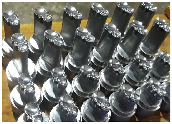
Figure 1.
Typical profiled external cylindrical punches used in pharmaceutical tablet compression.
However, the above studies were conducted under conventional grinding conditions without the assistance of ultrasonic vibration. Although ultrasonic vibration-assisted grinding has been shown to significantly improve surface quality and machining efficiency in various grinding applications, its integration with CBN grinding of profiled external cylindrical surfaces on CNC milling machines has not yet been reported. In particular, systematic investigations addressing the trade-off between SR and MRR under ultrasonic vibration assistance remain absent for this type of functional surface. Therefore, a clear research gap exists in the application of ultrasonic vibration-assisted CBN grinding for profiled external cylindrical surfaces on CNC milling platforms.
To address this research gap, the present study investigates ultrasonic vibration-assisted CBN grinding of external cylindrical surfaces on a CNC milling machine through an integrated experimental and optimization framework. An ultrasonic horn–fixture system is designed and experimentally validated to enable stable transmission of ultrasonic vibration to the workpiece during grinding. The combined influence of ultrasonic vibration amplitude and grinding parameters is systematically analyzed using a Box–Behnken experimental design. Furthermore, Gaussian Process Regression (GPR) surrogate models are integrated with the NSGA-II algorithm to perform multi-objective optimization of Ra and MRR. The resulting Pareto front, convergence behavior, and knee-point solution are analyzed to provide practical decision support for selecting grinding parameters.
Through the integration of ultrasonic-assisted grinding experimentation with surrogate-assisted evolutionary optimization, this study provides new insights into the trade-off between surface quality and productivity in CBN grinding of hardened tool steels, thereby contributing to the development of more efficient grinding strategies for industrial punch-type components.
2. Design of the Ultrasonic Horn System
2.1. Design Concept and Vibration Transmission Strategy
In UVAG systems, ultrasonic energy can be introduced either by exciting the grinding tool (or grinding wheel) or by transmitting vibration directly to the workpiece. Both configurations generate relative ultrasonic motion between abrasive grains and the machined surface; however, their structural complexity and practical applicability differ significantly.
For external cylindrical CBN grinding performed on a CNC milling machine (M-V50C, Mitsubishi, Japan), transmitting ultrasonic vibration to the workpiece was selected as the most appropriate strategy. In contrast to wheel-excited ultrasonic systems, which require a specially designed ultrasonic spindle, power transmission to rotating transducers, dynamic balancing of the spindle–wheel–horn assembly, and substantial structural modifications, the workpiece-excited configuration allows the grinding wheel and spindle to remain in their conventional form. The ultrasonic horn and transducer are integrated into a stationary grinding fixture mounted on the machine table, significantly simplifying system design and reducing implementation cost.
From a kinematic perspective, the effectiveness of UVAG originates from the relative ultrasonic oscillation between the abrasive grains and the workpiece surface. Therefore, transferring vibration to the workpiece does not alter the fundamental material removal mechanism of CBN grinding. Instead, the combined motion of wheel rotation, feed motion, and ultrasonic vibration produces a micro-intermittent cutting action, which is known to reduce grinding forces and improve surface quality. This configuration is particularly suitable for retrofitting existing CNC milling machines for ultrasonic-assisted grinding applications.
2.2. Selection of Horn Geometry and Material
The geometry of an ultrasonic horn governs vibration amplification, stress distribution, and operational stability. Previous studies have reported various standard ultrasonic horn (SUH) profiles, including cylindrical, stepped, conical, exponential, catenoidal, Gaussian, and Bezier-type horns, each exhibiting different trade-offs between vibration amplitude and stress concentration when excited in the fundamental longitudinal mode [26]. Stepped horns generally provide the highest vibration amplitude due to abrupt cross-sectional reduction, whereas smooth-profile horns such as conical, exponential, Gaussian, catenoidal, and Bezier designs offer lower stress levels and improved fatigue life at the expense of reduced amplification [26].
For external cylindrical CBN grinding on a CNC milling machine, high structural stiffness, ease of fabrication, and reliable resonance tuning are critical requirements. Considering these constraints, a stepped cylindrical horn was selected in this study. The chosen design consists of two coaxial cylindrical sections, with a larger-diameter segment near the transducer to ensure rigidity and secure mounting, and a smaller-diameter output segment to amplify vibration amplitude. Compared with smooth-profile horns, this configuration provides a practical balance between vibration amplification capability and structural robustness, while maintaining simple geometry and manufacturability.
The horn material was 90CrSi tool steel, selected for its high stiffness, good fatigue resistance, and suitability for repeated ultrasonic excitation under grinding loads. The material properties used in the design and analysis were Young’s modulus GPa, density kg/m3, and Poisson’s ratio . The high elastic modulus of 90CrSi facilitates efficient longitudinal wave propagation and stable resonance at the operating frequency, making it a suitable material for the ultrasonic horn employed in this study.
2.3. Selection of Ultrasonic Operating Frequency
The operating frequency is a key parameter in ultrasonic vibration-assisted machining, as it governs the dynamic response of the horn–transducer system, achievable vibration amplitude, and process stability. According to the comprehensive review by Brehl and Dow [27], vibration-assisted machining systems reported in the literature operate over a wide frequency range—from a few hertz to approximately 40 kHz—depending on the actuation principle and application. However, the majority of resonant ultrasonic machining systems are designed to operate at discrete frequencies of approximately 20 kHz or 40 kHz, which are readily achievable using commercial ultrasonic generators and piezoelectric transducers.
Among these options, an operating frequency of about 20 kHz has been most widely adopted in practical ultrasonic-assisted cutting and grinding applications. As summarized by Brehl and Dow [27], most one-dimensional resonant ultrasonic systems operate near 20 kHz with vibration amplitudes typically ranging from 3 to 20 μm. This frequency range provides a favorable compromise between vibration amplitude, system stability, and structural stiffness, while avoiding excessive dynamic loading and acoustic noise. In addition, operating at ultrasonic frequencies well above the natural frequencies of conventional machine tool structures minimizes unwanted coupling with machine vibrations, thereby improving process stability and surface quality.
From a design perspective, selecting 20 kHz also leads to a practical horn length corresponding to half-wavelength resonance, which is well suited for integration into compact horn–fixture assemblies on CNC milling machines. Higher frequencies, such as 40 kHz, generally require shorter horns and deliver smaller vibration amplitudes, whereas lower frequencies may compromise the intermittent cutting effect that underpins the benefits of ultrasonic vibration-assisted machining [27].
Based on these considerations and the widespread industrial adoption reported in the literature, an operating frequency of 20 kHz was selected for the ultrasonic horn system in this study. This choice ensures compatibility with standard ultrasonic equipment, enables sufficient vibration amplitude for effective ultrasonic-assisted CBN grinding, and provides stable operation under the constraints of a CNC milling-based grinding setup.
2.4. Theoretical Design of the Stepped Ultrasonic Horn
The ultrasonic horn employed in this study was designed to operate in the fundamental longitudinal vibration mode at an operating frequency of 20 kHz. As illustrated in Figure 1, the horn–fixture assembly consists of a stepped cylindrical structure made of 90CrSi tool steel, in which the transducer is attached at a longitudinal vibration node (zero displacement), while the workpiece is clamped at the antinodal region to maximize vibration amplitude at the output end.
For longitudinal resonance, the total effective length of the horn must satisfy the half-wavelength condition, which can be expressed as
where is the total horn length, is the wavelength of the longitudinal ultrasonic wave, is the longitudinal wave velocity in the horn material, and is the ultrasonic operating frequency.
The horn was fabricated from 90CrSi tool steel. The longitudinal wave velocity in the horn material was calculated using the classical elastic wave relation [28]:
where is Young’s modulus and is the material density. Substituting the material properties of 90CrSi steel ( Pa and kg/m3) yields
At the selected operating frequency of Hz, the corresponding wavelength is
Accordingly, the theoretical half-wavelength resonance length of the horn is
The stepped horn geometry was divided into three coaxial sections with lengths , , and (see Figure 2), such that
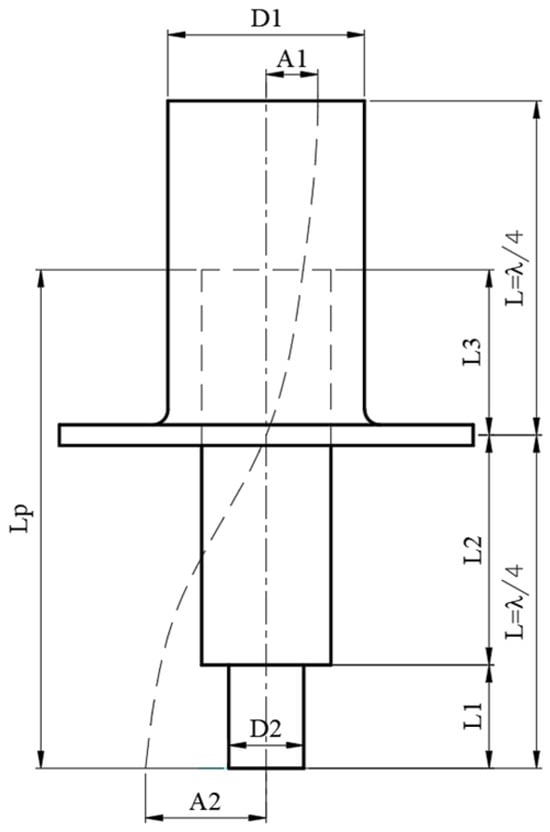
Figure 2.
Diagram for calculating workpiece length.
Based on the actual workpiece geometry and fixture requirements, the small-diameter output section was designed with mm, while the large-diameter rear section was assigned mm. Substituting these values into Equation (6) gives
The value of mm represents the theoretical length of the intermediate horn section required to achieve longitudinal resonance at 20 kHz. It should be noted that this analytical calculation provides an initial estimate only. In practice, the horn length corresponding to maximum vibration amplitude may deviate slightly from the theoretical value due to geometric discontinuities, boundary conditions, and coupling effects with the transducer and fixture. Therefore, the calculated length serves as a guideline for design, and fine adjustment of was subsequently performed through experimental validation to determine the optimal configuration.
2.5. Fabrication and Assembly of the Horn–Fixture System
Based on the theoretical design, the stepped ultrasonic horn was fabricated and assembled with a commercial ultrasonic transducer to form a complete horn–fixture system. The horn was rigidly fixed to the grinding fixture at the vibration node to suppress unwanted energy dissipation. The workpiece was clamped at the antinodal region, where vibration amplitude reaches its maximum.
The entire horn-fixture assembly was mounted on the machine table of the CNC milling machine, while the CBN grinding wheel remained mounted on the conventional rotating spindle. This arrangement ensures high structural rigidity, stable vibration transmission, and compatibility with standard grinding wheels. Moreover, the modular design allows easy replacement of workpieces with different lengths without modifying the ultrasonic source or spindle system.
2.6. Experimental Verification of Resonance and Vibration Amplitude
After completing the theoretical design of the stepped ultrasonic horn, experimental verification was conducted to evaluate the resonance condition and vibration amplitude of the horn–fixture system. The primary objective of this experimental stage was to confirm the effectiveness of the designed horn in amplifying ultrasonic vibration and to identify the configuration corresponding to maximum vibration amplitude at the workpiece end.
2.6.1. Fabrication and Experimental Setup
The designed stepped ultrasonic horn was fabricated from 90CrSi tool steel and integrated with a commercial ultrasonic transducer (model RPS-T5020-4Z -Hangzhou Lanben, Hangzhou, China) with a nominal resonance frequency of 20 kHz. The horn–transducer assembly was mounted on a dedicated grinding fixture designed for installation on the table of a CNC milling machine. Figure 3a,b illustrate the three-dimensional model of the horn–fixture system and the actual experimental setup mounted on the CNC machine, respectively.
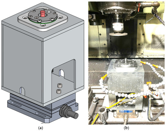
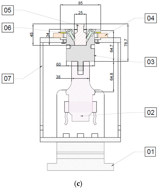
Figure 3.
Ultrasonic horn–fixture system integrated with the CNC milling machine: (a) 3D design model; (b) experimental setup on the machine table; (c) cross-sectional view of the ultrasonic-assisted grinding workstation showing the arrangement of the main components: (01) Kistler force sensor, (02) ultrasonic vibration head, (03) transducer, (04) transducer mounting flange, (05) grinding specimen, (06) plastic pad, and (07) supporting frame.
An ultrasonic generator (MGI WG-3000, MPI Ultrasonics, Le Locle, Switzerland) with a maximum output power of 3000 W was used to excite the transducer at 20 kHz. The vibration amplitude at the output end of the horn was measured using a non-contact optical displacement sensor (Philtec D170-BEG1H, Annapolis, MD, USA), which provides a measurement resolution of 0.173 µm. The measurement setup and optical sensor are shown schematically in Figure 4.
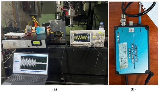
Figure 4.
Measurement of ultrasonic vibration amplitude using a non-contact optical displacement sensor: (a) measurement setup; (b) optical sensor (Philtec D170-BEG1H—Annapolis, MD, USA).
2.6.2. Measurement Procedure
To investigate the influence of horn length on vibration amplitude and to identify the resonance condition, experiments were carried out with different effective lengths of the horn–workpiece assembly. The ultrasonic system was operated at a fixed excitation frequency of 20 kHz, while the vibration amplitude at the horn output end was recorded for each configuration.
For each tested length, the vibration amplitude was measured after the system reached a steady oscillation state. The measurements were repeated to ensure repeatability, and the average amplitude value was used for subsequent analysis.
2.6.3. Experimental Results and Discussion
The measured vibration amplitudes A corresponding to different effective horn lengths L are summarized in Table 1. The results reveal a clear dependence of vibration amplitude on horn length, indicating the presence of a resonance condition within the investigated range.

Table 1.
Measured ultrasonic vibration amplitude at different horn lengths.
Figure 5 presents the relationship between horn length and vibration amplitude. As shown, the vibration amplitude increases gradually with increasing horn length and reaches a maximum value of 26.12 µm at an effective horn length of 98 mm. Beyond this point, further increases in length lead to a reduction in vibration amplitude, indicating detuning from the resonance condition.
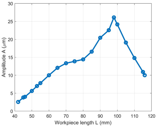
Figure 5.
Relationship between effective horn length and ultrasonic vibration amplitude at 20 kHz.
The experimentally identified optimal length of 98 mm is close to, but not exactly equal to, the theoretical value obtained from the half-wavelength resonance calculation. This discrepancy can be attributed to practical factors such as geometric discontinuities in the stepped horn, boundary conditions introduced by the fixture and clamping mechanism, and coupling effects between the horn and the transducer. Nevertheless, the experimental results confirm that the designed horn provides a substantial amplification of vibration amplitude, increasing the amplitude from approximately 10 µm at the transducer output to more than 26 µm at the horn output, corresponding to an amplification factor of approximately 2.6.
These results demonstrate that the proposed stepped ultrasonic horn and fixture system can effectively achieve resonance and deliver sufficiently large vibration amplitudes for ultrasonic vibration-assisted CBN grinding. The experimentally determined optimal configuration was therefore adopted in subsequent grinding experiments and multi-objective optimization analyses.
3. Experimental Work
3.1. Grinding System and Ultrasonic Assistance
All experiments were carried out on a CNC milling machine retrofitted with the ultrasonic horn–fixture system described in Section 2. The ultrasonic vibration was transmitted directly to the workpiece through the stepped horn, while the CBN grinding wheel rotated conventionally on the machine spindle. The ultrasonic system operated at a fixed frequency of 20 kHz, and the vibration amplitude was controlled by adjusting the output power of the ultrasonic generator.
During external cylindrical grinding, careful alignment between the grinding wheel axis, horn axis, and workpiece axis was ensured to maintain coaxiality and stable contact conditions. This configuration allowed independent control of conventional grinding parameters and ultrasonic vibration conditions without modifying the spindle system.
3.2. Process Parameters and Experiment Design
The ranges of conventional grinding parameters were selected based on previous studies on CBN grinding of tool steels conducted on CNC milling platforms [29]. According to these studies, stable grinding conditions with acceptable surface quality and productivity can be achieved within the following parameter ranges: Grinding wheel rotational speed: rpm; Feed rate of the grinding wheel: mm/min; Radial depth of cut: mm.
In contrast to the above parameters, the ultrasonic vibration amplitude depends strongly on the resonance characteristics of the horn–fixture–workpiece system and therefore cannot be directly adopted from the literature. For this reason, exploratory experiments were performed to determine an appropriate amplitude range for ultrasonic vibration-assisted CBN grinding.
In the exploratory tests, the grinding parameters were fixed at rpm, mm/min, and , while the ultrasonic vibration amplitude was varied over a wide range. The corresponding MRR was measured for each amplitude level. The experimental results are summarized in Table 2, and the relationship between vibration amplitude and MRR is illustrated in Figure 5.
Table 2.
Experimental results of the exploratory tests showing the effect of ultrasonic vibration amplitude on MRR.
As shown in Table 2 and Figure 6, the MRR increases rapidly with increasing vibration amplitude up to approximately , where the maximum MRR is observed. Beyond this range, further increases in amplitude result in a reduction in MRR, which can be attributed to excessive intermittent separation between the grinding wheel and the workpiece, reducing effective abrasive engagement. Based on these observations, the ultrasonic vibration amplitude range was selected as A = 4 to 10 µm for subsequent experiments and multi-objective optimization.
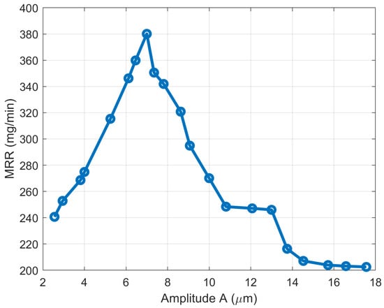
Figure 6.
Relationship between ultrasonic vibration amplitude and MRR under constant grinding conditions.
Supplementary Description of Experimental Design:
To systematically investigate the combined effects of ultrasonic vibration and grinding parameters on SR and MRR, the experiments were designed using a Box–Behnken Design (BBD). The BBD is an efficient response surface methodology that enables the development of quadratic models with a reduced number of experimental runs while avoiding extreme combinations of process parameters. This feature is particularly advantageous for grinding experiments, where excessive parameter levels may lead to unstable cutting conditions, excessive wheel wear, or surface damage.
In the present study, four control factors were considered: ultrasonic vibration amplitude (), grinding wheel rotational speed (), feed rate (), and radial depth of cut (). Each factor was investigated at three levels, coded as −1, 0, and +1, corresponding to low, medium, and high values, respectively. The parameter ranges were selected based on preliminary experiments and relevant literature, ensuring both process stability and sufficient variability for modeling. The experimental matrix generated by the BBD, together with the measured responses of and MRR, is presented in Table 3.
Table 3.
Input factors and levels used in the Box–Behnken experimental design.
3.3. Measurement of Surface Roughness
The SR was evaluated using the arithmetic mean roughness parameter , which is commonly employed to characterize ground surface quality. Measurements were performed using a SURFTEST SJ-310 SR tester (Mitutoyo Corp., Kawasaki, Japan). For each experimental condition, SR was measured at multiple positions along the ground cylindrical surface, and the average value was reported to minimize the influence of local surface irregularities and measurement uncertainty.
3.4. Determination of Material Removal Rate
The MRR was determined using the mass-loss method. The workpiece mass before and after grinding was measured using an electronic balance (WT3003NE) with high measurement resolution. The MRR was calculated according to
where and are the workpiece masses before and after grinding (kg), respectively, is the material density (kg/m3), and is the grinding time (min). This approach provides reliable and repeatable quantification of material removal in grinding experiments.
3.5. Experimental Procedure and Data Acquisition
The experimental procedure and data acquisition process employed to generate the dataset for subsequent multi-objective optimization are described in this section. The overall experimental setup is illustrated in Figure 7. All grinding experiments were carried out on an M-V50C CNC milling machine (Mitsubishi) equipped with the ultrasonic horn–fixture system described in Section 2.
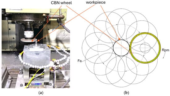
Figure 7.
Experimental setup: (a) experimental setup on the CNC milling machine; (b) schematic illustration of grinding wheel motion and workpiece engagement.
The grinding wheel used for material removal was a cubic boron nitride (CBN) wheel manufactured by Norton (Winter, Saint-Gobain Abrasives, Würzburg, BY, Germany), with the designation B91 KSSRY A V240-D-1K1A1-125-6-7. The abrasive consisted of CBN grains with a medium grit size of B91 (approximately 91 µm), selected to provide a balanced compromise between surface finish and material removal capability under ultrasonic vibration-assisted grinding conditions. The wheel utilized a resin bond system (KSSRY), which is suitable for wet grinding and offers favorable self-sharpening behavior, thermal stability, and vibration damping characteristics. The abrasive concentration was V240, ensuring sufficient grain density to sustain stable grinding performance under hard machining conditions.
The wheel geometry corresponded to the standard 1K1A1 cylindrical surface grinding type, with an outer diameter of 125 mm, a grinding rim thickness of 6 mm, and a bore diameter of 7 mm. The wheel body (denoted as Body A) was fabricated from steel to provide adequate structural rigidity and dynamic stability during high-speed rotation and ultrasonic vibration interaction. The combination of medium grit size, resin bond, and controlled abrasive concentration was intentionally selected to achieve stable abrasive engagement while limiting excessive surface damage during ultrasonic vibration-assisted external cylindrical grinding.
The experimental workpieces were manufactured from 90CrSi alloy tool steel, a medium-alloy high-carbon steel widely used for punches, dies, and wear-resistant mechanical components. This steel contains approximately 0.9% carbon and alloying elements such as chromium (Cr) and silicon (Si), which enhance hardenability and improve wear resistance under high-contact stress conditions.
Prior to grinding, the specimens were subjected to heat treatment consisting of oil quenching at approximately 840 °C followed by low-temperature tempering at 200 °C. After heat treatment, the material achieved a hardness of approximately 58–60 HRC, representing typical industrial hard-grinding conditions for tool steel components.
The geometry of the workpiece is illustrated in Figure 8. The specimen consisted of a stepped cylindrical profile with a maximum base diameter of 25 mm and an upper cylindrical section of 14.5 mm in diameter. The grinding operation focused on the external cylindrical section, where the diameter was reduced from Ø14.5 mm to Ø14 mm under ultrasonic vibration-assisted CBN grinding.
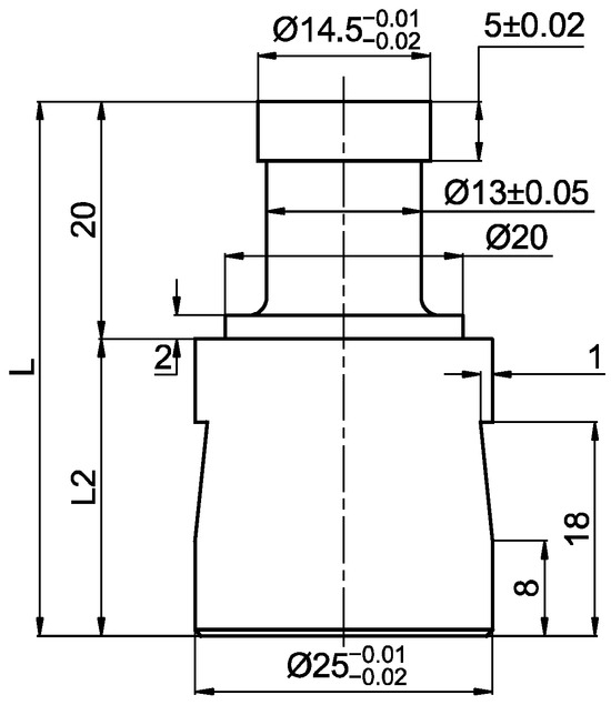
Figure 8.
Geometry and main dimensions of the hardened 90CrSi workpiece used in the grinding experiments (dimensions in mm).
All grinding experiments were performed under wet grinding conditions using a flood cooling method. The coolant employed was Caltex Aquatex 3180 (Chevron Corp., Singapore), a water-miscible soluble oil formulated from specially refined base oils, emulsifying agents, binding additives, and active components designed to produce a stable emulsion system. This coolant is widely used in cutting and grinding operations due to its effective cooling capacity, lubrication performance, and ability to reduce wheel loading and thermal damage.
The coolant was supplied continuously to the grinding zone using the machine’s built-in flood delivery system. The spraying pressure corresponded to the standard flood pressure of the CNC milling machine and remained constant throughout all experiments. The nozzle was positioned to directly target the wheel-workpiece contact area to ensure efficient heat dissipation and chip evacuation.
The cooling and lubrication conditions were kept constant for all experimental runs in order to eliminate their influence as uncontrolled variables and ensure that only the selected process parameters (A, n, ae, vf) affected the grinding responses.
The workpieces were ground following the machining scheme shown in Figure 7b. During the grinding process, the grinding wheel rotated about its own axis while simultaneously moving along a programmed orbital path defined in the CNC machining program, enabling controlled external cylindrical grinding on the milling platform.
For each experimental run, the surface quality was evaluated by measuring the arithmetic mean SR using the procedure described in Section 3.3. Subsequently, the MRR was calculated based on the mass-loss method using Equation (8), which accounts for the difference between the workpiece mass before and after grinding and the corresponding grinding time.
The grinding time for each workpiece was recorded directly from the CNC milling machine during machining. For the 29 experimental runs in the Box–Behnken design, the grinding time ranged from approximately 1.1 to 2.04 min, depending on the selected grinding parameters. No noticeable overheating of the ultrasonic horn was observed during the experiments, as the system operated under stable resonance conditions and continuous flood cooling effectively dissipated the generated heat.
The experimental design, including the combinations of process parameters and the resulting output responses (Ra and MRR), is summarized in Table 4. This experimentally obtained dataset constitutes the basis for developing surrogate models and performing the multi-objective optimization using the NSGA-II algorithm. By simultaneously considering SR and MRR as conflicting objectives, the acquired data enable a systematic analysis of the trade-off behavior between surface quality and machining efficiency.
Table 4.
Experimental design matrix and output responses.
3.6. Repeatability and Stability Analysis
To ensure the reliability and repeatability of the experimental results, each grinding condition was repeated three times under identical process parameters. For each repetition, the SR was measured at three different locations along the ground cylindrical surface, and the average value was taken as the representative Ra for that trial. The Ra and MRR values reported in Table 4 correspond to the mean values of the three repeated grinding experiments.
To further evaluate the stability of the experimental system, the central point of the Box–Behnken design (A = 7 µm, n = 5000 rpm, ae = 0.025 mm, vf = 3000 mm/min) was repeated five times (Runs 6, 11, 19, 20, and 27). Statistical dispersion was assessed using the standard deviation (SD) and coefficient of variation (CV).
For the MRR, the repeated central runs yielded a mean value of 418.22 mg/min with an SD of 3.12 mg/min and a CV of 0.75%, indicating excellent repeatability and highly stable material removal performance.
For SR, the corresponding mean value was 0.372 µm with an SD of 0.0289 µm and a CV of 7.76%. Although the relative dispersion of Ra is higher than that of MRR, the absolute deviation remains small. This behavior is consistent with the intrinsic sensitivity of SR to localized abrasive–workpiece interactions and micro-scale surface formation mechanisms in ultrasonic vibration-assisted grinding. Because Ra is governed by stochastic grain engagement and local surface texture variations, it is inherently more sensitive to small process fluctuations and measurement positioning than global metrics such as MRR.
Overall, the low dispersion of MRR and the mechanism-consistent variability of Ra confirm the stability and reliability of the experimental system, providing a sound basis for subsequent surrogate modeling and multi-objective optimization.
4. Multi-Objective Optimization Using NSGA-II
4.1. Problem Formulation and Optimization Framework
In ultrasonic vibration-assisted CBN grinding, and MRR represent two conflicting performance objectives. A reduction in surface roughness generally requires conservative cutting conditions, whereas an increase in MRR is often accompanied by surface degradation. Therefore, the optimization problem was formulated as a bi-objective problem, aiming to simultaneously minimize and maximize MRR:
where is the vector of decision variables corresponding to ultrasonic vibration amplitude, grinding wheel rotational speed, feed rate, and radial depth of cut, respectively. The decision variables were constrained within the experimentally determined ranges described in Section 3.
To efficiently explore the multi-objective solution space while reducing computational cost, surrogate models based on Gaussian Process Regression (GPR) were employed to approximate the nonlinear relationships between process parameters and responses. These surrogate models were subsequently integrated with the Non-dominated Sorting Genetic Algorithm II (NSGA-II) to generate Pareto-optimal solutions.
4.2. Surrogate Model Validation
The predictive accuracy of the GPR models for both objectives was evaluated using training and cross-validation metrics. The comparison between predicted and experimentally measured values is illustrated in Figure 9. As shown, the predicted values of both and MRR exhibit good agreement with the experimental data.
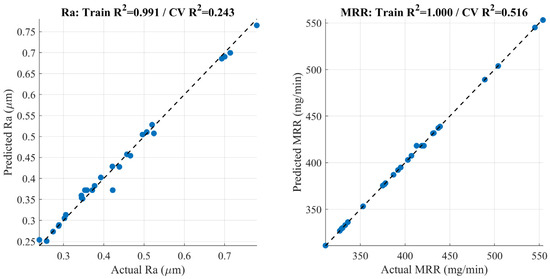
Figure 9.
Experimental GPR validation (Predicted vs. Actual).
For SR, the GPR model achieved a training coefficient of determination of , indicating excellent fitting capability, while the cross-validation reflects the inherent variability of SR measurements in grinding processes. For MRR, an almost perfect training performance () and a higher cross-validation accuracy were obtained, confirming the robustness of the surrogate model for productivity-related prediction. These results demonstrate that the developed GPR models are sufficiently accurate to support multi-objective optimization.
4.3. NSGA-II Configuration and Convergence Analysis
The NSGA-II algorithm was applied using a population-based evolutionary framework to approximate the Pareto front of the formulated optimization problem. The convergence behavior of the optimization process was assessed using the hypervolume (HV) indicator, which reflects both convergence and diversity of the obtained Pareto solutions.
The evolution of the hypervolume value with generation number is shown in Figure 10. A rapid increase in hypervolume is observed during the early generations, indicating fast convergence toward the Pareto-optimal region. After approximately 40–50 generations, the hypervolume curve gradually stabilizes, suggesting that the algorithm has reached a near-converged state. Beyond this point, further generations mainly refine the distribution of solutions along the Pareto front rather than significantly improving solution quality. This behavior confirms the effectiveness and stability of the NSGA-II algorithm when coupled with GPR surrogate models for the present grinding optimization problem.
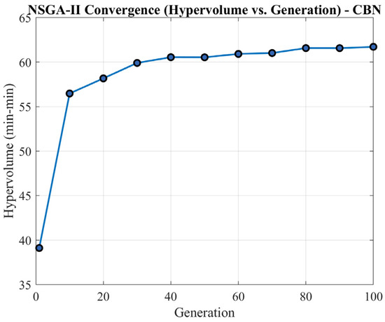
Figure 10.
NSGA-II convergence via hypervolume.
4.4. Evolution of the Pareto Front
To further illustrate the optimization dynamics, snapshots of the Pareto front at different generations are presented in Figure 11. In the initial generation, the solutions are widely scattered and far from the optimal trade-off region. As the algorithm progresses, the Pareto front gradually moves toward higher MRR and lower SR, while maintaining good diversity.
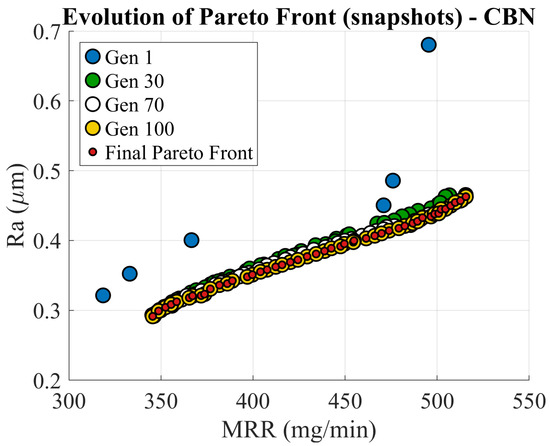
Figure 11.
Pareto front evolution (snapshots).
By the final generation, the Pareto front becomes smooth and well distributed, indicating that NSGA-II successfully captures the trade-off relationship between surface quality and material removal efficiency. The progressive evolution of the Pareto front demonstrates the capability of the algorithm to balance exploration and exploitation during the optimization process.
4.5. Final Pareto Front and Trade-Off Analysis
The final Pareto front obtained using the NSGA-II–GPR framework is shown in Figure 10. The results clearly reveal a monotonic trade-off between SR and MRR: higher MRR values are associated with increased SR, whereas lower values require a reduction in MRR.
This trade-off behavior is consistent with the physical characteristics of grinding processes and highlights the necessity of multi-objective optimization rather than single-objective tuning. The smooth and continuous shape of the Pareto front further indicates that the surrogate-assisted optimization framework effectively captures the underlying process behavior.
This trade-off can be explained by the physical mechanism of abrasive–workpiece interaction during grinding. When the grinding parameters promote higher MRR, the engagement between abrasive grains and the workpiece becomes more aggressive, resulting in deeper penetration of abrasive grains into the surface. The repeated contact and impact of abrasive grains may induce localized plastic deformation and micro-fractures on the workpiece surface. These micro-scale damage mechanisms facilitate higher material removal but simultaneously lead to a deterioration of surface quality, which manifests as an increase in SR. Consequently, higher MRR levels are generally associated with larger Ra values in ultrasonic vibration-assisted grinding.
4.6. Knee Point Identification and Engineering Interpretation
For practical implementation of the multi-objective optimization results, it is necessary to select a representative solution from the set of Pareto-optimal solutions. In this study, a knee point was identified on the final Pareto front, as highlighted in Figure 12. The knee point corresponds to a region where a marginal improvement in one objective would result in a disproportionate deterioration in the other, thereby representing a balanced trade-off between surface quality and material removal efficiency.
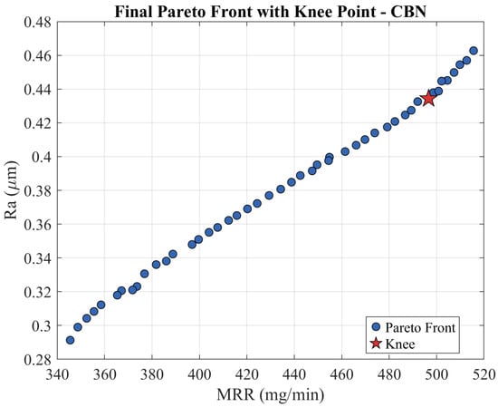
Figure 12.
Pareto front and knee point.
As observed in Figure 12, the Pareto front exhibits a smooth and monotonic trade-off between SR and MRR, indicating physically consistent optimization behavior. The knee region is located at an intermediate position along the Pareto front, where both objectives simultaneously attain competitive values without extreme sacrifice. This characteristic makes the knee point particularly suitable for engineering decision-making in grinding applications that require a compromise between productivity and surface integrity.
Based on the knee-point solution, the optimal grinding parameters were identified as follows: Ultrasonic vibration amplitude: ; Grinding wheel rotational speed: rpm; Feed rate of the grinding wheel: mm/min; and radial depth of cut: .
Under these operating conditions, a balanced grinding performance was achieved with a SR of approximately and a MRR of about 490–500 mg/min.
From an engineering perspective, the knee-point solution reflects the optimal utilization of ultrasonic vibration-assisted grinding. At this operating point, the vibration amplitude generated by the designed ultrasonic horn is sufficient to promote intermittent abrasive–workpiece contact, reduce effective grinding forces, and enhance material removal. At the same time, abrasive engagement remains stable enough to prevent excessive surface damage, thereby maintaining acceptable SR. Increasing the vibration amplitude or aggressive grinding parameters beyond this point leads to diminishing returns in MRR and accelerated degradation of surface quality, as evidenced by the shape of the Pareto front.
Therefore, the knee-point solution provides a physically meaningful and application-oriented optimal grinding regime for ultrasonic vibration-assisted external cylindrical CBN grinding on a CNC milling platform. This solution serves as a practical guideline for parameter selection in industrial applications where both productivity and surface quality are critical.
5. Discussion
The multi-objective optimization results demonstrate that the performance of ultrasonic vibration-assisted CBN grinding is strongly governed by the interaction between the ultrasonic horn design and the grinding process parameters. The stepped ultrasonic horn developed in this study enables stable vibration transmission and provides a controllable amplitude range, which directly shapes the structure of the Pareto front obtained from NSGA-II optimization.
The smooth and continuous Pareto front indicates that the horn–fixture–workpiece system operates under stable resonance conditions, avoiding irregular or discontinuous trade-off regions that may arise from unstable ultrasonic excitation. This stability allows the optimization algorithm to capture a physically meaningful trade-off between SR and MRR. At lower vibration amplitudes, grinding behavior is dominated by conventional abrasive interaction, resulting in limited productivity but improved surface finish. As the vibration amplitude increases, intermittent abrasive–workpiece contact intensifies, reducing effective grinding forces and enhancing material removal efficiency.
However, the Pareto front also reveals that excessive vibration amplitude does not lead to continuous performance improvement. Beyond a certain amplitude range, increased separation between the grinding wheel and the workpiece reduces effective abrasive engagement, which limits further gains in MRR and may deteriorate surface quality. This behavior is consistent with the experimentally observed amplitude–MRR relationship and confirms the existence of a practical operating limit imposed by the horn-induced vibration characteristics.
The knee point identified on the Pareto front provides a clear engineering interpretation of this coupled behavior. The knee-point solution represents operating conditions under which the ultrasonic horn delivers sufficient vibration energy to enhance material removal while maintaining controlled abrasive engagement and acceptable SR. From an application standpoint, this solution corresponds to the most efficient use of the horn’s amplification capability without entering regimes of diminishing returns or unstable grinding.
Overall, the close correspondence between horn design characteristics, experimentally validated vibration response, and Pareto front structure highlights the importance of integrating ultrasonic system design with multi-objective process optimization. The results confirm that optimal grinding performance emerges from the coupled design of the ultrasonic horn and process parameters, rather than from isolated parameter tuning.
6. Conclusions
This study presented an integrated experimental and multi-objective optimization framework for ultrasonic vibration-assisted external cylindrical CBN grinding performed on a CNC milling machine. A stepped ultrasonic horn was designed, theoretically analyzed, and experimentally validated to ensure stable resonance and effective vibration amplification at the workpiece. The horn–fixture system enabled controllable ultrasonic vibration amplitudes suitable for grinding hardened tool steel under practical machining conditions.
The experimental dataset was generated using a Box–Behnken Design, which enabled efficient modeling of the combined effects of grinding parameters and ultrasonic vibration while avoiding extreme operating conditions. Based on the experimental results, surrogate models using Gaussian Process Regression were developed to accurately describe the nonlinear relationships between grinding parameters and performance responses. These models were successfully coupled with the NSGA-II algorithm to simultaneously minimize SR and maximize MRR.
The obtained Pareto front revealed a clear and physically consistent trade-off between surface quality and productivity. A knee-point solution was identified as a representative optimal operating regime, providing a balanced compromise between SR and material removal efficiency. The corresponding grinding parameters demonstrate that ultrasonic vibration can significantly enhance grinding performance when applied within an appropriate amplitude range, whereas excessive vibration leads to diminishing returns due to reduced abrasive engagement.
Overall, the results highlight that optimal grinding performance arises from the coupled design of the ultrasonic horn system and the grinding process parameters, rather than from isolated parameter tuning. The proposed framework provides practical guidelines for parameter selection and offers a reliable decision-support tool for implementing ultrasonic vibration-assisted CBN grinding on CNC milling platforms. Future work may extend this approach by incorporating additional objectives, such as grinding force or wheel wear, to support more comprehensive industrial optimization requirements.
Author Contributions
Conceptualization was proposed by T.-T.H. and N.-P.V., and all authors contributed to the discussion and refinement of the research idea. T.-T.H. conducted the experimental work and analyzed the experimental data with the support of A.-T.L., T.-T.H. and N.-P.V. collaboratively prepared and revised the manuscript. All authors have read and agreed to the published version of the manuscript.
Funding
This research received no external funding.
Institutional Review Board Statement
Not applicable.
Informed Consent Statement
Not applicable.
Data Availability Statement
The original contributions presented in this study are included in the article. Further inquiries can be directed to the corresponding author.
Acknowledgments
This work was supported by Thai Nguyen University of Technology.
Conflicts of Interest
The authors declare no conflicts of interest.
Abbreviations
The following abbreviations are used in this manuscript:
| CBN | cubic boron nitride |
| Ra | surface roughness |
| MRR | Material removal rate (g/h) |
| NSGA-II | non-dominated sorting genetic algorithm II |
| UVAG | ultrasonic vibration-assisted grinding |
| CNC | computer numerical control |
References
- Hu, L.; Pueh, L.H.; Wang, Z.; Wang, Y. Surface performance control and evaluation of precision bearing raceway with wireless sensing CBN grinding wheel. Wear 2025, 568, 205966. [Google Scholar] [CrossRef]
- Breuer, P.; Künkel, T.; Werner, J.; Müller, U.; Bergs, T.; Weirich, T.E. Investigation of the structural stability of polycrystalline cBN under near-industrial grinding process conditions. Int. J. Refract. Met. Hard Mater. 2024, 122, 106720. [Google Scholar] [CrossRef]
- Benkai, L.; Ding, W.; Zhu, Y.; Li, C.; Zhang, Y.; Yang, M.; Ma, X.; Liu, M.; Cui, X. Design and grindability assessment with cup shaped electroplated CBN wheel grinding turbine disc slots of powder metallurgy superalloy FGH96. Chin. J. Aeronaut. 2024, 37, 521–534. [Google Scholar]
- Zhang, C.; Qu, S.; Xi, W.; Liang, Y.; Zhao, J.; Yu, T. Preparation of a novel vitrified bond CBN grinding wheel and study on the grinding performance. Ceram. Int. 2022, 48, 15565–15575. [Google Scholar] [CrossRef]
- Zhao, B.; Ding, W.; Xiao, G.; Zhao, J.; Li, Z. Self-sharpening property of porous metal-bonded aggregated cBN wheels during the grinding of Ti–6Al–4V alloys. Ceram. Int. 2022, 48, 1715–1722. [Google Scholar] [CrossRef]
- Zhao, B.; Ding, W.; Xiao, G.; Zhao, J.; Li, Z. Effects of open pores on grinding performance of porous metal-bonded aggregated cBN wheels during grinding Ti–6Al–4V alloys. Ceram. Int. 2021, 47, 31311–31318. [Google Scholar] [CrossRef]
- Kirsch, B. Quantitative analysis of the wear of electroplated cBN grinding wheels when grinding AISI 4140. Wear 2025, 578, 206227. [Google Scholar] [CrossRef]
- Zhao, B.; Ding, W.; Xiao, G.; Cai, K.; Li, Z.; Pu, C. Micro-fracture behavior of a single-aggregated cBN grain and its relation to material removal in high-speed grinding of Ti–6Al–4V alloys. J. Manuf. Process. 2022, 79, 19–27. [Google Scholar] [CrossRef]
- Jamshidi, H.; Bagherzadeh, A.; Budak, E.; Ghadbeigi, H. A predictive wear model in grinding using single-layer electroplated cBN tools. J. Manuf. Process. 2024, 127, 251–258. [Google Scholar] [CrossRef]
- Bredthauer, M.; Snellings, P.; Mattfeld, P.; Bergs, T. Wear-related topography changes for electroplated cBN grinding wheels and their effect on thermo-mechanical load. Wear 2023, 512, 204543. [Google Scholar] [CrossRef]
- Wang, Z.; Li, J.; Liu, Q.; Chen, L.; Lv, J.; Yu, T.; Zhao, J. No-impact trajectory design and fabrication of surface structured CBN grinding wheel by laser cladding remelting method. Opt. Laser Technol. 2025, 181, 111956. [Google Scholar] [CrossRef]
- Dai, J.; Li, Y.; Xiang, D. The mechanism investigation of ultrasonic roller dressing vitrified bonded CBN grinding wheel. Ceram. Int. 2022, 48, 24421–24430. [Google Scholar] [CrossRef]
- Zhu, P.; Cai, F.; Dong, Z.; Xu, N.; Kang, R.; Han, W.; Zhang, Y. Surface plastic deformation study of directionally solidified nickel-based superalloy machined by ultrasonic vibration grinding. J. Mater. Res. Technol. 2025, 37, 2567–2576. [Google Scholar] [CrossRef]
- Ma, X.; Jiao, F.; Chen, F.; Niu, Y.; Li, C.; Tong, J.; Bie, W. Effects of ultrasonic vibration on the machining mechanism of internal cylindrical ultrasonic-assisted electrochemical hybridized grinding of bearing ring: Experimental study. J. Manuf. Process. 2025, 150, 129–146. [Google Scholar] [CrossRef]
- Dai, C.; Dai, B.; Miao, Q.; Yin, Z.; Chen, J. Experimental and simulation analysis of surface morphology characteristics through multiple methods of ultrasonic vibration-assisted grinding using a single grain. Precis. Eng. 2025, 93, 355–367. [Google Scholar] [CrossRef]
- Zhang, K.; Dai, C.; Yin, Z.; Miao, Q.; Chen, J.; Cheng, Q.; Yang, S. Modeling and prediction on grinding force in ultrasonic assisted elliptical vibration grinding (UAEVG) of SiC ceramics using single diamond grain. J. Manuf. Process. 2024, 131, 2244–2254. [Google Scholar] [CrossRef]
- Zheng, W.; Tang, X.; Qu, D.; Liu, L. Study of ultrasonic vibration-assisted grinding SiCp/Al composites: Surface formation mechanism considering interface failure and process method towards low surface defects. J. Manuf. Process. 2024, 131, 2382–2399. [Google Scholar] [CrossRef]
- Zhou, Y.; Jia, S.; Lu, Y.; Liu, J.; Ma, L.; Li, M.; Li, D.; Yin, G. Study on ultrasonic elliptical vibration-assisted grinding mechanism and surface quality of C/SiC composite material. Diam. Relat. Mater. 2024, 149, 111565. [Google Scholar] [CrossRef]
- Xu, N.; Dong, Z.; Kang, R.; Bao, Y.; Du, H.; Shan, K.; Guo, D.; Wang, Y. Surface microstructure evolution analysis of Inconel 718 during ultrasonic vibration-assisted grinding using FEM. J. Manuf. Process. 2024, 127, 631–644. [Google Scholar] [CrossRef]
- Li, C.; Zhang, F.; Meng, B.; Liu, L.; Rao, X. Material removal mechanism and grinding force modelling of ultrasonic vibration assisted grinding for SiC ceramics. Ceram. Int. 2017, 43, 2981–2993. [Google Scholar] [CrossRef]
- Kuffa, M.; Kuster, F.; Wegener, K. Comparison of lubrication conditions for grinding of mild steel with electroplated cBN wheel. CIRP J. Manuf. Sci. Technol. 2017, 18, 53–59. [Google Scholar] [CrossRef]
- Ji, K.; Zhang, X.; Yang, S.; Shi, L.; Wang, S.; Wu, Y. Surface integrity of quenched steel 1045 machined by CBN grinding wheel and SiC grinding wheel. Int. J. Struct. Integr. 2017, 8, 179–187. [Google Scholar] [CrossRef]
- Chen, H.; Tang, J.; Zhou, W. An experimental study of the effects of ultrasonic vibration on grinding surface roughness of C45 carbon steel. Int. J. Adv. Manuf. Technol. 2013, 68, 2095–2098. [Google Scholar] [CrossRef]
- Vu, N.-P.; Nguyen, Q.T.; Tran, T.H.; Le, H.K.; Nguyen, A.T.; Luu, A.T.; Nguyen, V.T.; Le, X.H. Optimization of grinding parameters for minimum grinding time when grinding tablet punches by CBN wheel on CNC milling machine. Appl. Sci. 2019, 9, 957. [Google Scholar] [CrossRef]
- Danh, B.T.; Van Khoa, V.; Linh, N.H.; Tu, H.X.; Van Tung, N.; Hien, B.T. Multi-criteria decision making in CBN grinding tool steel using TOPSIS method. J. Mil. Sci. Technol. 2023, 87, 94–99. [Google Scholar] [CrossRef]
- Ahmad, S.; Maqbool, A.; Raza, S.F.; Qaiser, A.A.; Khalid, F.A.; Zhang, J. Harmonic excitation response of standard ultrasonic horn designs for machining Nomex honeycomb core composite. J. Kejuruter. 2024, 36, 49–62. [Google Scholar] [CrossRef]
- Brehl, D.E.; Dow, T.A. Review of vibration-assisted machining. Precis. Eng. 2008, 32, 153–172. [Google Scholar] [CrossRef]
- Ensminger, D.; Stulen, F.B. Ultrasonics: Data, Equations and Their Practical Uses; CRC Press: Boca Raton, FL, USA, 2008. [Google Scholar]
- Hien, B.T. Determining Appropriate Grinding Parameters for Square External Cylindrical SKD11 Steel Parts Using CBN Wheels on a CNC Milling Machine. Ph.D. Thesis, Thai Nguyen University of Technology, Thai Nguyen City, Vietnam, 2024. [Google Scholar]


Disclaimer/Publisher’s Note: The statements, opinions and data contained in all publications are solely those of the individual author(s) and contributor(s) and not of MDPI and/or the editor(s). MDPI and/or the editor(s) disclaim responsibility for any injury to people or property resulting from any ideas, methods, instructions or products referred to in the content. |
© 2026 by the authors. Licensee MDPI, Basel, Switzerland. This article is an open access article distributed under the terms and conditions of the Creative Commons Attribution (CC BY) license.