Highlights
What are the main findings?
- •
- Current density precisely controls NiCo-CeO2 coating microstructure, with moderate density achieving optimal grain refinement and texture weakening for enhanced mechanical properties.
- •
- Electrodeposition parameters govern stress evolution, where current density dominates compressive-to-tensile transition through grain size and texture control.
- •
- The most uniform microstructure demonstrates superior corrosion resistance, establishing process–structure–performance relationships for protective coating design.
What are the implications of the main findings?
- •
- Provides precise guidelines for designing high-performance NiCo-CeO2 coatings via current density control.
- •
- Elucidates the micro-mechanism of stress evolution during electrodeposition, enabling better internal stress management.
- •
- Establishes a clear process–structure–performance relationship for predicting and optimizing protective coating properties.
Abstract
This study investigates the effects of current density on the microstructure and properties of electrodeposited NiCo-CeO2 composite coatings. Results demonstrate that current density significantly influences coating composition, with higher CeO2 and lower Co content increasing surface roughness (minimum at 30 mA/cm2, maximum at 100 mA/cm2). Microstructural homogeneity improves with optimized Co/CeO2 content, where the A30 coating (30 mA/cm2) exhibits the weakest texture among all coatings due to peak Co incorporation. Texture intensifies at higher current densities (30–100 mA/cm2) as Co and CeO2 contents diminish. Internal stress depends on electrodeposition kinetics and particle dispersion, ranging from −2.22 MPa (A20) to 651 MPa (A50). Hardness correlates with (111) plane dominance and Co/CeO2 content, reaching 449.8 HV for A30 but dropping to 288.8 HV for A100. Optimal current density tuning refines grains, enhances (111) texture, and improves compositional uniformity, endowing the A30 coating with balanced hardness and corrosion performance (corrosion potential: −224 mV; current density: 0.225 μA/cm2). These findings provide guidelines for tailoring high-performance NiCo-CeO2 coatings through current density regulation.
1. Introduction
Electrodeposited composite coatings have emerged as a pivotal surface engineering solution across aerospace, automotive, and marine applications due to their tunable microstructure and tailorable properties [1,2,3,4]. Among these, nickel–cobalt (NiCo) alloy matrices reinforced with ceramic particles represent a particularly promising class of materials. These materials combine the inherent advantages of NiCo alloys, such as superior mechanical strength, thermal stability, and corrosion resistance compared to pure Ni or Co coatings, with the additional benefits offered by ceramic dispersoids [5,6,7,8]. The incorporation of ceramic particles such as Y2O3, TiO2, SiO2 and CeO2 into NiCo matrices has been demonstrated to significantly enhance coating performance through multiple strengthening mechanisms, including dispersion strengthening, grain refinement, and texture modification [9,10,11].
Cerium oxide (CeO2) has attracted particular attention as a reinforcing phase due to its unique combination of properties [12]. Unlike conventional ceramic particles, CeO2 possesses remarkable oxygen storage capacity and redox catalytic activity, which can actively participate in the formation and stabilization of protective passive films during corrosion processes. Furthermore, the high thermal stability of CeO2 makes it particularly suitable for high-temperature applications where conventional coatings may degrade [13,14]. Recent studies have demonstrated that hybrid micro/nano-CeO2 particle systems exhibit synergistic effects in microstructural refinement. Specifically, microscale particles effectively suppress columnar crystal growth and enhance grain refinement, while nanoscale particles preferentially inhibit texture formation, collectively promoting a more homogeneous microstructure [15,16]. However, the successful incorporation and uniform distribution of such bimodal particle systems in electrodeposited coatings remains challenging, particularly in achieving optimal particle–matrix interfacial bonding and avoiding particle agglomeration.
The electrodeposition process parameters, particularly current density, play a fundamental role in determining the final coating characteristics [17,18]. Current density influences multiple aspects of coating formation simultaneously: it governs the reduction kinetics of metal ions (Ni2+ and Co2+), affects the adsorption and incorporation of ceramic particles, and determines the nucleation and growth behavior of the deposited matrix. These complex interactions make current density one of the key processing parameters, especially for composite systems containing multiple particle size distributions [19,20]. Previous studies on NiCo alloy electrodeposition have revealed that current density can significantly alter the preferred crystallographic orientation, with lower current densities typically favoring (111) texture and higher current densities promoting (200) orientation [21]. However, the introduction of CeO2 particles complicates this relationship, as the particles may act as nucleation sites that disrupt normal growth patterns while simultaneously influencing local current distribution during electrodeposition [22].
Despite considerable research efforts, several critical knowledge gaps remain in the field of NiCo-CeO2 composite coatings. First, most existing studies have focused either on binary NiCo alloys or composite coatings containing only single-sized particles [23], leaving the more complex but potentially superior hybrid micro/nano-CeO2 systems largely unexplored. Second, while the individual effects of current density on coating composition, texture development, and residual stress have been studied separately [15], their complex interdependencies in NiCo-CeO2 systems remain poorly understood. Third, and perhaps most importantly, the optimal current density conditions for achieving a balanced combination of mechanical properties and corrosion resistance have not been systematically identified, despite the practical importance of such optimization for industrial applications [24].
The current understanding of stress evolution in electrodeposited composite coatings is particularly limited [25]. Internal stresses in these systems arise from multiple sources including lattice mismatch between matrix and particles, differences in thermal expansion coefficients, and the intrinsic stresses generated during electrodeposition [26,27]. These stresses can significantly affect coating performance, with compressive stresses generally improving fatigue resistance but potentially promoting delamination, while tensile stresses may enhance adhesion but reduce fracture toughness [28]. Current density influences stress development through its effects on electrodeposition rate, grain size, and particle incorporation, but these relationships have not been quantitatively established for NiCo-CeO2 systems [29].
Furthermore, understanding the corrosion behavior of NiCo-CeO2 coatings is critical for their practical deployment, as degradation resistance directly dictates their longevity and functionality in harsh environments. However, the corrosion mechanisms of these coatings remain incompletely elucidated. While CeO2 is known to enhance corrosion resistance through its redox activity, the exact role of current density in determining the electrochemical behavior of these coatings remains unclear [30]. The interaction between coating microstructure (particularly grain size and texture) and corrosion performance represents another area requiring deeper investigation. These knowledge gaps significantly limit the ability to design optimized NiCo-CeO2 coatings for specific applications through controlled electrodeposition processes [31].
Therefore, to address these critical research gaps, this study aims to systematically investigate the microstructural evolution and properties of NiCo-CeO2 composite coatings containing bimodal (micro/nano) CeO2 particles under the influence of current density.
2. Experimental Section
2.1. Synthesis of Sample
Figure 1 illustrates the schematic flowchart of the electrodeposition process for preparing NiCo-CeO2 composite coatings. Four coatings, designated as A20, A30, A50, and A100, were fabricated using a modified Watts bath under different current densities. The bath composition consisted of: 240 g/L NiSO4·6H2O (analytical reagent grade, 99.0%, Sinopharm Chemical Reagent Co., Ltd., Shanghai, China, CAS: 10101-97-0), 40 g/L NiCl2·6H2O (analytical reagent grade, 98.0%, Sinopharm Chemical Reagent Co., Ltd., CAS: 7791-20-0), 15 g/L CoSO4·7H2O (analytical reagent grade, 99.5%, Sinopharm Chemical Reagent Co., Ltd., CAS: 10026-24-1), 32 g/L H3BO3 (analytical reagent grade, 99.5%, Sinopharm Chemical Reagent Co., Ltd., CAS: 10043-35-3), and 0.2 g/L C12H25SO4Na (analytical reagent grade, 99.5%, Sinopharm Chemical Reagent Co., Ltd., CAS: 151-21-3). A mixture of CeO2 particles was added to the bath, comprising 10 g/L microscale CeO2 (1–3 μm, 99.9%, Aladdin Reagent, Shanghai, China, CAS: 1306-38-3) and 10 g/L nanoscale CeO2 (100 nm, 99.9%, Aladdin Reagent, CAS: 1306-38-3), and dispersed uniformly by ultrasonic stirring for 1 h. A copper sheet with dimensions of 15 mm × 15 mm was used as the substrate, which was immersed in a 10% HCl solution for 15 s to remove the surface oxide layer, rinsed with deionized water, and cut to size before serving as the cathode. A nickel sheet served as the anode, positioned parallel to the cathode with an inter-electrode spacing of 5 cm. The electrodeposition experiments were conducted in galvanostatic mode. Electrodeposition was carried out under direct current at an applied voltage of 1.5 V for 1 h, with the bath temperature maintained at 50 ± 2 °C, pH at 3.6, and a magnetic stirring rate of 300 rpm. Four current densities—20, 30, 50, and 100 mA/cm2—were applied to obtain the A20, A30, A50, and A100 coatings, respectively. After electrodeposition, all samples were ultrasonically cleaned in deionized water and dried prior to further characterization.
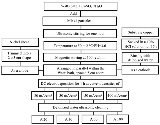
Figure 1.
The flowchart of different plating preparation processes.
The schematic diagram of the electrodeposition apparatus and reaction mechanism is illustrated in Figure 2. The electrolyte temperature was precisely controlled using a water bath to ensure homogeneous thermal distribution. Under the applied electric field, the pure Ni anode dissolves, releasing Ni2+ ions into the electrolyte, which subsequently migrate toward the cathode. Near the cathode, these Ni2+ ions acquire electrons and undergo reduction to metallic Ni. During this reduction process, randomly dispersed CeO2 particles in the electrolyte are simultaneously entrapped, ultimately leading to the formation of the NiCo-CeO2 composite coating.
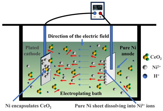
Figure 2.
Schematic diagram of the electrodeposition apparatus and reaction mechanism. The red arrows indicate the random diffusion of CeO2 particles in the electrolyte (multidirectional movement). The blue arrows indicate the direction of the applied electric field (unidirectional)
2.2. Characterization
The surface morphology of the electrodeposited coatings was examined using field-emission scanning electron microscopy (FE-SEM, MIRA3, TESCAN, Brno, Czech Republic) and atomic force microscopy (AFM, FastScan Bio, Bruker, Ettlingen, Germany) in tapping mode. Chemical composition analysis was performed on the samples before corrosion via energy-dispersive X-ray spectroscopy (EDS, Oxford Aztec X-MaxN80, Oxford Instruments, Abingdon, UK) to determine elemental distribution. Phase identification and crystallographic analysis were conducted using a Rigaku Ultima IV X-ray diffractometer (XRD, Rigaku Corporation, Tokyo, Japan) with Cu-Kα radiation (λ = 1.5406 Å). Grain orientation and microstructure evolution were further investigated through electron backscatter diffraction (EBSD, Symmetry detector, Oxford Instruments) coupled with the SEM system. A DHV-1000 Vickers microhardness (Beijing Success, Beijing, China) tester was employed to assess coating hardness under a 25 g load with a dwell time of 15 s. Measurements were systematically taken at 36 grid points (6 × 6 matrix) over a 1 cm2 area to generate a hardness distribution map.
Residual stress analysis was performed using a Proto iXRD X-ray diffractometer (Proto Manufacturing, LaSalle, ON, Canada) with a 6 × 6 laser spot array (1 mm diameter per spot) to map stress variations across the coating surface. The measurement was conducted using the XRD sin2ψ method, with the NiCo (311) diffraction peak at approximately 92° 2θ selected for strain analysis due to its high angular sensitivity and reduced susceptibility to strong crystallographic texture. Lattice strain was measured at multiple tilt angles (ψ = 0°, ±18.43°, ±26.57°, ±33.21°, ±39.23°, ±45.00°) and subsequently converted to stress under the plane stress assumption using Hooke’s law.
The X-ray elastic constants (XECs) were calculated assuming quasi-isotropic polycrystalline behavior, adopting the Kröner–Eshelman model, which is widely accepted for face-centered cubic (FCC) alloys. The employed values were ½S2 = 6.02 × 10⁻⁶ MPa−1 and S1 = −1.48 × 10⁻⁶ MPa−1. Under the applied measurement conditions (Cu-Kα radiation), the 95% X-ray penetration depth was estimated to be approximately 5–7 μm, indicating that the measured stress is surface-dominated rather than a through-thickness average. Given that the coating thicknesses range from 21 to 78 μm, the penetration depth is considerably smaller than the coating thickness; therefore, the contribution of the copper substrate to the measured diffraction signal is negligible, and no substrate-related peak interference was detected.
The corrosion resistance was evaluated using a CHI660E electrochemical workstation (Shanghai Chenhua, Shanghai, China) in a 3.5 wt% NaCl electrolyte. A three-electrode cell configuration was adopted, where the coated sample (1 cm2 exposed area) served as the working electrode, a platinum sheet as the counter electrode, and a saturated calomel electrode (SCE, +244 mV vs. SHE) as the reference. Potentiodynamic polarization (P-P) measurements were performed at a sweep rate of 1 mV/s to characterize the electrochemical corrosion behavior and determine the kinetic parameters of the samples.
X-ray photoelectron spectroscopy (XPS) was utilized to examine the corrosion products generated on the coated surfaces following the P-P test. Measurements were carried out with a monochromatic Al Kα source (1486.6 eV), employing an electron emission angle of 90° and an analysis area of 700 μm × 300 μm. Spectral data were processed using the Avantage software (Version 5.9921, Thermo Fisher Scientific, Waltham, MA, USA) suite. To ensure precise binding energy calibration, the C 1s peak was corrected via the work function approach. This method was adopted because traditional referencing techniques can lead to considerable inaccuracies, as adventitious carbon (AdC) exhibits substantial binding energy shifts—up to 1.44 eV—under different coverage conditions, an effect well documented by Hultman and Greczynski [32,33,34]. In accordance with their established correlation between C 1s binding energy shifts and the sample work function , expressed as + ϕSA = 289.58 ± 0.15 eV, calibration was performed to improve reliability [32,33,34]. The work function values were determined by ultraviolet photoelectron spectroscopy (UPS) using He I radiation (hv = 21.2 eV) with an analysis spot size of 55 μm2. Results indicated a work function of 4.76 eV for the A30 coating, which corresponds to a C 1s binding energy of 284.82 eV.
3. Results and Discussion
3.1. Surface Morphology
Figure 3 presents the surface morphology and energy-dispersive X-ray spectroscopy (EDS) analysis of NiCo-CeO2 composite coatings prepared at various current densities. The results demonstrate that all coatings exhibit similar surface topographies, consisting of a Ni matrix with uniformly distributed CeO2 particles. It should be noted that the EDS analysis was performed specifically for the quantitative characterization of the four target elements (Ni, Co, Ce, and O), and other potential impurity elements were not included in the analysis scope. The chemical composition of different coatings was semi-quantitatively determined by EDS and summarized in Table 1. Notably, the Co content in the coatings reaches its maximum when the current density increases from 20 mA/cm2 to 30 mA/cm2. However, further elevation of current density to 50 mA/cm2 leads to a progressive decrease in Co content, with the minimum Co concentration observed at 100 mA/cm2.
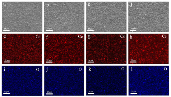
Figure 3.
SEM images and EDS mapping of Ce and O element of NiCo-CeO2 coatings prepared at various current densities: (a,e,i) 20 mA/cm2; (b,f,j) 30 mA/cm2; (c,g,k) 50 mA/cm2; (d,h,l) 100 mA/cm2.

Table 1.
The EDS elemental composition ratio of NiCo-CeO2 coatings prepared at various current densities.
This phenomenon can be attributed to the distinct polarization behaviors of Ni2+ and Co2+ during electrodeposition. As the current density increases from 20 mA/cm2 to 30 mA/cm2, cathodic polarization intensifies, and the reduction rate of cobalt is significantly enhanced, leading to a rapid increase in cobalt content within the coating. Subsequently, when the current density is further increased to 50 mA/cm2 and even 100 mA/cm2, the cathodic overpotential continues to rise. Under such high current density conditions, the reduction process of Co2+ gradually becomes limited by concentration polarization [35]. This is because the migration rate of Co2+ in the solution is relatively slow; when it is rapidly consumed at the cathode surface, the concentration replenishment within the diffusion layer cannot keep pace, leading to a relative decrease in its deposition amount. In contrast, the reduction in Ni2+ remains more strongly controlled by activation polarization and is less affected by diffusion limitations. As a result, the increasing trend of cobalt content tends to level off or even decline at higher current densities.
Furthermore, the Ce content shows a consistent decline with increasing current density, indicating that higher current densities are unfavorable for the effective incorporation of CeO2 particles into the coatings. Regarding the influence of coexisting species on Ni/Co deposition, it should be noted that CeO2 particles are inert and non-conductive ceramic particles that do not participate in electrode reactions. Their incorporation into the coating occurs primarily through physical adsorption and mechanical entrapment, and thus their direct impact on the reduction kinetics of Ni2+ and Co2+ is limited. Other potential coexisting species in the bath are present only in trace amounts, and their effects on the Ni/Co deposition balance are considered negligible. As for the oxygen content detected by EDS, when converted to atomic percentages, the oxygen content in all samples is approximately seven times that of cerium, significantly exceeding the theoretical Ce:O atomic ratio of 1:2 in CeO2. This indicates that, in addition to the oxygen contributed by the incorporated CeO2 particles, a substantial portion of the detected oxygen originates from surface oxide/hydroxide layers (such as NiO, Ni(OH)2) formed on the coatings upon exposure to air. These findings collectively demonstrate that adjusting the current density provides an effective approach to control the Co and CeO2 contents in NiCo-CeO2 composite coatings, thereby regulating both their chemical composition and surface morphology.
To accurately characterize the surface roughness variations among different NiCo-CeO2 composite coatings, atomic force microscopy (AFM) was employed for quantitative assessment. Figure 4 presents the three-dimensional AFM surface topographies of the coatings. The root-mean-square roughness (Rq) and average roughness (Ra) were calculated using Nanoscope analysis software (Version 1.8, Bruker Corporation, Santa Barbara, CA, USA), with detailed data summarized in Table 2. The results reveal that increasing the current density from 20 mA/cm2 to 30 mA/cm2 reduces the surface roughness of the coatings. However, further increasing the current density to 50 mA/cm2 leads to an increase in roughness, which reaches its maximum at 100 mA/cm2. This trend can be explained as follows: At 20 mA/cm2, the higher CeO2 particle content in the coating contributes to increased surface roughness; at 30 mA/cm2, the reduction in CeO2 content, coupled with an increase in Co content, suppresses columnar grain growth and refines the coating microstructure, thereby lowering surface roughness; beyond 30 mA/cm2 (up to 100 mA/cm2), although CeO2 content continues to decrease, the more significant decline in Co content promotes the formation of coarse columnar grains, resulting in a progressive increase in surface roughness. This reveals a non-monotonic dependence of surface roughness on current density, governed by the competing effects of CeO2 incorporation and Co-dominated microstructure evolution, with optimal smoothness achieved at intermediate current densities.
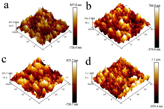
Figure 4.
Three-dimensional AFM images for the NiCo-CeO2 coatings prepared at various current densities: (a) 20 mA/cm2; (b) 30 mA/cm2; (c) 50 mA/cm2; (d) 100 mA/cm2.
Table 2.
Surface roughness of NiCo–CeO2 coatings prepared at various current densities.
3.2. Microstructure
The phase composition of NiCo-CeO2 composite coatings prepared at different current densities was characterized by X-ray diffraction (XRD) analysis. As a critical parameter in electrodeposition, current density significantly influences the coating composition due to the distinct reduction potentials of Ni2+ and Co2+ in the electrolyte, consequently affecting the microstructure evolution. Figure 5 presents the XRD patterns of NiCo-CeO2 composite coatings prepared at different current densities. The patterns show three characteristic diffraction peaks at approximately 44.5°, 51.85°, and 76.38°, which are indexed to the (111), (200), and (220) crystallographic planes of the face-centered cubic (fcc) NiCo solid-solution phase (JCPDS #04-0850). Additionally, distinct peaks observed at 28.5°, 33.0°, 47.4°, and 56.3° correspond, respectively, to the (111), (200), (220), and (311) planes of the fluorite-structured CeO2 phase (JCPDS #34-0394). These results confirm the biphasic composition of all prepared coatings. The XRD patterns in Figure 5 also reveal a systematic shift in the peak positions of the NiCo solid-solution phase with increasing current density. For FCC NiCo alloys, the lattice parameter expands as the cobalt content rises due to the slightly larger atomic radius of Co compared to Ni, leading to a corresponding shift in diffraction peaks toward lower angles. Notably, the angular position of the most intense peak, corresponding to the (111) plane of the NiCo phase, varies consistently across the coatings: it is observed at 44.46° for A20, 44.40° for A30, 44.46° for A50, and 44.48° for A100. This angular variation, though subtle, reflects changes in the lattice parameter induced by the varying Co content in the solid-solution matrix, which is in turn governed by the applied current density during electrodeposition. The observed peak shifts thus provide indirect but clear evidence of composition-dependent lattice distortion within the NiCo phase, corroborating the influence of electrodeposition parameters on the coating’s structural characteristics. To quantitatively evaluate the texture evolution of the NiCo-CeO2 coatings, the relative XRD intensity ratio of the (111) to (200) peaks, denoted as I(111)/I(200), was calculated for each coating. This ratio serves as a reliable indicator of the preferred crystallographic orientation, particularly reflecting the strength of the [200] fiber texture. The calculated I(111)/I(200) values for the A20, A30, A50, and A100 coatings are 8.864, 3.530, 1.348, and 0.707, respectively. Notably, this ratio exhibits a monotonic decrease with increasing current density, indicating a progressive strengthening of the [200] fiber texture. This quantitative trend confirms that higher current densities promote the development of (200)-oriented grains, while lower current densities favor the retention of the close-packed (111) plane. The finding provides critical guidance for optimizing the coating microstructure through current density regulation.
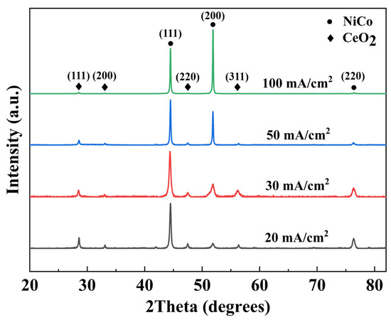
Figure 5.
XRD patterns of NiCo-CeO2 coatings prepared at various current densities.
As shown in Figure 6, the A20 coating (20 mA/cm2) exhibits a cross-sectional thickness of approximately 21 μm. The Forward Scatter Diffraction (FSD) map reveals extensive gray contrast regions, corresponding to uniformly distributed CeO2 particles, while black regions in the inverse pole figure (IPF) map represent unresolved CeO2 agglomerates. The IPF orientation map demonstrates highly concentrated grain orientations, as reflected in the corresponding inverse pole figure triangle, indicating strong crystallographic texture. Despite abundant CeO2 incorporation, the microstructure lacks uniformity due to pronounced preferred orientation.
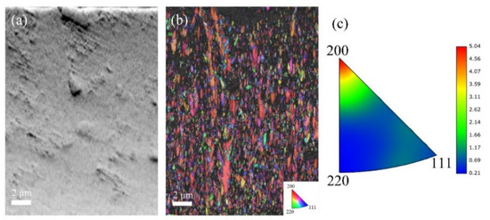
Figure 6.
EBSD data for the cross-section analysis of A20 coatings: (a) FSD map; (b) IPF map; and (c) inverse pole figure.
With increasing current density to 30 mA/cm2 (Figure 7), the A30 coating shows an increased thickness of 24 μm and a notable reduction in gray contrast areas, suggesting decreased CeO2 incorporation. The IPF map reveals significantly more randomized grain orientations compared to A20, with the inverse pole figure triangle displaying a dispersed orientation distribution. This coating exhibits the weakest texture intensity among all samples, accompanied by fine and homogeneous grain morphology.
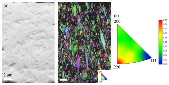
Figure 7.
EBSD data for the cross-section analysis of A30 coatings: (a) FSD map; (b) IPF map; and (c) inverse pole figure.
For the A50 coating (50 mA/cm2, Figure 8), the cross-sectional thickness further increases to 42 μm, while CeO2 particles remain uniformly distributed. The microstructure consists predominantly of fine, equiaxed grains with minimal columnar features. However, the IPF map indicates moderately intensified texture relative to A30, as evidenced by a slight clustering of orientations in the inverse pole figure triangle. The coating retains better microstructural homogeneity than A20, yet shows early signs of texture development.
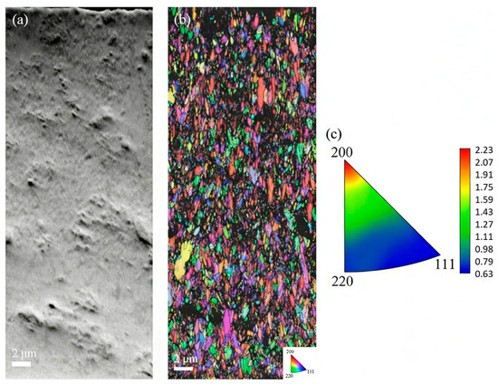
Figure 8.
EBSD data for the cross-section analysis of A50 coatings: (a) FSD map; (b) IPF map; and (c) inverse pole figure.
At the highest current density of 100 mA/cm2 (Figure 9), the A100 coating reaches a substantial thickness of 78 μm, consistent with a significantly accelerated electrodeposition rate. The FSD map reveals sparsely distributed CeO2 particles, and the IPF map exhibits coarse, highly aligned columnar grains with a pronounced preferred orientation. The inverse pole figure triangle shows strong clustering of orientations, confirming the development of an intense texture pattern. The microstructure is characterized by severe heterogeneity and excessive columnar growth.
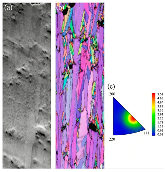
Figure 9.
EBSD data for the cross-section analysis of A100 coatings: (a) FSD map; (b) IPF map; and (c) inverse pole figure.
Systematic EBSD and XRD analyses reveal a clear current density–microstructure relationship. At low current density (20 mA/cm2), high CeO2 incorporation is achieved, but insufficient Co content fails to disrupt preferred grain growth, resulting in strong texture. Moderate current density (30 mA/cm2) yields the highest Co content, which effectively suppresses preferred orientation and refines grain size, producing optimal microstructural homogeneity with the weakest texture. Further increasing current density (50–100 mA/cm2) reduces both Co and CeO2 contents, progressively diminishing the grain-refining effect and permitting excessive columnar growth accompanied by continuous texture strengthening. These findings establish that current density governs microstructural evolution primarily through its regulation of Co content, with an optimal window at 30 mA/cm2 for achieving the weakest texture and highest homogeneity.
3.3. Internal Stress
Based on the previous analysis of the effect of electrodeposition current density on the microstructure of composite coatings, it is evident that current density also significantly influences the internal stress of the coatings [19,36]. Therefore, investigating the role of current density in coating internal stress is of considerable significance. Figure 10 and Figure 11 present the internal stress distribution and average internal stress of NiCo-CeO2 composite coatings prepared at different current densities.
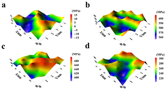
Figure 10.
Surface internal stress distribution of NiCo-CeO2 coatings prepared at various current densities: (a) 20 mA/cm2; (b) 30 mA/cm2; (c) 50 mA/cm2; and (d) 100 mA/cm2.
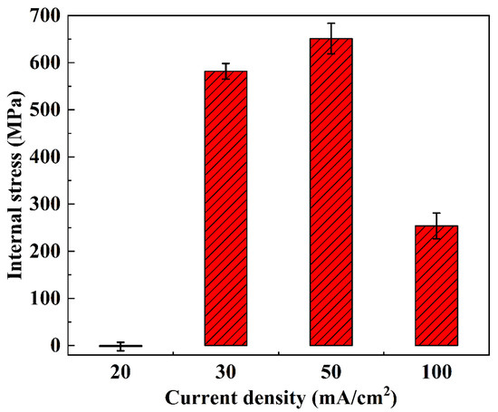
Figure 11.
Surface average internal stress of NiCo-CeO2 coatings prepared at various current densities.
As shown in Figure 10a and Figure 11, the internal stress of the A20 coating ranges from −16 MPa to 17 MPa, with an average stress of −2.22 MPa and an amplitude of 9.11 MPa. According to Figure 10b and Figure 11, the A30 coating exhibits an internal stress range of 555 MPa to 608 MPa, with an average stress of 581.67 MPa and an amplitude of 16.51 MPa. Figure 10c and Figure 11 reveal that the A50 coating has an internal stress range of 581 MPa to 701 MPa, an average stress of 651 MPa, and an amplitude of 32.42 MPa. Finally, Figure 10d and Figure 11 demonstrate that the A100 coating displays an internal stress range of 206 MPa to 304 MPa, with an average stress of 253.58 MPa and an amplitude of 27.39 MPa.
In general, as the current density increases from 20 mA/cm2 to 50 mA/cm2, the internal stress of the NiCo-CeO2 composite coatings progressively rises. This behavior arises from the following factors: (1) Higher current density increases the external energy input, promoting nucleation of metal ions in the electrolyte, thereby significantly enhancing the nucleation rate and refining the grain size of the coating. This refinement increases lattice distortion, ultimately elevating internal stress. (2) Additionally, the electrodeposition rate accelerates with increasing current density, leading to more unbalanced growth during coating formation, which further intensifies internal stress.
However, when the current density reaches 100 mA/cm2, the internal stress of the NiCo-CeO2 coating decreases. Wang et al. investigated the relationship between Co content and internal stress in NiCo alloys, demonstrating that reduced Co content in NiCo-CeO2 coatings decreases lattice mismatch, thereby lowering internal stress [37]. Combining this finding with our earlier analysis of the A100 coating’s composition, we conclude that the stress reduction at 100 mA/cm2 is primarily due to the decline in Co content under high current density, which reduces lattice distortion and consequently diminishes internal stress. Furthermore, the substantial decrease in CeO2 particle content in the A100 coating also contributes to reduced lattice distortion, further promoting stress relief.
Notably, only the A20 coating exhibits a negative average internal stress value, indicating that lower current density facilitates the transition from tensile to compressive stress in NiCo-CeO2 composite coatings. This shift occurs because, at lower current densities, the electrodeposition process proceeds under more balanced growth conditions, allowing internal stress to be released during electrodeposition, thereby minimizing residual stress.
It is noteworthy that the A30 coating exhibits a relatively high residual tensile stress (~582 MPa), which could potentially affect its interfacial adhesion and long-term stability for engineering applications. While a comprehensive evaluation of adhesion and integrity (e.g., via scratch or bend tests) falls beyond the primary scope of this foundational study (which focuses on establishing the current-density-dependent microstructure-property relationships), the identification of this high-stress state is itself a significant finding. It highlights a key challenge for potential application: achieving the synergistic hardness and corrosion resistance observed at optimal current density while mitigating concomitant high stress. Consequently, developing low-stress, high-performance NiCo-CeO2 composite coatings through advanced process modulation (e.g., pulsed electrodeposition, additive engineering, or post-treatment) represents a crucial direction for future research.
In summary, electrodeposition current density influences the internal stress of composite coatings through multiple mechanisms: (1) modulating coating growth rate, (2) varying external energy input, (3) altering Co content, and (4) changing CeO2 particle incorporation. These factors collectively determine the overall stress state of the coating, providing critical insights for optimizing electrodeposition parameters to achieve desired mechanical properties. However, the microscale internal stress behavior, especially the dual role of CeO2 particles as either local stress concentrators or stress-relief sites depending on their distribution and interfacial characteristics, represents an important direction for future research. Integrating such microscopic insights with the macroscopic stress framework will provide even more critical guidance for precisely optimizing electrodeposition parameters to achieve tailored mechanical properties and enhanced coating reliability.
3.4. Microhardness
As previously established, the electrodeposition current density significantly affects both the composition and microstructure of NiCo-CeO2 composite coatings, which in turn profoundly influences their hardness. Furthermore, current density also determines the texture characteristics of the coatings, and different texture types exhibit distinct effects on hardness [15]. Therefore, this section systematically investigates the impact of current density on the hardness of NiCo-CeO2 composite coatings.
The hardness characteristics of NiCo-CeO2 composite coatings prepared at different current densities are presented in Figure 12 and Figure 13. The A20 coating electrodeposited at 20 mA/cm2 exhibits a hardness ranging from 366.6 to 441.4 HV, with an average value of 413.6 HV. When the current density increases to 30 mA/cm2, the A30 coating demonstrates improved hardness performance, showing values between 410.7 and 483.5 HV (average: 449.8 HV). However, further increasing the current density to 50 mA/cm2 results in decreased hardness for the A50 coating (306.1–362.5 HV, average: 333.4 HV). This downward trend continues for the A100 coating electrodeposited at 100 mA/cm2, which displays the lowest hardness values, ranging from 254.7 to 325.6 HV (average: 288.8 HV).
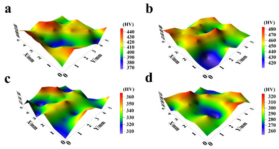
Figure 12.
The microhardness distribution of NiCo-CeO2 coatings prepared at different current densities: (a) 20 mA/cm2; (b) 30 mA/cm2; (c) 50 mA/cm2; and (d) 100 mA/cm2.
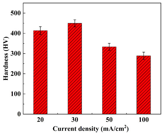
Figure 13.
The average microhardness of NiCo-CeO2 coatings prepared at different current densities.
The hardness evolution reveals a non-monotonic dependence on current density: hardness increases from 20 to 30 mA/cm2 but decreases continuously at higher current densities (50–100 mA/cm2). This behavior can be explained by three competing factors: composition, microstructure, and crystallographic texture. The A30 coating achieves peak hardness due to its optimal Co content (30.4%, Section 3.1), which enhances solid solution strengthening, combined with effective dispersion strengthening from CeO2 particles. Furthermore, the predominance of closely packed (111) planes in the A30 coating contributes to its superior hardness, as these planes exhibit higher atomic packing density compared to the more loosely packed (200) planes. In contrast, the reduced hardness in A50 and A100 coatings correlates with their decreased Co (23.7% and 14.5%, respectively) and CeO2 (6.2% and 5.1%) contents, along with an increasing proportion of the less densely packed (200) planes at higher current densities.
The current density therefore governs coating hardness through its simultaneous influence on chemical composition and crystallographic texture. Moderate current densities (30 mA/cm2) optimize both Co/CeO2 incorporation and (111) texture development, while excessive current densities (>30 mA/cm2) degrade these characteristics through reduced Co content and unfavorable texture evolution. These findings demonstrate that careful current density selection can effectively tune the hardness of NiCo-CeO2 composite coatings by controlling their fundamental strengthening mechanisms.
3.5. Electrochemical Tests
The corrosion resistance of NiCo-CeO2 composite coatings serves as a critical performance metric for protecting metallic substrates from corrosive attack and extending coating service life [15]. Therefore, investigating the influence of current density on the corrosion resistance of NiCo-CeO2 composite coatings holds significant importance. Potentiodynamic polarization (P-P) testing is widely employed in electrochemical studies to evaluate the corrosion resistance of composite coatings. This section accordingly assesses the corrosion behavior through analysis of the obtained P-P curves and electrochemical parameters. The primary reactions occurring at the coating surface are as follows:
Ni → 2e− + Ni2+
The primary reactions occurring on the platinum counter electrode surface include:
O2 + 2H2O + 4e− → 4OH−
The corrosion resistance of NiCo-CeO2 composite coatings demonstrates strong dependence on electrodeposition current density, as evidenced by the potentiodynamic polarization (P-P) curves presented in Figure 14. Characteristic regions, including active dissolution, passivation, and transpassivation zones, are observable in the P-P curves of all composite coatings, which is a phenomenon extensively documented in the literature. Within the passivation region, the corrosion current density remains stable despite increasing applied potential, attributable to the formation of oxide-dominated passive films such as nickel hydroxide (Ni(OH)2), nickel oxide (NiO), and cobalt oxide (CoO) on the coating surface. This underscores the importance of investigating methods to enhance passive film formation for improved corrosion resistance.
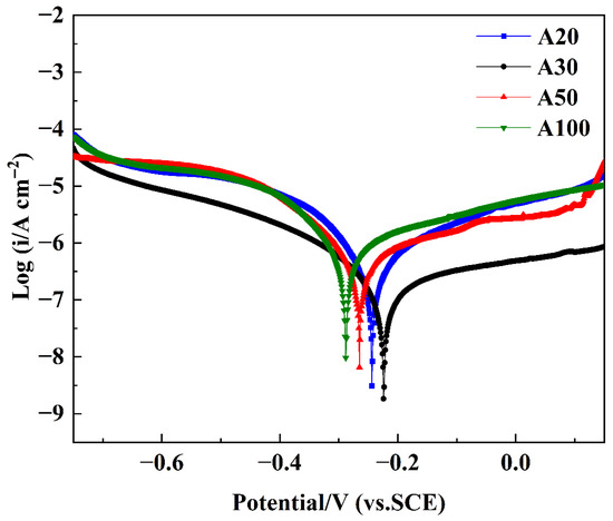
Figure 14.
P-P curves of NiCo-CeO2 coatings prepared at different current densities.
Figure 14 displays the P-P curves of NiCo-CeO2 composite coatings prepared at various current densities, enabling systematic evaluation of their corrosion resistance. Quantitative corrosion parameters were obtained through Tafel extrapolation using CHI660 electrochemical software (CHI660 software, Version 14.10, Shanghai Chenhua, Shanghai, China), with corrosion potential (Ecorr) and corrosion current density (icorr) values tabulated in Table 3. The data reveals a consistent trend: Ecorr progressively increases from A100 to A50, A20, and finally A30 coatings, while icorr shows a corresponding sequential decrease. According to Faraday’s law, the corrosion current density is directly proportional to the corrosion rate, which indicates gradually reduced corrosion rates from the A100 to the A30 coating, directly reflecting their enhanced corrosion resistance performance.
Table 3.
P-P parameters of NiCo-CeO2 coatings prepared at different current densities.
Among all coatings, the A30 sample exhibited the most noble corrosion potential and the lowest corrosion current density, indicating superior corrosion resistance. Therefore, it was selected as the representative coating for XPS analysis after potentiodynamic polarization testing to elucidate the chemical composition and oxidation states of the passive film formed under optimal electrodeposition conditions. As shown in Figure 15a, the full-range XPS survey spectra display distinct photoelectron peaks corresponding to oxygen (O 1s), cobalt (Co 2p), nickel (Ni 2p), cerium (Ce 3d), sodium (Na KL1), chlorine (Cl 2p), silicon (Si 2s), and nitrogen (N 1s), confirming the presence of these elements on the corroded surface. The Cl 2p peak (located at approximately 198–200 eV) and the Na KL1 Auger peak (~497–508 eV) are consistent with residual NaCl surface species, likely introduced during sample preparation or electrochemical testing. The presence of a Si 2s peak (~150–155 eV) suggests minor silicon incorporation, which may originate from substrate diffusion or environmental exposure. Notably, the N 1s signal (~395–405 eV) confirms nitrogen doping within the coating, in agreement with the anticipated effects of the plasma treatment process.
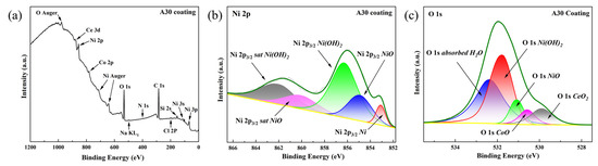
Figure 15.
(a) Full-range XPS spectra of A30 coating after corrosion tests, (b) Ni 2p3/2 spectra of corrosion products of A30 coating, (c) O 1s spectra of corrosion products of A30 coating.
For more detailed chemical state analysis, high-resolution spectra were acquired and carefully fitted. The Ni 2p3/2 spectrum (Figure 15b) was deconvoluted into three contributions: metallic nickel (Ni0) with its main peak at 853.0 eV [38]; nickel oxide (NiO), characterized by a principal peak at 855.0 eV [39] and its characteristic satellite at 860.4 eV [40]; and nickel hydroxide (Ni(OH)2), identified by a main peak at 856.1 eV [41] and a corresponding satellite at 861.7 eV [41].
Similarly, the high-resolution O 1s spectrum of the A30 coating corrosion products (Figure 15c) was deconvoluted, revealing five distinct oxygen-containing species: adsorbed water (H2O) represented by a broad peak at 532.8 eV [42]; nickel hydroxide (Ni(OH)2) with a characteristic peak at 531.7 eV [43]; nickel oxide (NiO) at 531.0 eV [40]; cobalt oxide (CoO) at 530.4 eV [44]; and cerium oxide (CeO2) with its signature peak at 529.6 eV [45]. Collectively, these XPS results confirm the formation of a substantial, mixed metal-oxide/hydroxide passivation layer on the A30 coating surface, which functions as an effective barrier against further corrosion.
For NiCo-CeO2 composite coatings, the corrosion resistance is primarily determined by four factors: the content of Co and CeO2 in the coating, phase structure, grain size, and grain orientation. The current density mainly affects the corrosion resistance by influencing the Co and CeO2 content, which subsequently alters the phase structure, grain size and grain orientation. In this study, the NiCo alloy exists as a single-phase structure. Increasing the content of both Co and CeO2 in the NiCo-CeO2 composite coatings helps refine the grain size and improve microstructural homogeneity. It is inferred from previous studies [30,36] that the presence of well-dispersed CeO2 particles may facilitate the formation of micro-galvanic cells between the ceramic phase and the metallic matrix, which could promote a more uniform corrosion mode and potentially contribute to enhanced corrosion resistance. Additionally, the (111) plane is the closely packed plane of the coating, and its corrosion resistance is superior to that of the more loosely packed (200) plane. Therefore, a higher proportion of (111) planes on the coating surface also contributes to improved corrosion resistance.
The corrosion resistance of NiCo-CeO2 coatings exhibits a strong dependence on current density, with the A30 coating (30 mA/cm2) demonstrating superior performance and the A100 coating (100 mA/cm2) the poorest. This trend is directly correlated with current-density-induced variations in Co content, CeO2 incorporation, grain size, texture intensity, and surface crystallographic orientation.
As analyzed in Section 3.1, the A30 coating achieves the optimal combination of microstructural attributes: the highest Co content (30.4%), finest grain size, weakest texture intensity, and a predominantly (111)-oriented surface. All these factors contribute to its superior corrosion resistance—consistent with previous studies—making the A30 coating the most corrosion-resistant among all samples [30,36].
The A20 coating contains 24.5% Co but has the highest CeO2 content (9.4%). EBSD analysis shows that the A20 coating has relatively fine grains, which is beneficial for corrosion resistance. However, its high texture intensity is unfavorable for achieving a uniform microstructure and consequently detrimental to corrosion resistance. On the other hand, the A20 coating has the highest proportion of (111) planes, which improves corrosion resistance. Due to the presence of these unfavorable factors for corrosion resistance, the A20 coating shows inferior performance compared to the A30 coating.
At current densities of 50 mA/cm2 and above, corrosion resistance progressively declines. The A50 coating exhibits marginally reduced Co content (23.7%), coarsened columnar grains, and a decreased fraction of (111) surface planes. The A100 coating represents the extreme case, characterized by the lowest Co (14.5%) and CeO2 (5.1%) contents, excessive columnar growth, the strongest [200] texture, and minimal (111) surface orientation. These severely degraded microstructural features collectively account for its poorest corrosion performance.
In conclusion, current density influences corrosion resistance primarily through its regulation of Co and CeO2 co-deposition, which subsequently influences grain refinement, texture evolution, and surface crystallography. The optimal performance at 30 mA/cm2 reflects a balanced synergy among these factors, while deviations to either lower or higher current densities disrupt this balance and compromise corrosion protection.
Furthermore, according to Refs. [30,36], current density likely influences corrosion performance not only through the observed microstructural and compositional changes but also by potentially altering the chemistry and defect structure of the passive film itself. Therefore, while this study establishes a clear correlation between processing parameters, structure, and corrosion behavior, a systematic XPS-based comparison of the passive films formed on coatings deposited at different current densities is identified as a crucial next step to fully elucidate the underlying electrochemical protection mechanisms.
4. Conclusions
This study systematically elucidates how electrodeposition current density influences the composition, microstructure, mechanical properties, and corrosion resistance of NiCo-CeO2 composite coatings. The main findings are summarized as follows:
- The Co and CeO2 contents in the coatings exhibit a strong dependence on current density, which in turn governs the phase composition and surface morphology. Increasing CeO2 incorporation combined with lower Co content leads to surface roughening. The smoothest surface morphology is achieved at 30 mA/cm2 (A30) among all coatings, whereas the highest surface roughness is observed at 100 mA/cm2 (A100).
- Optimal current density (30 mA/cm2) yields the highest Co incorporation among all coatings, which significantly weakens the crystallographic texture and promotes microstructural homogeneity. In contrast, further increases in current density (50–100 mA/cm2) reduce both Co and CeO2 contents, leading to texture reinforcement and increased structural anisotropy.
- Residual stress states are highly sensitive to deposition conditions. The A20 coating exhibits near-stress-free characteristics with a low compressive stress of −2.22 MPa, while the A50 coating develops a pronounced tensile stress of 651 MPa, indicating a strong correlation between current density, Co/CeO2 content, and internal stress evolution.
- Microhardness is strongly enhanced by increased Co and CeO2 co-deposition and by the dominance of the (111) crystallographic plane. The A30 coating achieves the highest hardness of 449.8 HV, whereas the A100 coating, characterized by reduced Co/CeO2 content and weakened (111) texture, exhibits the lowest hardness of 288.8 HV among all coatings.
- The synergistic effects of grain refinement, (111) preferential orientation, and compositional uniformity, which are optimized at a moderate current density of 30 mA/cm2, endow the A30 coating with an excellent combination of mechanical integrity and corrosion resistance. It displays the most noble corrosion potential (–224 mV vs. SCE) and the lowest corrosion current density (0.225 μA/cm2) among all coatings, confirming its superior passivation capability among all tested coatings.
These findings establish a clear process–microstructure–property framework for the current density-controlled electrodeposition of NiCo-CeO2 composite coatings and provide actionable guidance for designing protective coatings with tailored performance.
Author Contributions
Conceptualization, S.Y.; Methodology, S.Y.; Investigation, S.Y. and Q.S.; Resources, S.Y. and Q.S.; Data curation, S.Y. and H.Z.; Writing—original draft, S.Y.; Writing—review & editing, S.Y.; Supervision, X.Z. and C.J.; Funding acquisition, S.Y., X.Z. and H.Z. All authors have read and agreed to the published version of the manuscript.
Funding
This work was financially supported by the National Natural Science Foundation of China (Grants U22A20207, 52475477, 52335010 and 52505506), the Science and Technology Commission of Shanghai Municipality (Grant 23PJ1406600), and China Postdoctoral Science Foundation: 2025M781316.
Institutional Review Board Statement
Not applicable.
Informed Consent Statement
Not applicable.
Data Availability Statement
The data presented in this study are available on request from the corresponding author.
Acknowledgments
The authors would like to express their sincere gratitude to Qinyao Sun for her valuable assistance in SEM characterization.
Conflicts of Interest
The authors declare that they have no known competing financial interests or personal relationships that could have appeared to influence the work reported in this paper.
References
- Feng, J.; Wang, J.; Yang, K.; Rong, J. Microstructure and performance of YTaO4 coating deposited by atmospheric plasma spraying on TC4 titanium alloy surface. Surf. Coat. Technol. 2022, 431, 128004. [Google Scholar] [CrossRef]
- Cabral, A.T.; Junior, A.R.G.O.; Koga, G.Y.; Rigoli, I.C.; Rocha, C.L.F.; Souza, C.A.C. Electrodeposited zinc cellulose nanocrystals composite coatings: Morphology, structure, corrosion resistance and electrodeposition process. J. Mater. Res. Technol. 2024, 33, 1569–1580. [Google Scholar] [CrossRef]
- Mundotiya, B.M.; Shah, A.; Burdak, P.; Bairwa, S.K. Development and corrosion behavior of electrodeposited FeCoNiMoW and FeCoNiMoWCr high entropy alloy coatings. J. Alloys Compd. 2025, 1020, 179466. [Google Scholar] [CrossRef]
- Singh, A.P.; Srivastava, C. Role of solute clustering and grain orientation on electrochemical degradation of Sn-Bi coatings electrodeposited at different current densities. Electrochim. Acta 2024, 477, 143826. [Google Scholar] [CrossRef]
- Zhang, W.; Du, S.; Li, B.; Mei, T.; Miao, Y.; Chu, H.; Wang, J. Synthesis and characterization of TiN nanoparticle reinforced binary Ni-Co alloy coatings. J. Alloys Compd. 2021, 865, 158722. [Google Scholar] [CrossRef]
- Tang, R.; Joshi, G.R.; Zhao, H.; Venkateswaran, S.P.; Withers, P.J.; Xiao, P. The influence of electrodeposited Ni-Co alloy coating microstructure on CO2 corrosion resistance on X65 steel. Corros. Sci. 2020, 167, 108485. [Google Scholar] [CrossRef]
- Safavi, M.S.; Tanhaei, M.; Ahmadipour, M.F.; Ghaffari Adli, R.; Mahdavi, S.; Walsh, F.C. Electrodeposited Ni-Co alloy-particle composite coatings: A comprehensive review. Surf. Coat. Technol. 2020, 382, 125153. [Google Scholar] [CrossRef]
- Karimzadeh, A.; Aliofkhazraei, M.; Walsh, F.C. A review of electrodeposited Ni-Co alloy and composite coatings: Microstructure, properties and applications. Surf. Coat. Technol. 2019, 372, 463–498. [Google Scholar] [CrossRef]
- Shu, D.; Dai, S.; Wang, G.; Si, W.; Xiao, P.; Cui, X.; Chen, X. Influence of CeO2 content on WC morphology and mechanical properties of WC/Ni matrix composites coating prepared by laser in-situ synthesis method. J. Mater. Res. Technol. 2020, 9, 11111–11120. [Google Scholar] [CrossRef]
- Gómez, M.J.; Lucci, R.O.; Franceschini, E.A.; Lacconi, G.I. Effect of TiO2 content on Ni/TiO2 composites electrodeposited on SS316L for hydrogen evolution reaction. Electrochim. Acta 2021, 378, 138136. [Google Scholar] [CrossRef]
- Ghazanlou, S.I.; Ahmadiyeh, S.; Yavari, R. Investigation of pulse electrodeposited Ni–Co/SiO2 nanocomposite coating. Surf. Eng. 2017, 33, 337–347. [Google Scholar] [CrossRef]
- Wang, Z.; Liu, H.; Huang, J.; Zhuo, S.; Wu, Y.; Wang, G.; Zheng, Z.; Qiu, Z.; Zeng, D. Improving wear and corrosion resistance of HVAF sprayed 316L stainless steel coating by adding TiB2 ceramic particles and CeO2. J. Mater. Res. Technol. 2024, 31, 1313–1325. [Google Scholar] [CrossRef]
- KasÏpar, J.; Fornasiero, P.; Graziani, M. Use of CeO2-based oxides in the three-way catalysis. Catal. Today 1999, 50, 285–298. [Google Scholar] [CrossRef]
- Cui, C.; Wu, M.; Miao, X.; Zhao, Z.; Gong, Y. Microstructure and corrosion behavior of CeO2/FeCoNiCrMo high-entropy alloy coating prepared by laser cladding. J. Alloys Compd. 2022, 890, 161826. [Google Scholar] [CrossRef]
- You, S.; Zhang, X.; Jiang, C.; Zhang, H. Role of microscale and nanoscale CeO2 particles on the microstructures, internal stress and properties in electrodeposited NiCo alloy platings. Vacuum 2025, 240, 114499. [Google Scholar] [CrossRef]
- Chauhan, H.R.; Saladi, S.; Variya, S.; Solanki, A.; Tailor, S.; Sooraj, K.P.; Ranjan, M.; Joshi, S. Role of micro- and nano-CeO2 reinforcements on characteristics and tribological performance of HVOF sprayed Cr3C2-NiCr coatings. Surf. Coat. Technol. 2023, 467, 129684. [Google Scholar] [CrossRef]
- Fathyunes, L.; Mohtadi-Bonab, M.A. Co-electrodeposition of superhydrophobic NiCo/CeO2 coating with hierarchical nano/micro structure for corrosion protection of plain carbon steel. Mater. Today Commun. 2024, 39, 108851. [Google Scholar] [CrossRef]
- Saha, R.K.; Khan, T.I. Effect of applied current on the electrodeposited Ni–Al2O3 composite coatings. Surf. Coat. Technol. 2010, 205, 890–895. [Google Scholar] [CrossRef]
- Góral, A.; Nowak, M.; Berent, K.; Kania, B. Influence of current density on microstructure and properties of electrodeposited nickel-alumina composite coatings. J. Alloys Compd. 2014, 615, S406–S410. [Google Scholar] [CrossRef]
- Guo, C.; Zuo, Y.; Zhao, X.; Zhao, J.; Xiong, J. The effects of electrodeposition current density on properties of Ni–CNTs composite coatings. Surf. Coat. Technol. 2008, 202, 3246–3250. [Google Scholar] [CrossRef]
- Wang, L.; Ren, J.; Zhao, Y.; Ji, V.; Liu, H.; Liu, M.; Wang, Z.; Jiang, C.; Wang, Z. Effect of Ti microparticles on the microstructure and properties of Ni-Ti composite coating prepared by electrodeposition. J. Alloys Compd. 2022, 908, 164313. [Google Scholar] [CrossRef]
- Wang, L.; Xing, S.; Shen, Z.; Liu, H.; Jiang, C.; Ji, V.; Zhao, Y. The synergistic role of Ti microparticles and CeO2 nanoparticles in tailoring microstructures and properties of high-quality Ni matrix nanocomposite coating. J. Mater. Sci. Technol. 2022, 105, 182–193. [Google Scholar] [CrossRef]
- Zhou, X.; Wang, Y.; Liang, Z.; Jin, H. Electrochemical deposition and nucleation/growth mechanism of Ni-Co-Y2O3 multiple coatings. Materials 2018, 11, 1124. [Google Scholar] [CrossRef] [PubMed]
- You, S.; Xing, S.; Jiang, C. The influence of CeO2 particle with various sizes on the microstructure and properties of electrodeposited Ni-CeO2 composite coatings. Mater. Charact. 2023, 205, 113327. [Google Scholar] [CrossRef]
- Erler, F.; Jakob, C.; Romanus, H.; Spiess, L.; Wielage, B.; Lampke, T.; Steinhäuser, S. Interface behaviour in nickel composite coatings with nano-particles of oxidic ceramic. Electrochim. Acta 2003, 48, 3063–3070. [Google Scholar] [CrossRef]
- Gül, H.; Kılıç, F.; Aslan, S.; Alp, A.; Akbulut, H. Characteristics of electro-co-deposited Ni–Al2O3 nano-particle reinforced metal matrix composite (MMC) coatings. Wear 2009, 267, 976–990. [Google Scholar] [CrossRef]
- Guo, A.X.Y.; Wu, Y.; Wang, Z.; Xiao, Q.; Cao, S.C. Strengthening and toughening of Ti–Nb films by adjusting internal stress. Vacuum 2022, 202, 111127. [Google Scholar] [CrossRef]
- Ortolani, M.; Zanella, C.; Azanza Ricardo, C.L.; Scardi, P. Elastic grain interaction in electrodeposited nanocomposite nickel matrix coatings. Surf. Coat. Technol. 2012, 206, 2499–2505. [Google Scholar] [CrossRef]
- Pathak, S.; Guinard, M.; Vernooij, M.G.C.; Cousin, B.; Wang, Z.; Michler, J.; Philippe, L. Influence of lower current densities on the residual stress and structure of thick nickel electrodeposits. Surf. Coat. Technol. 2011, 205, 3651–3657. [Google Scholar] [CrossRef]
- Wang, L.; Chen, M.; Liu, H.; Jiang, C.; Ji, V.; Moreira, F. Optimisation of microstructure and corrosion resistance of Ni-Ti composite coatings by the addition of CeO2 nanoparticles. Surf. Coat. Technol. 2017, 331, 196–205. [Google Scholar] [CrossRef]
- You, S.; Xing, S.; Jiang, C. Synergistic optimization of microstructures and properties of electrodeposited Ni–CeO2 composite coatings with CeO2 microparticles and CeO2 nanoparticles. J. Mater. Res. Technol. 2024, 29, 181–195. [Google Scholar] [CrossRef]
- Greczynski, G.; Hultman, L. C 1s Peak of Adventitious Carbon Aligns to the Vacuum Level: Dire Consequences for Material’s Bonding Assignment by Photoelectron Spectroscopy. Chemphyschem 2017, 18, 1507–1512. [Google Scholar] [CrossRef]
- Greczynski, G.; Hultman, L. Reliable determination of chemical state in x-ray photoelectron spectroscopy based on sample-work-function referencing to adventitious carbon: Resolving the myth of apparent constant binding energy of the C 1s peak. Appl. Surf. Sci. 2018, 451, 99–103. [Google Scholar] [CrossRef]
- Greczynski, G.; Hultman, L. X-ray photoelectron spectroscopy: Towards reliable binding energy referencing. Prog. Mater. Sci. 2020, 107, 100591. [Google Scholar] [CrossRef]
- Fan, C.; Piron, D.L. Study of anomalous nickel-cobalt electrodeposition with different electrolytes and current densities. Electrochim. Acta 1996, 41, 1713–1719. [Google Scholar] [CrossRef]
- Zhao, Y.; Wang, L.; Sun, Y.; Liu, H.; Jiang, C.; Ji, V.; Li, W. Influences of Al and Ti particles on microstructure, internal stress and property of Ni composite coatings. J. Alloys Compd. 2019, 793, 314–325. [Google Scholar] [CrossRef]
- Wang, L.; Gao, Y.; Xue, Q.; Liu, H.; Xu, T. Graded composition and structure in nanocrystalline Ni–Co alloys for decreasing internal stress and improving tribological properties. J. Phys. D Appl. Phys. 2005, 38, 1318. [Google Scholar] [CrossRef]
- Salvati, L., Jr.; Makovsky, L.E.; Stencel, J.; Brown, F.; Hercules, D.M. Surface spectroscopic study of tungsten-alumina catalysts using X-ray photoelectron, ion scattering, and Raman spectroscopies. J. Phys. Chem. 1981, 85, 3700–3707. [Google Scholar] [CrossRef]
- Matienzo, J.; Yin, L.I.; Grim, S.O.; Swartz, W.E., Jr. X-ray photoelectron spectroscopy of nickel compounds. Inorg. Chem. 1973, 12, 2762–2769. [Google Scholar] [CrossRef]
- Venezia, A.M.; Bertoncello, R.; Deganello, G. X-ray photoelectron spectroscopy investigation of pumice-supported nickel catalysts. Surf. Interface Anal. 1995, 23, 239–247. [Google Scholar] [CrossRef]
- Mansour, A. Characterization of β-Ni(OH)2 by XPS. Surf. Sci. Spectra 1994, 3, 239–246. [Google Scholar] [CrossRef]
- Martensson, N.; Malmqvist, P.; Svensson, S.; Basilier, E.; Pireaux, J.; Gelius, U.; Siegbahn, K. Molecular and solid water-A comparative ESCA study. Nouv. J. Chim. 1977, 1, 191–196. [Google Scholar]
- Kishi, K.; Ikeda, S. X-ray photoelectron spectroscopic study of the reaction of evaporated metal films with chlorine gas. J. Phys. Chem. 1974, 78, 107–112. [Google Scholar] [CrossRef]
- LoáJacono, M. Preparation and characterisation of cobalt–copper hydroxysalts and their oxide products of decomposition. J. Chem. Soc. Faraday Trans. 1992, 88, 311–319. [Google Scholar] [CrossRef]
- Praline, G.; Koel, B.E.; Hance, R.L.; Lee, H.I.; White, J.M. X-ray photoelectron study of the reaction of oxygen with cerium. J. Electron Spectrosc. Relat. Phenom. 1980, 21, 17–30. [Google Scholar] [CrossRef]


Disclaimer/Publisher’s Note: The statements, opinions and data contained in all publications are solely those of the individual author(s) and contributor(s) and not of MDPI and/or the editor(s). MDPI and/or the editor(s) disclaim responsibility for any injury to people or property resulting from any ideas, methods, instructions or products referred to in the content. |
© 2026 by the authors. Licensee MDPI, Basel, Switzerland. This article is an open access article distributed under the terms and conditions of the Creative Commons Attribution (CC BY) license.