1. Introduction
As a clean energy carrier, hydrogen has emerged as the most promising fossil fuel alternative in global energy transition strategies, owing to its abundant reserves (constituting 75% of universal matter), high calorific value (142 mJ/kg), and zero-carbon emission characteristics [
1]. Within hydrogen storage and transportation systems, pipeline transmission has become the preferred method for long-distance, large-scale hydrogen delivery due to its significant economic advantages and exceptional transmission efficiency (capacity reaching 500 × 10
3 m
3/h) [
2,
3]. However, the high permeability of hydrogen atoms (diameter ≈ 0.106 nm) in metallic pipelines, along with associated hydrogen embrittlement (diffusion coefficients ~10
−6 cm
2/s), poses significant risks to the long-term integrity of hydrogen pipelines. While ceramic-based and graphene coatings have shown promising progress in hydrogen barrier research, the development of high-performance protective coatings for large-scale pipelines remains hindered by challenges in cost-effectiveness, process compatibility, and scalable manufacturing. Developing novel coating materials that combine excellent hydrogen barrier properties with engineering applicability holds strategic significance for advancing the safety and industrialization of hydrogen infrastructure.
The development of hydrogen barrier coatings dates back to the late 1970s, when Fower et al. [
4] first proposed the innovative concept of using surface hydrogen permeation barriers to mitigate substrate embrittlement. Compared to expensive pipeline material replacement solutions, coating technology offers distinct economic advantages. Notably, existing research has predominantly focused on natural gas pipeline protection, while dedicated coatings for hydrogen-blended natural gas and pure hydrogen transmission pipeline steels remain in the exploratory phase. In current engineering practice, organic coatings such as epoxy resins can effectively block corrosive media like wet CO
2/H
2S [
5]. For large-scale infrastructure such as underground pipelines, existing coatings fail to meet the requirements, necessitating the development of polymer coatings that can be applied at near-ambient temperatures, cured with low energy consumption, and produced at low cost. While such materials can effectively mitigate hydrogen embrittlement during hydrogen transportation through existing pipelines—offering both ease of processing and economic advantages—their inherent solid solution—diffusion mechanism may pose long-term hydrogen permeation risks [
6]. Recent studies demonstrate that incorporating nanofillers like ceramic particles and graphene can significantly enhance the barrier performance of organic coatings [
7,
8,
9,
10].
Among various hydrogen barrier materials, ceramic coatings are regarded as ideal due to their intrinsically low hydrogen permeability and excellent wear resistance [
11,
12,
13,
14]. However, monolithic ceramic materials suffer from inherent brittleness and thermal expansion coefficient mismatch with metal substrates, leading to interfacial delamination and macro-cracking that severely limit their engineering application in high-pressure hydrogen pipeline systems [
15]. To overcome this technical bottleneck, organic—inorganic composite coating systems have emerged, achieving synergistic performance through ingenious structural design: they retain the superior toughness and interfacial compatibility of polymer matrices while leveraging the high barrier properties of ceramic fillers. Nevertheless, systematic research on epoxy resin-based ceramic composite coatings remains insufficient, particularly regarding in-depth analysis of hydrogen barrier mechanisms and failure behaviors under long-term service conditions.
This study investigates the structure—property relationship of epoxy/ceramic particle composite coatings by precisely controlling thickness gradients (250–320 μm). Using electrochemical hydrogen permeation testing, we quantitatively characterize the hydrogen permeability evolution of coatings with varying thicknesses. The research reveals the hydrogen trapping effect at resin—ceramic multiphase interfaces and identifies the critical failure thickness. By establishing a thickness-effect model for hydrogen diffusion in composite coatings, this work provides essential theoretical parameters and process optimization criteria for designing graded protective coatings for long-distance hydrogen pipelines.
2. Materials and Methods
2.1. Coating Preparation
The substrate was ground with 400-grit sandpaper and ultrasonically cleaned in a 5% HNO3 solution for 15 min to remove surface oxides and organic contaminants, thereby enhancing coating adhesion.
Epoxy resin and KH550 silane coupling agent were premixed at a mass ratio of 3:1. Subsequently, nano-sized Al2O3-MgO-SiO2 composite ceramic powder (average particle size: 50 nm, mass fraction: 40%) and the graphene powder were added. The viscosity of the system was adjusted to 200–400 mPa·s using a xylene/n-butanol (7:3) mixed solvent. The slurry was then stirred for 30 min using an ultrasonic dispersion device (Aochao Co., Ltd., Jining, China) to prevent agglomeration.
The slurry was uniformly deposited onto the substrate surface via cold spray technology, with a carrier gas pressure of 0.8 MPa and a spraying distance of 15–20 cm. By controlling the deposition cycles (3–5 times), three types of coatings—VA3 (320 μm), VA2 (280 μm), and VA1 (250 μm)—were prepared.
The sprayed samples were placed in a programmable temperature-controlled oven, heated to 120 °C at a rate of 2 °C/min, and held for 2 h, followed by furnace cooling to room temperature to ensure complete curing of the epoxy resin.
2.2. Hydrogen Barrier Performance Testing of Coatings
The hydrogen content was evaluated using an electrochemical hydrogen charging test to simulate a hydrogen environment. The experimental setup (
Figure 1) consisted of an electrochemical workstation, a platinum electrode, and an electrolytic cell. The electrolyte used was 0.2 mol/L NaOH. The working electrode (sample) was connected to the negative terminal of the workstation, while the platinum electrode was connected to the positive terminal. A constant anodic potential of 5 V was applied to initiate hydrogen charging. To ensure hydrogen penetration through the coating, the charging duration was set to 4 days.
Coating adhesion strength was quantitatively assessed using a WS-2005 scratch tester (Zhongke Kaihua Technology Development Co., Ltd., Lanzhou, China), with the critical adhesion force (Lc) determined under a maximum scratch load of 20 N.
2.3. Microstructural Characterization of Coatings
Microstructural characterization was performed using an FEI Helios NanoLab G3 scanning electron microscope (SEM) (Thermo Fisher Scientific, Waltham, MA, USA) equipped with energy dispersive spectroscopy (EDS) (Thermo Fisher Scientific, Waltham, MA, USA) for elemental analysis. Phase identification and compositional analysis were conducted using a Rigaku D/MAX 2500 X-ray diffractometer (XRD) (Rigaku Corporation, Tokyo, Japan) operating at 40 kV and 40 mA with Cu Kα radiation (λ = 1.5406 Å). The hydrogen content in the coatings was quantitatively analyzed using a LECO ONH836-HMC oxygen/nitrogen/hydrogen analyzer (LECO Corporation, St. Joseph, MI, USA). Surface topography was examined using a Kathmatic-KC 3D profilometer (Kathmatic Co., Ltd., Seoul, South Korea).
3. Results
Figure 2 presents the typical surface and cross-sectional morphologies of the coatings before hydrogen charging. As shown in the SEM images (
Figure 2a–c), the coating surfaces exhibited a distinct two-phase distribution: the white regions correspond to high-atomic-number ceramic particles, while the gray continuous phase represents the epoxy resin matrix. No significant morphological differences were observed across different thickness conditions (~250–320 μm), indicating excellent dispersion of ceramic particles within the epoxy matrix and high process stability.
Cross-sectional analysis (
Figure 2d–f) quantitatively confirmed the coating thicknesses. Measurements using Image-Pro Plus software (6.0 version) yielded thicknesses of 250 ± 12 μm, 296 ± 8 μm, and 317 ± 5 μm for the three coatings, consistent with the designed thickness gradient. Notably, all coatings exhibited dense microstructures without obviously interfacial defects between ceramic particles and the epoxy matrix. The coating–substrate interface showed wavy bonding characteristics, suggesting the absence of phase separation during fabrication.
This homogeneous microstructure is expected to enhance both mechanical integrity and hydrogen barrier performance. The underlying mechanisms will be further elucidated through subsequent hydrogen permeation experiments.
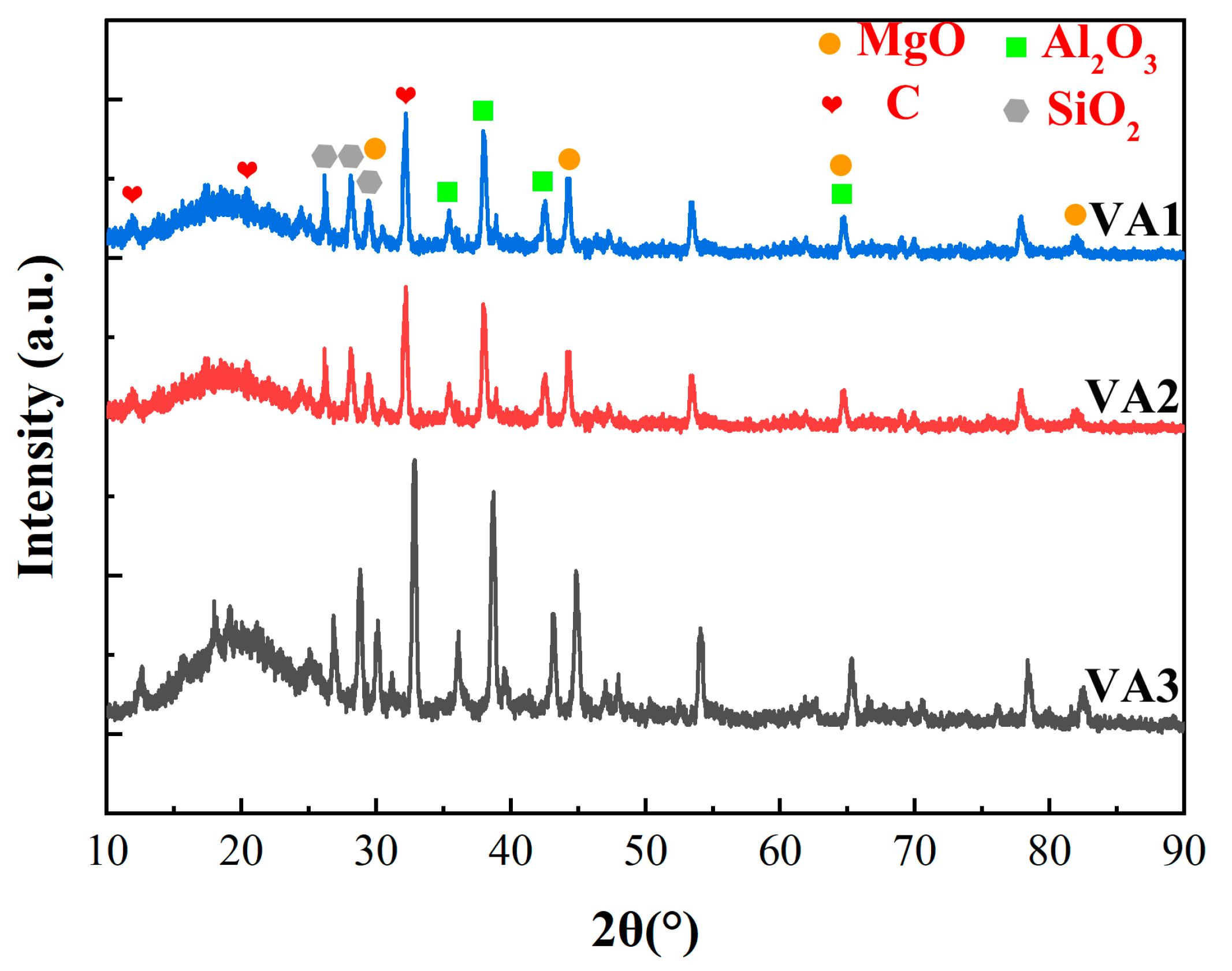
The XRD diffraction pattern analysis (
Figure 3) indicated that the three coatings were primarily composed of amorphous graphene, α-Al
2O
3, SiO
2, and MgO phases. Since the diffraction peak positions and relative intensities of the three coatings were highly consistent, this demonstrated their excellent uniformity in surface chemical composition, further confirming the stability and reproducibility of the coating preparation process. Additionally, the epoxy resin exhibited a typical amorphous halo (broadened diffuse peak without sharp diffraction peaks) in the range of 2θ = 15°–30° (Cu Kα radiation, λ = 1.5418 Å), with its main peak located near ~20°. The exact peak position is influenced by factors such as the type of curing agent, filler content, and crosslinking density.
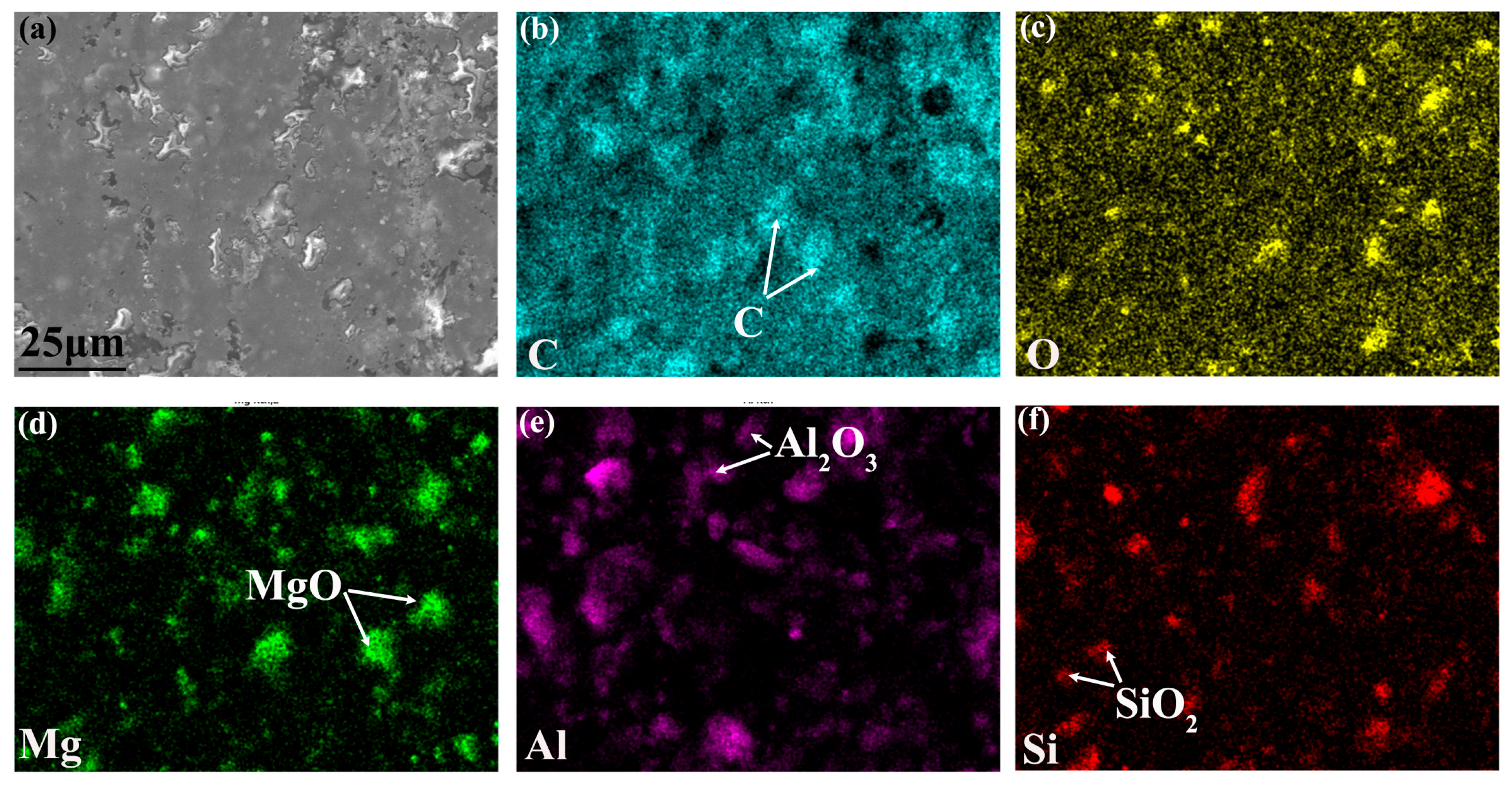
Combined with the SEM–EDS elemental mapping results (
Figure 4), the multiphase distribution characteristics of the coatings can be clearly identified: in the high-magnification SEM images, the bright white regions with significant contrast differences were confirmed to have higher graphene content, corresponding to the graphene sheet structure; the white regions were identified as the MgO-Al
2O
3-SiO
2 multicomponent ceramic phase; while the gray continuous phase mainly consisted of C (68.4 at.%) and O (31.6 at.%), matching the stoichiometric ratio of the epoxy resin matrix. The ceramic particles and graphene (particle size distribution: 5–15 μm) were uniformly dispersed in the epoxy resin matrix around the ceramic phase, with no observed interfacial defects such as microcracks or pores.
The enlarged SEM–EDS surface morphology of VA2 coating before hydrogen charging is shown in
Figure 5, further revealing that graphene mediated the formation of fully dense interfacial architectures with ceramic particles. The inherent flexibility of graphene permits conformal wrapping around ceramic particulates. During the sintering process, this adaptability facilitates the formation of conformal interfaces at the graphene/ceramic boundaries, while simultaneously establishing a percolating conductive network with an improved conductive network architecture [
16].
The interfacial bonding performance between the coating and substrate was systematically evaluated using the scratch test method (
Figure 6). A Rockwell C-type diamond indenter (120° cone angle, 200 μm tip radius) was employed to perform scratching on the coating surface at a loading rate of 10 N/min, while acoustic emission signals and frictional force variations were simultaneously monitored (
Figure 6a).
The test results revealed that the critical loads (Lc) for VA1 and VA3 coatings were 0.689 ± 0.015 N and 0.7001 ± 0.012 N, respectively (
Figure 6b). Despite their thickness differences (296 μm vs. 317 μm), no significant variation in interfacial bonding strength was observed, indicating that coating thickness has minimal influence on adhesion performance. This consistency is primarily attributed to the uniformity of the preparation process.
Acoustic emission signal analysis demonstrated that when the load reached the critical value, the initiation and propagation of microcracks within the coating led to elastic wave release, with a sudden amplitude increase (>45 dB) corresponding to the initial coating failure. Combined with SEM observations of scratch morphology (
Figure 6c), the coating peeling spot can be recognized where the non-conductive ceramic is exposed. As the scratching force increases, the accumulation of non-conductive ceramic particles leads to a rise in the white phase. Meanwhile, the failure modes were found to primarily consist of radial cracks at the coating edges and localized spallation in the central region. This suggests that the coatings possess moderate toughness, enabling stress dissipation through microcracking and avoiding brittle fracture.
In practical applications, coating adhesion is crucial for functionality. However, ceramic particles and graphene inherently lack adhesive properties. Therefore, optimizing molecular interfacial structures and interactions is essential to enhance the overall adhesion of the composite material, ensuring it meets the performance requirements for real-world applications.
Systematic measurement of residual hydrogen content after four-day hydrogen charging (
Figure 7) was conducted using gas chromatography, with two parallel samples taken from both middle and lower sections of each specimen. The results revealed distinct hydrogen barrier performance among coatings with different thicknesses: The VA3 coating demonstrated optimal barrier effect with an average hydrogen content of merely 0.28 ± 0.09 ppm, while VA1 and VA2 coatings showed 0.68 ± 0.11 ppm and 0.32 ± 0.07 ppm respectively. In contrast, the uncoated X60 pipeline steel substrate exhibited significantly higher hydrogen content (2.49 ± 0.24 ppm)—nearly nine times greater than that of the best-performing VA3 coating.
During hydrogen measurement, polymer coatings were first removed by mechanical grinding to avoid thermal decomposition interference before determining the solid-solution hydrogen content in the steel substrate, though this process might lead to partial escape of diffusible hydrogen. Electrochemical hydrogen permeation tests revealed dual diffusion pathways for H⁺ generated in the electrolytic cell under voltage/current: partial hydrogen was absorbed and trapped by coatings while the remainder penetrated into the steel substrate. The hydrogen barrier mechanisms primarily involved: (1) prolonging hydrogen diffusion paths to retard permeation rate; (2) delaying hydrogen arrival time at the substrate. Experimental data confirmed VA3 coating’s superior barrier performance (0.28 ± 0.09 ppm average substrate hydrogen content), representing 79% reduction compared to layered mGO coating (1.34 ppm) [
9].
Ceramic coatings have been extensively investigated for hydrogen barrier applications. However, their widespread adoption is hindered by several inherent limitations, including significant thermal expansion coefficient mismatches with metallic substrates, inherent brittleness, the presence of microcracks, and inadequate interfacial adhesion. These factors collectively compromise their hydrogen barrier efficacy [
17,
18,
19,
20,
21]. In this context, recent studies have demonstrated that incorporating 0.5 wt% graphene oxide into Al
2O
3 ceramic coatings enhances their fracture toughness by approximately 40% compared to monolithic Al
2O
3 coatings [
22]. Meanwhile, epoxy resins—representative high-performance thermosetting polymers—have emerged as promising alternatives due to their tailored molecular architecture. The polar hydroxyl and ether groups in their molecular chains facilitate robust chemical bonding with metal substrates, ensuring exceptional adhesion. Moreover, their ultralow curing shrinkage (<2%) minimizes residual stresses and crack formation, thereby maintaining dimensional stability—a critical attribute for industrial protective coatings.
Based on this, further performance optimization can be achieved through the development of composite systems in ceramic, a universally applicable strategy in polymer-based coatings. Research indicates [
23,
24] that the hydrogen barrier performance of such composites is governed by two key parameters: the tortuosity of permeation pathways dictated by filler dispersion and alignment; and the reduction in free volume controlled by interfacial interactions. Notably, systems combining rigid polymer matrices with lamellar nanofillers (e.g., ceramic or graphene) exhibit synergistic effects: they not only restrict polymer chain mobility to reduce free volume but also create multiscale barrier architectures that drastically prolong gas diffusion paths, yielding superior barrier properties [
25]. This ceramic/graphene-reinforcement paradigm offers a versatile framework for designing advanced protective coatings. Building upon this foundation, the VA-series composite coatings exhibit outstanding hydrogen barrier properties coupled with robust interfacial adhesion.
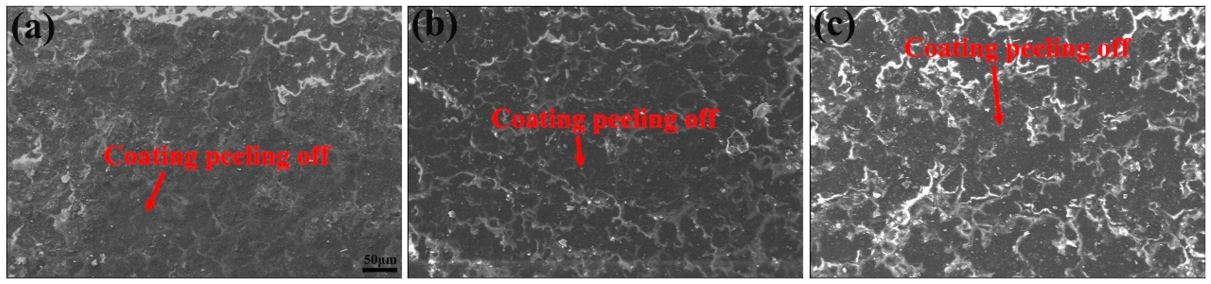
Analysis of coating surface morphology after four-day hydrogen permeation (
Figure 8) revealed varying degrees of surface spallation across all samples, with VA1 coating exhibiting the most severe delamination (
Figure 8c). SEM–EDS analysis (
Figure 9) further demonstrated that the spalled regions primarily consisted of Al
2O
3/SiO
2 ceramic particles, with visible porous structures observed at detachment sites. The peeling regions mostly exhibit intergranular fracture characteristics, indicating that optimizing the interfacial bonding strength between ceramic particles and the resin matrix will be a key direction for improving the hydrogen resistance of the coating.
Table 1 compares the changes in surface composition of the three coatings before and after electrochemical hydrogen charging. It can be observed that the surface chemical compositions of the three coatings were similar before hydrogen charging (C: 69.92%–70.7%, O: 15.02%–16.85%, Al: 7.09%–8.66%, Mg: 1.59%–2.23%, Si: 1.96–2.23 wt.%). However, after hydrogen charging, the surface composition of the coatings changed significantly: the carbon content increased in all cases, while the oxygen content remained relatively stable. In contrast, the contents of the ceramic-phase elements Mg, Al, and Si decreased substantially. Specifically, for the VA1 coating, the aluminum content dropped sharply from 8.66 to 1.75 wt.%, a reduction of 79.8%. For the VA3 coating, the Al content decreased from 7.09 to 2.43 wt.%, a reduction of 65.7%. This directly confirms the preferential detachment of Al
2O
3 particles in a hydrogen environment, indicating that, regardless of coating thickness, ceramic particles underwent surface spallation. Furthermore, this phenomenon also suggests that increasing the coating thickness can hinder further hydrogen penetration. Similarly, the decreases in Mg and Si contents further support this observation, demonstrating that MgO and SiO₂ particles also participate in hydrogen-induced damage. These changes collectively prove that hydrogen penetration primarily disrupts the bonding at the ceramic–resin interface, leading to the selective spallation of reinforcing phases (Al
2O
3 > SiO
2 > MgO) and ultimately causing carbon enrichment on the coating surface. This element-selective migration phenomenon can be explained by the hydrogen-material interaction mechanism: the plasticizing effect of hydrogen on the epoxy resin’s cross-linked network weakens interfacial bonding strength. Notably, the VA1 coating exhibited the highest Al loss rate (62.3%), which aligns well with its most severe surface spallation morphology.
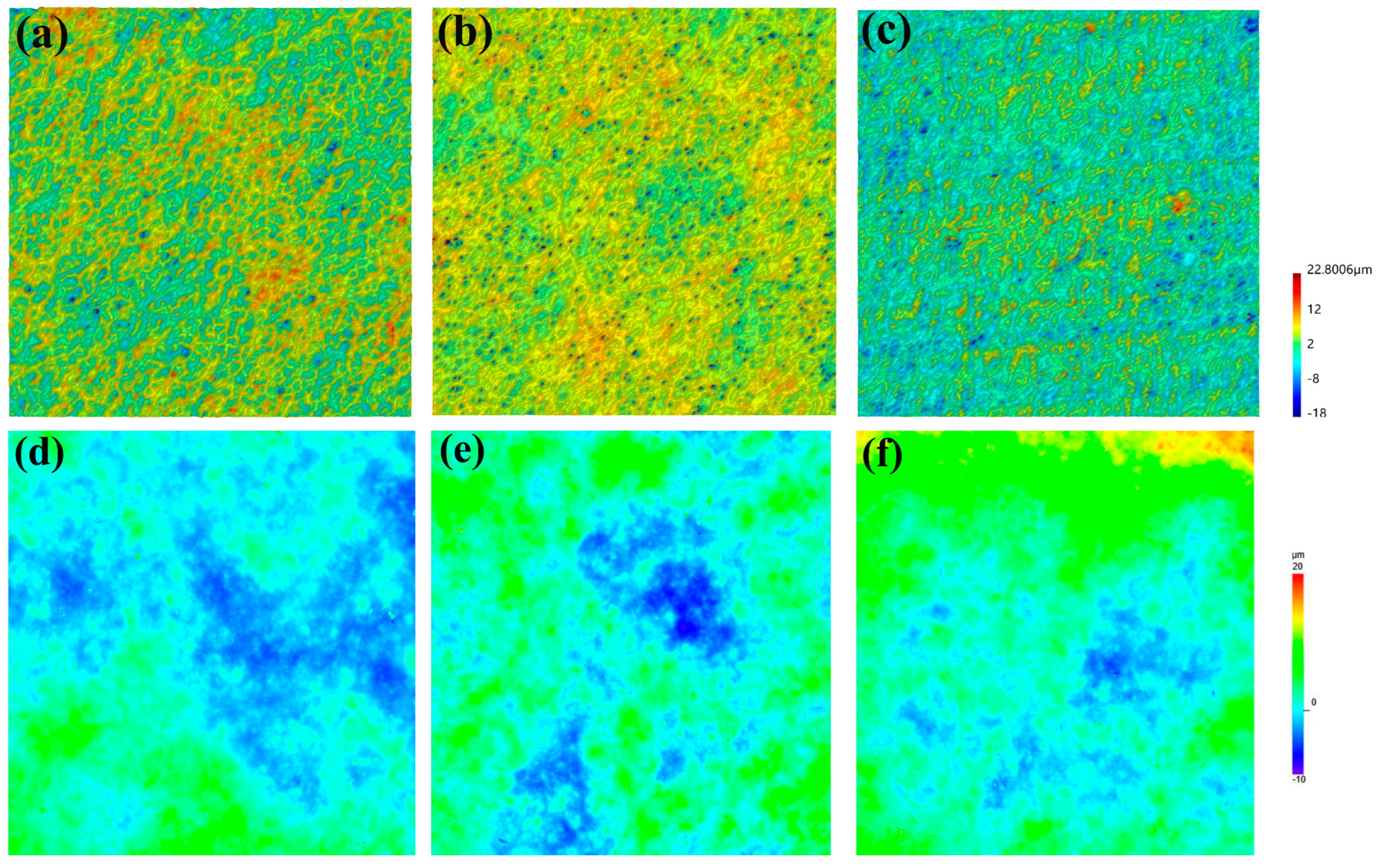
Meanwhile, 3D topographic characterization (
Figure 10) revealed a correlation between coating surface roughness amplitude before and after hydrogen charging. The VA1 coating demonstrated the most pronounced height variation (40.8 ± 2.3 μm) after hydrogen charging, correlating with its highest hydrogen permeation level (0.68 ± 0.11 ppm). Notably, the severe peeling of the VA1 coating exhibited a strong correlation with its relatively high hydrogen content (
Figure 7). In contrast, the optimal-performing VA3 coating exhibited the minimal height variation (28.8 ± 1.7 μm), aligning with its lowest hydrogen content (0.28 ± 0.09 ppm). For comparison, the three coatings exhibited similar initial height variations of approximately 30 μm prior to hydrogen charging, which further confirms coating peeling during the hydrogen charging process. The underlying failure process can be concluded: stress concentration occurs at the ceramic particle/epoxy resin interface during hydrogen permeation, leading to interfacial bonding failure; hydrogen atoms accumulate on the surface of ceramic particles and form hydrogen molecules, generating localized high pressure; the epoxy resin matrix undergoes plasticization in a hydrogen environment, and the difference in thermal expansion coefficients between the resin (resin ≈ 60 × 10
−6 K
−1) and ceramic particles (ceramic ≈ 8 × 10
−6 K
−1) exacerbates interfacial delamination.
4. Discussion
For the composite coatings, ceramic particles provide physical blocking by extending gas permeation paths, while the epoxy matrix offers exceptional interfacial bonding and deformation coordination capabilities. The incorporation of Al
2O
3/SiO
2 ceramic networks effectively reduces the coating porosity to below 0.5% by sealing micro-pores and grain boundary defects in the epoxy matrix, thereby establishing an efficient physical barrier system. The ceramic—graphene—resin ternary interface creates interfacial polarization effects, demonstrating significant repulsion towards nonpolar H
2 molecules. Meanwhile, the (100) crystal plane of MgO forms surface adsorption sites with hydrogen atoms (binding energy 0.85 eV), further reducing hydrogen permeability. This chemisorption effect decreases hydrogen permeation compared to pure epoxy systems [
26,
27]. The crystalline lattice structure of pristine graphene exhibits interatomic spacing (0.246 nm) substantially smaller than the kinetic diameter of hydrogen molecules (0.289 nm), thereby creating an impermeable physical barrier through molecular sieving effects. Meanwhile, graphene offers high-surface-area adsorption sites without the pass through of H
2. Thereafter, incorporating graphene hydrogen barrier layers can further reduce hydrogen permeation, while increasing ceramic content may lower the hydrogen diffusion rate through the resin matrix.
Under electrochemical hydrogen charging conditions, resin-based ceramic composite coatings may experience reduced adhesion or even peeling due to hydrogen permeation and interfacial interactions. The failure mechanism involves hydrogen diffusion, interfacial chemical changes, and stress coupling effects. The electrochemical reaction (2H+ + 2e− → H2) generates hydrogen gas, and hydrogen molecules or atomic hydrogen (H) diffuse through the free volume or micropores of the resin matrix.
Although hydrogen diffusion in ceramic particles is extremely slow [
17,
18], it may preferentially permeate along the resin/ceramic interface. Hydrogen accumulates and recombines into H
2 at the resin/ceramic interface, forming localized high pressure. When this hydrogen pressure exceeds the coating’s bonding strength, it leads to interfacial delamination, blistering, or peeling of the coating. In ceramic coatings, the high dissociation energy of Al-O and Si-O bonds [
28,
29,
30,
31] makes atomic hydrogen diffusion difficult, favoring molecular diffusion. According to the previous studies, the composite coating can be impermeable for gas like hydrogen or helium with a graphene film layer [
17]. In here, the graphene/ceramic of the composite coating is considered as a smaller impermeable film. The deuterium atoms cannot pass the graphene and ceramic nanosheets and it will diffuse along the interface of the graphene nanosheets with ceramic, resulting the peeling of ceramics.
In addition, for the vast majority of materials, the thickness of the coating affects the hydrogen atom penetration path. If the coating is thick enough, hydrogen must pass through more of the coating, and the penetration rate decreases. From this perspective, the thicker the coating, the more influential the hydrogen barrier. An excessively thick coating can generate stress concentrations, leading to easier rupture of the coating under hydrogen pressure; it is also more prone to thermal stresses at high temperatures, which affects the structural integrity of the coating and, thus, its hydrogen-blocking performance. For example, Li et al. [
32] found that Er
2O
3 coatings at 200 μm can reduce the hydrogen permeability by ten. However, when the coating thickness is more significant than 200 μm, the hydrogen barrier decreases with the coating thickness because the grain becomes rough with the increase of coating thickness, the internal stress increases, and the coating performance is damaged, thus reducing the hydrogen permeation barrier.
For single ceramic coating systems, the delamination tendency increases markedly with coating thickness; whereas for composite coating systems, greater thickness can conversely enhance hydrogen barrier performance. Within the composite coating architecture, even if partial delamination occurs in the surface ceramic layer, the underlying structure retains intact ceramic particle arrangements, thereby preserving effective hydrogen-blocking functionality. Furthermore, hydrogen permeability exhibits an inverse square relationship with coating thickness (P∝1/d
2) [
33]. The VA3 coating demonstrates significant suppression of hydrogen diffusion kinetics when exceeding a critical thickness of 300 μm. As summarized in
Figure 11, the hydrogen diffusion resistance shows a strong coating-thickness dependence, where VA3 requires hydrogen to traverse a significantly longer diffusion path compared to VA1. This extended diffusion pathway directly contributes to the enhanced barrier performance observed in thicker coatings.
This study reveals that delamination primarily propagates along the ceramic particle/resin interface, suggesting the following strategies to enhance coating performance: surface modification of ceramic particles using silane coupling agents; introduction of flexible interlayers (polyurethane) to mitigate stress concentration; and optimization of curing processes to minimize interfacial defects. These findings provide theoretical guidance and technical pathways for designing highly reliable hydrogen-resistant coatings.


