Abstract
With the growing requirements for multi-particle process simulation, improving computational accuracy, efficiency, and scalability has become a critical challenge. This study generally focused on comprehensive analyses of existing numerical methods for simulating particle–substrate interactions in gas–thermal spraying (including gas–dynamic spraying processes), covering both single-particle and multi-particle models to develop practical recommendations for the optimization of modern coating spraying processes. First of all, this paper systematically analyzes the key limitations of current approaches, including their inability to handle high deformations effectively or high computational complexity and their insufficient accuracy in dynamic scenarios. A comparative evaluation of four numerical methods (Lagrangian, Arbitrary Lagrangian–Eulerian (ALE), Coupled Eulerian–Lagrangian (CEL), and Smoothed Particle Hydrodynamics (SPH)) revealed their strengths and weaknesses in modeling of real gas–thermal spraying processes. Furthermore, this study identifies the limitations of the widely used Johnson–Cook (JC) constitutive model under extreme conditions. The authors considered the Zerilli–Armstrong (ZA), Mechanical Threshold Stress (MTS), and Preston–Tonks–Wallace (PTW) models as more realistic alternatives to the Jonson–Cook model. Finally, comparative analyses of theoretical and realistic deformation and defect-generation processes in gas–thermal coatings emphasize the critical need for fundamental changes in the simulation strategy for modern gas–thermal spraying processes.
Keywords:
particle impact simulation; spraying technology; protective coatings; Lagrangian; ALE; CEL; SPH 1. Introduction
In modern coating spraying processes, numerical simulations of particle impact are typically carried out using the finite element method, which simulates the plastic deformation, stress distribution, and temperature field distribution between particles and substrates during particle impact using Finite Element Modeling (FEM)/Computational Fluid Dynamics (CFD)/Molecular Dynamics (MD) platforms such as Abaqus/Explicit, LS-DYNA, COMSOL, ANSYS Fluent, and LAMMPS [1,2]. Modeling of gas–thermal spraying deposition processes is a challenging problem because it involves modeling of multiple-particle contact, bonding and debonding processes, plastic deformation of a single particle, etc. The traditional finite element method (FEM) can be successfully applied to the simulation of high-speed impact processes. FEM provides a simulation by constructing a mesh model that dynamically adapts to material deformation [3]. A smaller mesh size ensures more accurate simulation results. Furthermore, this method provides a high calculation speed and can simulate all the changes in temperature and residual stress between the substrate and particle interface [4,5]. However, due to high computational costs and complex modeling requirements to ensure accurate results, many studies have focused on single spherical particle impact models [6,7].
Several numerical methods have been widely employed to simulate particle impacts in gas–thermal spraying (including gas–dynamic spraying processes), including FEM-based approaches such as Lagrangian, ALE, and CEL methods, as well as meshless methods like SPH [8,9]. Each of these approaches has demonstrated unique strengths: Lagrangian FEM provides computational efficiency for low to medium velocity impacts [10], ALE improves numerical stability under severe deformation [11], CEL allows modeling of coupled solid–fluid interactions [12], and SPH captures extreme plastic flow and jetting phenomena [13]. However, all these methods also exhibit limitations. For instance, Lagrangian FEM suffers from mesh distortion and SPH has a high computational cost, and none of the methods systematically account for particle size distributions, temperature gradients, or stochastic multi-particle deposition effects [14,15].
A major limitation of current research is the lack of a systematic, quantitative framework for evaluating the applicability of these simulation methods. Most comparative studies in the literature have been qualitative, focusing on descriptive differences rather than on parameter-based performance metrics. Moreover, the majority of existing work emphasizes single-particle impacts, whereas practical gas–thermal spraying processes (including gas–dynamic spraying processes) involve complex multi-particle interactions that significantly influence coating microstructure, porosity, and bonding. Without a consistent evaluation framework, it is difficult to determine which method is most suitable under specific processing conditions, and there is limited transferability of simulation results to industrial applications.
This study systematically evaluates the applicability of existing simulation methods for gas–thermal spraying (including gas–dynamic spraying processes) under both single- and multi-particle conditions. A quantitative framework is proposed that considers key process parameters such as particle velocity, size distribution, surface temperature, and particle–substrate property mismatch. By incorporating these factors into the analysis of plastic deformation and bonding behavior, the framework enables a more reliable assessment of model performance and supports the selection of suitable simulation approaches.
2. Single-Particle Simulation
Taking Abaqus/Explicit as an example, the influence of particles on the substrate can be modeled using explicit finite element (FE) models and Lagrangian formulas. Particle and substrate material property parameters typically include density, thermal conductivity, Poisson’s ratio, specific heat, shear modulus, JC parameters, etc. Among various constitutive models for predicting material deformation behavior under high strain rates, the JC model is one of the most widely used in cold-spray computational studies due to its simple formulation and extensive availability of parameter data for various metallic materials [16,17].
The Step Module is usually set to use either the Dynamic, Explicit or Dynamic, Explicit step, and the step time is also set.
In the contact interaction module, the tangential friction coefficient between particles and substrate is typically defined within a range of 0.2 to 0.5 [18,19]. For high-velocity impact conditions, global deformation is less sensitive to the friction coefficient than to other factors, such as impact velocity and material properties. Consequently, simulation results demonstrate significant robustness against its variation, allowing the selection of a value from the common range as a sufficient baseline for most studies [10]. This demonstrates that the friction coefficient is not a critical parameter for predicting global deformation in high-velocity impact.
Furthermore, the maximum equivalent plastic strain (PEEQ) and temperature rise at the interface exhibit minimal variations across these cases. This finding suggests that the friction coefficient has a negligible influence on both the particle deformation patterns and interfacial thermo-mechanical responses in such scenarios.
In the Load Module, it is necessary to constrain the degrees of freedom between the particles and the substrate, and define the initial velocity, temperature, and substrate temperature of the particles. In the mesh partitioning section, the ratio of mesh size to substrate size is less than 1/50 to achieve a convergent result.
The Lagrangian method has some drawbacks, especially when the particle velocity is high: it may cause severe deformation of the mesh, thereby making the calculation unable to continue. In addition, when the particle velocity is less than the critical deposition velocity of the substrate, the particles cannot bind to the substrate surface, resulting in insufficient interaction with the substrate and causing rebound phenomenon. This phenomenon will affect the accuracy and convergence of the model in areas of strong deformation.
These limitations of the Lagrangian method motivate the adoption of alternative approaches, such as the Eulerian, ALE, and SPH methods. The ALE method, in particular, overcomes the issue of mesh distortion by dynamically remeshing the computational grid during the simulation, thereby allowing the calculation to continue stably even under extreme deformations. For example, Li et al. [10] studied the particle deformation behavior of Cu particles in cold spraying using the Ansys LS-DYNA program and the Lagrangian and ALE methods. Under identical simulation settings, both the ALE and Lagrangian methods produced consistent results when analyzing how impact velocities and compression ratios affect particle deformation. Nevertheless, when applying the ALE method to model the variations in the maximum effective plastic strain during the impact process at different impact velocities (300–800 m/s), the curve of maximum effective plastic strain over time appeared to be more gradual, whereas the curve calculated using the Lagrangian method appeared to be more abrupt, as illustrated in Figure 1. This discrepancy may be attributed to the deformation of the Lagrangian method unit mesh division.
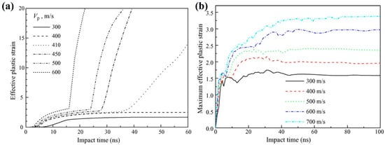
Figure 1.
Simulated temporal development of maximum effective plastic strain of particle material under different particle velocities modeled by (a) the Lagrangian method and (b) the ALE method [10].
In the context of the Euler method, the mesh remains static and cannot adapt to the changes in the shape of the object. This can make it less intuitive and less effective compared to the Lagrange and ALE methods when dealing with solid objects and complex deformation problems. Thus, Meng et al. [20] developed a 2D single-particle Euler FEA (Finite Element Analysis) model to investigate the effects of mesh spacing, substrate size, material failure, initial temperature, particle velocity, and total simulation time on residual stresses in the cold-spray process. They found that mesh spacing, substrate size, and initial temperature strongly affect the distribution of residual stresses. For a Cu-particle–Cu-substrate case with a particle diameter of 30 µm, the recommended settings are a mesh spacing of 0.6 µm, a substrate domain of 2 mm × 2 mm, and a total simulation time of 200 ns. In addition, increasing the initial material temperature lowers the residual stress through thermal softening, with the effect more pronounced at lower particle velocities.
In the SPH method, each physical component in the model (e.g., metallic particles) is represented by SPH numerical particles. Field variables such as pressure and temperature are assigned to each SPH particle. As a result, the resolution of the model depends on the size of the SPH particles. Due to the implementation of explicit time integration, these field variables are updated at each time step, enabling the simulation of rapid dynamic problems involving substantial deformations, typical for gas–dynamic spraying processes. Once the process of evolution starts, there is no need for a mesh to simulate the problem. However, the initial distribution of particles is necessary to define the problem. Gnanasekaran et al. [21] used the SPH method and established boundary conditions using Monaghan type 2 particles to study the impact of copper particles of different sizes and angles. It was discovered that as the impact angle decreases, the highest temperature during contact actually rises, thereby increasing the likelihood of material melting. Nevertheless, reducing the angle can result in a rebound between the particles and the substrate, and particles that collide at an angle between 80° and 90° can effectively adhere to the substrate.
Obviously, these four numerical analysis approaches exhibit significant differences in their model configuration and simulation results, with the initial design of each method contributing to these disparities. Thus, Xie et al. [22] systematically demonstrated these distinctions through schematic representations of 2D axisymmetric models (applicable to Lagrangian and CEL methods) alongside 3D configurations (suitable for SPH and CEL approaches) (Figure 2).
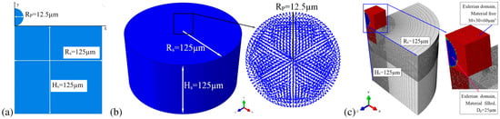
Figure 2.
Schematic representations of (a) the 2D axisymmetric model, (b) the 3D SPH model, and (c) the 3D CEL model [22].
A comparative study by Oyinbo et al. [23] effectively highlights the distinct deformation characteristics predicted by the four numerical methods under identical impact conditions. The simulation involved a 10 μm spherical Cu particle impacting a cylindrical Al substrate at an initial velocity of 500 m/s over a 60 ns duration. Their analysis of a single Cu particle impacting an Al substrate revealed that the Lagrangian method captures pronounced jetting but suffers from mesh distortion, while SPH shows deeper penetration with minimal jetting. The ALE method produces a smooth jet profile by mitigating mesh issues, and the CEL method, treating the particle in an Eulerian framework, yields a more uniform strain distribution. This comparison underscores how the fundamental formulation of each method dictates its representation of high-strain-rate phenomena. This comparison clearly reveals that the choice of numerical method directly influences the predicted impact morphology and strain distribution. Consequently, the choice of numerical method is a primary determinant of simulation outcome in impact modeling.
Therefore, single-particle simulation has become a fundamental and practical research tool wildly used in gas–thermal spraying (including gas–dynamic spraying processes). It effectively elucidates the core interaction mechanisms between particles and substrates during spraying while striking a balance between computational cost and physical fidelity. Nevertheless, this approach is inherently limited to idealized conditions and operates with artificially isolated systems. It cannot account for phenomena characteristic of actual spray deposition, such as inter-particle collisions, collective thermal effects, stochastic process variations, or the progressive build-up of coatings. Therefore, a systematic comparison of the numerical methods employed in such simulations is essential for their practical applicability in the industrial sector.
Table 1 compiles representative case studies, compares the predictive outcomes of each method under key parameters, and synthesizes their applicability and limitations.

Table 1.
General analyses of simulation parameters for single-particle interaction: typical examples of spraying processes.
Thus, a clear comparison of the fundamental trade-offs between methods is essential for selecting the most suitable one for a given single-particle simulation. Accordingly, a systematic comparison of the Lagrangian, ALE, CEL, and SPH methods are assessed in the “Conclusions and recommendations” section, focusing on numerical stability, predictive fidelity for interfacial bonding, and computational cost.
3. Multi-Particle Simulation
Despite promising technological advantages, the study of the simulation of multi-particle gas–thermal spraying (including gas–dynamic spraying processes) is still not comprehensive, particularly regarding the effects of subsequent particle impact after a single particle impacts the substrate. Additionally, the impact of particles at different angles and initial velocities on the substrate, as well as interactions between particles, remains not well explained or detailed. Since, in the context of multi-particle spraying, the influence of temperature and deformation on the physical properties of the initial particles, such as density, thermal conductivity, and Young’s modulus, needs to be considered. These factors can also significantly affect the results of subsequent particle collisions. Therefore, a systematic evaluation and comparison of existing multi-particle simulation methods—focusing on their features, limitations, and applicability—is essential to guide the future development of new engineering tools for optimizing coating deposition technologies.
3.1. CEL Method
The advantages of this method include calculating the Euler volume fraction of each element, tracking material flow through the mesh over time, and maintaining an unchanged mesh in the Euler domain. These capabilities collectively solve the severe mesh deformation problem caused by high-speed impact. Thus, Xie et al. [29] compared the CEL and ALE methods by studying the effect of aluminum particles on aluminum substrates. They concluded that CEL cannot numerically study particle deformation because it only reports the average value of each variable for Euler particles. However, CEL can be recommended for simulation of spraying impact processes as the most accurate method for analyzing substrate deformation and predicting the porosity level of manufactured samples.
Yang et al. [30] employed the CEL method to establish a multi-particle impact model (Figure 3). Their simulations demonstrated that the maximum compressive residual stress in the substrate decreases with an increasing number of impacting particles. Furthermore, under an equal particle count, smaller particles were found to generate greater compressive residual stress. This finding underscores the critical importance of multi-particle simulations for accurately predicting the realistic stress fields generated in thermal spray processes.
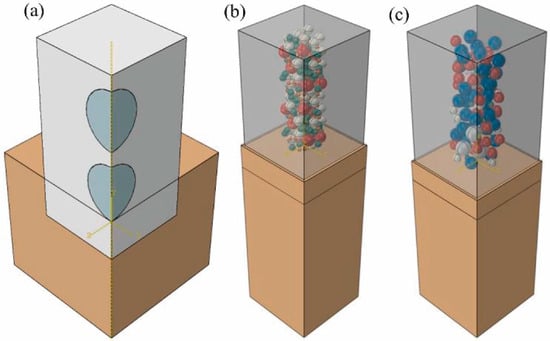
Figure 3.
CEL multi-particle model: (a) continuous model, (b) random small-particle-size model, (c) random big-particle-size model [30].
Furthermore, Song et al. [31] also used the same method and simulated the multi-particle impact process of Ti–6Al–4V powder cold spraying onto a Ti–6Al–4V substrate using the CEL framework. At the same time, Python scripts were used to model the particles to ensure that their positions were randomly assigned in the Euler domain and that their velocities and temperatures were distributed based on their diameters. This would have made the calculation of porosity after sedimentation more accurate. In addition, by refining the mesh, it was found that when the mesh size was reduced to 2 μm (1/60 of the side length of the Euler domain), the porosity (3.9%) obtained was close to that of the mesh size of 1.5 μm (1/80 of the side length of the Euler domain; porosity: 3.6%), but the calculation time was reduced from 1142 h to 292 h. To more intuitively illustrate the CEL modeling strategy for cold-spray multi-particle deposition and its capability of representing the porosity and temperature fields, a typical CEL multi-particle model together with the key simulation results obtained by Tan et al. [32] is shown in Figure 4.
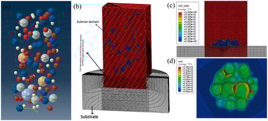
Figure 4.
CEL multi-particle deposition model and simulation results: (a) multi-particle model; (b) Eulerian domain and substrate; (c) effective volume fraction (EVF) void distribution; (d) temperature distribution [32].
Matteo Terrone et al. [33] employed the commercial software KSS to simulate the impact velocity and temperature of Cu-Ti mixed powder under varying pressures and temperatures. Their approach integrated Python scripts to implement a custom algorithm for assigning particle velocity and temperature fields. Mesh convergence analysis indicated that a mesh size of 2 μm optimally balances accuracy and computational cost—a finding consistent with Song [31]. Through simulations on Ti-Cu and Ti-Al blends with sacrificial material volume fractions of 30%, 40%, 50%, and 70%, and using a novel post-processing step to numerically remove the pore-forming material (simulating chemical etching), the study demonstrated that a sacrificial powder volume fraction of 40%–50% yields an optimal interconnected porous Ti structure.
Weiller et al. [34] used the CEL method to simulate aluminum and aluminum alloy 2017-T3 as particles and substrates, and studied the porosity of eight spherical particles after impact. The results indicate that porosity in multi-particle impact simulations was characterized using a subsequent convex hull method. Porosity rates from 2% to 6.5% were achieved, in the same order of magnitude as experimentally measured values.
The CEL method is also well-suited for simulating the deposition of composite coatings. This capability was demonstrated by Behera et al. [35], who modeled the co-deposition of hydroxyapatite (HA) ceramic and Cu-Zn metallic powders (Figure 5). Their simulations, employing Eulerian meshes for particles and Lagrangian meshes for the substrate, accurately captured the performance trends: from the poor deposition efficiency (~8%) and bonding strength (1.80 MPa) of pure HA to the significant improvements seen in Cu-Zn (22%, 28.5 MPa) and the optimal HA-Cu-Zn composite (27%, 33.7 MPa, 136.3 HV). The CEL simulations successfully replicated the experimental trend that the addition of the ductile metal phase drastically improved deposition efficiency and bonding strength compared to pure HA. This ability to identify the individual contributions of different materials within a complex interaction underscores CEL’s utility for composite coating design.
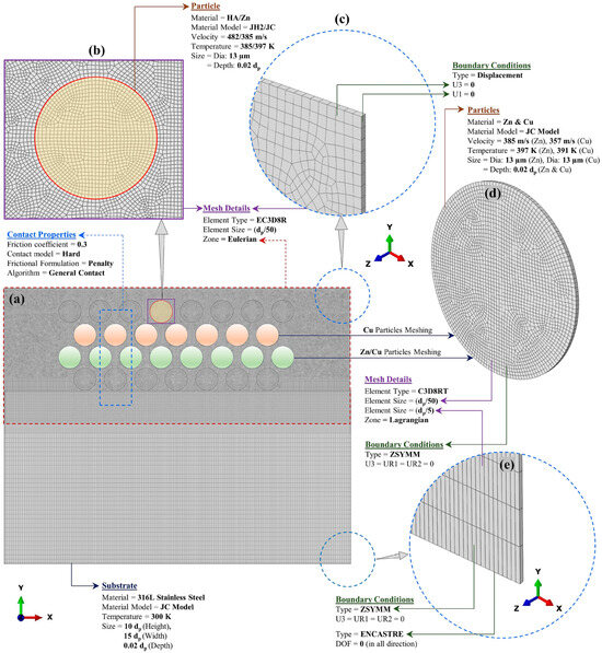
Figure 5.
(a–e) CEL model used in the multiple-particle impact simulation, with contact properties, mesh details, and boundary and initial conditions of particles and substrate [35].
Overall, the CEL method is a popular choice for multi-particle spraying simulations due to its robustness in handling large deformations. However, its application is accompanied by high computational costs and increased complexity in post-processing [36,37,38].
3.2. ALE Methods
So far, many studies have focused on the deposition of particles on smooth substrate surfaces during gas–thermal spraying. However, in practical applications, spray particles may affect the rough or even microchannel surface of the substrate. So, Wang et al. [39] studied the deposition characteristics of cold-sprayed Al particles on Mg alloy microchannel substrates using the ALE method, as shown in Figure 6, and investigated the deposition of single and multiple particles on the surface of microchannel substrates. The results indicate that when particles collide with the bottom of microchannels, the maximum contact area is maximized and the plastic deformation dissipation energy of the substrate is highest. Although the rebounding effect is minimal when particles collide with the edges of microchannels, particle deformation is similar to that affecting smooth surfaces when the particle diameter is too large or too small compared to the microchannel size. When the particle diameter approaches the width of the microchannel, both the particle and substrate deformation will intensify. When multiple particles collide with the microchannel substrate, the increase in particle velocity and initial material temperature can lead to porosity decrease.
Therefore, the ALE method demonstrates excellent mesh adaptability and is capable of accurately capturing asymmetric deformation, contact evolution, and subsequent particle tamping effects during high-velocity impacts. This makes it particularly well-suited for numerical simulations involving complex substrate geometries and multi-particle cooperative deposition.
Wang et al. [11] built a structured ALE model in LS-DYNA using one-point multi-material elements and the ALE_STRUCTURED_MESH_CONTROL option to simulate residual stresses in a single cold-spray microparticle and in up to four deposited layers at an impact velocity of 500 m/s. Their simulations, validated against X-ray diffraction and contour-method measurements, showed that σx is compressive at the coating surface and becomes tensile toward the interior, and that as the number of deposited layers increases, the maximum tensile zone shifts from the substrate to the coating. This demonstrates the capability of ALE to model multilayer cold-spray deposition and residual-stress evolution in a numerically stable manner.
Implementing another approach, Yu et al. [40] used Abaqus/Explicit to study the continuous impact of micrometer-sized solid metal particles on substrates (Al/Al, Cu/Cu, steel/steel, and nickel/nickel) using the ALE method. The particle radius was 12.5 μm, and a substrate size of 125 μm × 125 μm was used. The mesh size was 1 μm, and CAX4RT elements were used together with ALE analysis. The ALE remeshing technique was used for each increment, with a frequency of 10. The initial velocity of the particles was 400–800 m/s, the temperature was 673–1073 K, and the substrate temperature was room temperature. The simulations showed that good elliptical interfaces formed between aluminum particles, copper particles could be embedded into the substrate to form a bowl-shaped structure, and the first particle deposition of steel and nickel was severely compressed. Research has shown that due to the simplification of the geometric irregularity and surface state of actual powders by the model, the predicted idealized spray morphology deviates from experimental results. Therefore, this model is mainly suitable for general estimation of the degree of plastic deformation.
Thus, the ALE method offers enhanced accuracy in modeling multi-particle interactions [41]. Nevertheless, it involves considerable modeling complexity and may encounter mesh instability under extreme deformations—a limitation effectively addressed by mesh-free approaches such as SPH.
3.3. SPH Methods
Naturally, besides the collisions of individual particles, other factors such as collisions involving mixed particles should also be considered. Saleh et al. [42] implemented another approach for simulating the spraying process. The research team investigated the deposition of AA-6061-T6 particles on AA-6061-T6 substrates using LS-DYNA and the SPH method. Their simulations revealed significant plastic strain differences between the core and the periphery of the impacting particles, with the core exhibiting lower plastic deformation, while the periphery could experience much higher plastic deformation, potentially causing local temperatures to approach the melting point. One of the main results of this approach to multi-particle simulation is its ability to evaluate the degree of plastic deformation in gas–thermal spraying particles, providing insight into the thermal history and deformation mechanisms during deposition.
Zhang et al. [43] investigated the mechanism of pore formation in cold spraying using the SPH method, which included over 10 million discretization points and simulated approximately 200,000 powder particles for the first time. Pores can be divided into three types: macro-scale macropores, micro-scale micropores, and interfaces between different particles. The cross-sectional view obtained through numerical simulation in Figure 6 is used to explain how these pores are formed. In Figure 6a, large pores between particles exceeding the size of some smaller particles can be observed. The formation of these large pores is not related to particle interactions or bonding effects (such as rebounding or sliding). On the contrary, it is mainly caused by the uneven spatial distribution of particles before impacting the substrate. These results demonstrate that the SPH method is capable of accurately resolving both particle-scale interactions and macroscopic porosity evolution, offering a powerful tool for understanding and predicting defect formation in thermal spray processes.

Figure 6.
Cross-section views of the deposition track obtained by numerical simulations: (a) large pores in low-density regions, (b) small pores due to particle size difference, and (c) particle interfaces caused by the slipping and rebounding of particles [43].
Zhang et al. [44] developed an enhanced SPH method for large-scale simulation of cold-spray additive manufacturing (CSAM) with different powder sizes, morphologies, and distributions. Al-6061 powder with a diameter of 20–70 μm was used to generate powder using the Discrete Element Method (DEM). SPH particles were used to discretize each powder and model the CSAM process. Figure 7 shows the temperature field of powder deposition at different speeds during gas–dynamic spraying.
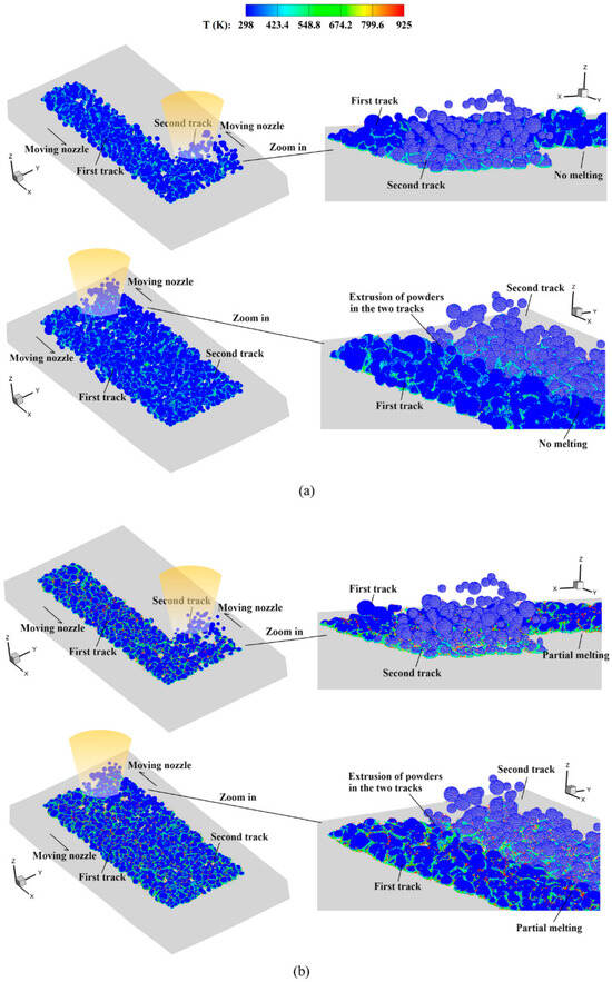
Figure 7.
Temperature field in the deposited powders during the multi-track multi-layer CS process: (a) Vd = 500 m/s and (b) Vd = 900 m/s [44].
The developed meshless method can simulate a large number of powders (up to tens of thousands), as well as approximately 10 million SPH particles. The adhesion and compression effects between two tracks at lower and higher impact velocities can be optimized to improve the powder impact velocity.
The SPH method excels in simulating large deformations and complex thermo-mechanical phenomena in spraying processes without mesh-related distortions [45,46]. Its main challenges include numerical stability, computational scalability, and accuracy in resolving short-range interactions [47].
Thus, multi-particle simulation more closely replicates the actual gas–thermal spraying process by accounting for inter-particle collisions and cumulative coating build-up. However, its increased complexity demands careful consideration of numerical method selection to balance predictive accuracy and computational cost.
Table 2 compiles representative studies to illustrate how different approaches handle this complexity, detailing the parameters and key outcomes for each case.
Table 2.
General analyses of simulation parameters for multi-particle interaction: typical examples of spraying processes.
Table 2.
General analyses of simulation parameters for multi-particle interaction: typical examples of spraying processes.
| Software and Methods | Particle and Substrate | Parameters | General Simulation Outcomes and Limitations | Ref. |
|---|---|---|---|---|
| Abaqus/Explicit (CEL) | Particles: Ti–6Al–4V alloy Substrate: Ti–6Al–4V alloy | Particle size: 25–45 µm Particle velocity: 750–800 m/s Particle temperature: 700–1100 K Substrate temperature: 373–473 K | This CEL model shows good agreement with experimental results for coating porosity prediction, with mesh convergence analysis identifying an optimal setup balancing accuracy and computational cost. Key limitations are the adiabatic assumption, neglect of heat transfer between particles and substrate, and the lack of modeling for particle–substrate or particle–particle bonding. | [31] |
| Abaqus/Explicit (ALE) | Particles: Cu/Al Substrate: Cu/Al | Particle size: 20 µm Substrate temperature: 473–873 K Particle velocity: 300–600 m/s | Simulation results confirm that impact velocity and substrate preheating temperature significantly influence the substrate’s temperature rise and equivalent plastic strain, aligning with practical observations. Limitations of the method include simplifying assumptions like adiabatic processes and incomplete capture of complex interactions between dissimilar materials. | [48] |
| Abaqus/Explicit (CEL) | Particles: Al Substrate: Cu | Particle size: 20 µm Particle velocity:700 m/s Temperature: 300 K | The model reveals the evolution of residual stress depth and magnitude with an increasing number of sequential particle impacts, from single to multiple particles, and confirms the significant effect of impact velocity on substrate temperature and plastic deformation. The applicability of the model is restricted by adiabatic process assumptions and neglect of complex interactions between particles and the substrate. | [30] |
| Abaqus/Explicit (Lagrangian/CEL/SPH/Eulerian Approach) | Particles: Cu Substrate: Cu | Temperature: 298 K Particle size: 10–50 µm Particle velocity: 300–1000 m/s | This comparative study reveals the inherent characteristics of different numerical methods: Lagrangian predictions are highly sensitive to mesh discretization. In contrast, the Eulerian and SPH methods are more suitable for simulating multi-particle impact processes due to their advantages in handling extreme deformations and representing interfacial bonding. | [49] |
| Abaqus/Explicit (CEL) Python MATLAB | Particles: WC-12Co; substrate: TC18 | Particle temperature: 1080–1480 K Substrate temperature: 300–900 K Particle velocity: 300–600 m/s | By incorporating a Voronoi polycrystalline method, the model introduces microstructural inhomogeneity in the substrate, simulates random deposition, and reveals high strain localization and pore formation within the coating. The model limitations include adiabatic assumptions, simplified spherical particle shapes, and neglected heat transfer effects, making it less suitable for modeling complex multi-phase interactions or continuous deposition. | [50] |
| Abaqus/Explicit ANSYS-Fluent 16.0 | Particles: Cp-Al, Al-2024, Al-6061, Al-7075 Size: 25 μm Substrate: Cp-Al, Al-2024, Al-6061, Al-7075 | Particle temperature: 573–873 K Substrate temperature: 573–873 K Particle velocity: 508–585 m/s | Simulations predict that increasing the stagnation temperature effectively enhances particle velocity and temperature, leading to improved coating thickness and interfacial bonding fraction, a trend consistent with experimental findings. The model simplifies multi-particle interactions and does not fully capture the complexities of inter-particle bonding or effects like layer-by-layer densification during continuous deposition. | [51] |
Therefore, the choice of method hinges on two key practical considerations: scalability to handle many particles and the computational cost required.
The “Conclusions and recommendations” section provides a comparative overview of the Lagrangian, ALE, CEL, and SPH methods for both single- and multi-particle simulations, guiding selection based on criteria such as robustness to mesh distortion, simulation scalability, and typical computational demands.
4. Critical Analysis and Comparative Assessment of Constitutive Models for Spraying Processes
4.1. JC Model
The previous section introduced the basic form and application of the JC model [10,52,53], but a large amount of research has shown that this model has significant shortcomings at high temperatures and high strain rates, such as the inability to accurately describe strain-rate sensitivity and thermal softening behavior. Therefore, scholars have proposed various improvement methods or used other models (such as MTS, ZA, PTW, etc.) for comparative verification. Table 3 summarizes the comparison of predictive performance between the JC model and improved models typical in the literature.
Table 3.
Applicability and limitations of the Johnson–Cook model across a broad range of strain rates and temperatures.
As shown in Table 3, the JC model has certain applicability under low to moderate strain-rate conditions, but the error significantly increases under high-temperature and high-strain-rate conditions. In contrast, the MTS model is more accurate in capturing stress levels, the ZA model performs better under thermal velocity coupling, and the PTW model shows advantages in the ultra-high-strain-rate range. Therefore, the following sections will further introduce these constitutive models with more complete physical foundations in order to select appropriate description methods for different application scenarios.
4.2. ZA Model
The Zerilli–Armstrong (ZA) model is grounded in the physics of thermally activated dislocation motion, which governs plastic deformation in metals [62]. Unlike Johnson–Cook, ZA explicitly links flow stress to the mechanisms by which dislocations overcome obstacles under different thermal and loading conditions [63]. It distinguishes between BCC and FCC metals: in BCC structures, dislocation motion is dominated by the athermal Peierls stress, resulting in a strong temperature and strain-rate dependence that is essentially independent of strain; whereas in FCC metals, dislocation intersections control the rate processes, making the activation area strain-dependent and coupling flow stress more strongly to evolving dislocation density [64]. In addition, the model incorporates grain-size strengthening, reflecting how microstructural barriers at grain boundaries influence plastic flow [65]. By capturing these fundamental mechanisms—thermal activation, crystal-structure-dependent rate control, and microstructural effects—the ZA model provides a physically consistent framework for describing temperature–strain-rate coupling and deformation behavior across a wide range of loading conditions, particularly for refractory metals and steels under high strain rates.
Recent studies have refined the ZA framework for modern alloy systems. Shokry et al. [66] modified the ZA formulation for titanium-based alloys, achieving predictive performance with average absolute relative errors below 4% in hot deformation tests. Lewis et al. [67] proposed a hybrid JC–ZA model for high-strength steels, combining the wide applicability of JC with the improved temperature–rate coupling of ZA, significantly reducing prediction errors. Earlier comparative work confirmed that ZA provides superior descriptions of BCC metals relative to JC across a wide strain-rate range [68]. These results highlight ZA’s advantage in intermediate-to-high-strain-rate applications, though additional softening terms are often required to capture microstructural mechanisms such as DRX or twinning.
4.3. MTS Model
The MTS model describes plastic deformation based on dislocation mechanics, separating the flow stress into a temperature-independent component, representing long-range barriers independent of temperature and strain rate, and a thermal component, reflecting dislocation motion over short-range obstacles controlled by temperature and strain rate. This partitioning captures how deformation transitions from temperature-independent resistance at low temperatures or high rates to thermally activated behavior at elevated temperatures. Each model parameter corresponds to a specific physical mechanism, giving MTS clear physical interpretability and strong predictive capability under extreme loading conditions [69,70].
Early evaluations demonstrated the superior predictive performance of MTS compared with empirical models. Banerjee [71] applied the MTS framework to multiple tempers of AISI 4340 steel, showing that it captured both stress–strain behavior and dynamic test results with greater fidelity than the JC model. Subsequent applications extended MTS to conditions relevant for high-strain processing. Follansbee [72] demonstrated its ability to represent the flow stress evolution in steels subjected to severe plastic deformation, while later review work consolidated applications across a wide range of alloys, confirming MTS validity under quasi-static to high-rate regimes [73].
Recent research has highlighted the adaptability of the MTS model for extreme conditions. Dowding and Schuh [74] showed that under strain rates above 106 s−1, metals exhibit anomalous thermal strengthening attributable to drag-controlled dislocation motion. Complementary studies by Tang and Hassani [75] used microprojectile impacts to directly quantify dislocation drag, providing mechanistic support for MTS extrapolation into ultra-high-strain-rate regimes. Together, these findings confirm that MTS offers a robust balance between physical fidelity and predictive versatility, although calibration requires extensive datasets and remains computationally demanding compared to empirical models.
4.4. PTW Model
The PTW model is a physically based constitutive law designed for extreme strain rates (~103–1011 s−1). It captures the fundamental transition in dislocation motion from thermally activated glide at lower rates to drag-controlled dynamics at very high rates, where lattice drag governs resistance rather than thermal barriers. This enables PTW to accurately describe deformation across a wide range of loading conditions, including impact and shock regimes, while preserving clear links to the underlying dislocation physics [76].
Recent advances have strengthened PTW’s role in high-rate applications. Nguyen et al. [55] calibrated PTW for β-Sn using combined quasi-static, SHPB, and Taylor cylinder tests, achieving accurate reproduction of deformation modes up to 105 s−1. Abigail [77] further introduced uncertainty quantification methods for PTW parameter identification, offering statistically rigorous confidence intervals for simulations. Earlier hypervelocity impact studies also validated PTW against crater morphologies at strain rates approaching 1011 s−1 [54]. Collectively, these contributions confirm PTW as the most appropriate model for applications involving ultra-high strain rates, including hypervelocity impact and cold-spray processes.
In summary, the four mainstream constitutive models—JC, ZA, MTS, and PTW—are each designed for simulating spraying processes within distinct strain-rate and temperature modes. The selection of a constitutive model must be strictly aligned with the strain-rate and temperature window of the intended simulation, as no universal optimum exists. To support researchers and engineers in making this choice, section “Conclusions and recommendations” provides a systematic comparison of these four models, summarizing their applicable strain-rate and temperature ranges, physical foundations, calibration data needs, and characteristic performance.
5. From Idealized Models to Realistic Deposition Mechanisms
In most previously analyzed simulations, the substrate and deposited coating layers are typically represented as a smooth, clean, and generally uniform surface. This approach is basic for a wide range of process deposition simulations because of the significant simplification of the deposition process description. However, in reality, any gas–thermal spraying (including gas–dynamic spraying processes) is critically characterized by significant substrate/coating surface-layer fluctuations, including extremely high roughness and surface irregularities and the presence of oxide layers, brittle inclusions, and machining defects, as well as the formation of internal cavities, debonding zones, cracks, and fractures, all of which significantly impact the deformation and bonding of the particles.
Therefore, systematical analyses and formalization of the critical factors are the most important stages for the development and implementation of next-generation tools for simulations of a wide range of gas–thermal spraying processes (including gas–dynamic spraying processes).
As ensured by critical analyses of practical results, one of the most important influencing factors typically not formalized in computer simulations is the occurrence of random surface irregularities, unpredictable deformations, and surface defects in specific zones.
Thus, Figure 8a visually highlights the scale and prominence of the material jetting zone (outlined) surrounding an embedded particle. Figure 8b, as well as numerous other practical investigation results, illustrate that a Critical Jetting Behavior zone (CJB zone) with a randomly changed complex of geometrical and physical parameters can cover a surface with an area reaching up to 70%–120% of the initial particle cross-section area (especially for ductile materials). This CJB zone introduces a substantial systematic error in integrated impact simulation results. Moreover, the CJB zone, considered uncountable, finally can be source of the point or group defects resulting in a significant decrease in the coating operational characteristics. This fact should be taken into account using an additional module for the estimation of CJB zone defect characteristics and special-zone surface-layer property recalculation for every cycle of the spraying process.
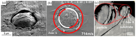
Figure 8.
Jetting zone (zone A) and microstructural irregularities (including multi-layer shearing/delamination—zone B) effects at cold-sprayed interfaces: (a) cross-sectional view of embedded Cu particle in Al substrate [78]; (b) spray behavior during Cu-Cu impact at 714 m/s [79]; (c) oxide layer fracture and delamination [80].
Moreover, Figure 8c reveals that the jetting zone exhibits a distinct stratified structure, comprising multiple, often deboned, layers of material. This layered architecture results from intense shear and non-uniform material flow during impact. Such a complex, discontinuous internal geometry poses significant challenges for accurate mesh transformation in simulations.
Figure 9 illustrates the bonding behavior and deformation of single particles at different impact velocities, emphasizing the discrepancies between experimental observations and theoretical models. At lower to medium velocities (552 m/s to 660 m/s, Figure 9a–e), the experimental results show that particle–substrate contact is localized, with a significant unbonded area. Bonding primarily occurs at the edges, while the center of the contact area exhibits weaker bonding. The simulations, which typically assume uniform bonding, fail to capture the local deformation and edge effects, leading to an overestimation of the bonding quality at these lower velocities. As velocity increases, the unbounded region decreases, but bonding remains incomplete in certain regions, highlighting the limitations of the idealized models.
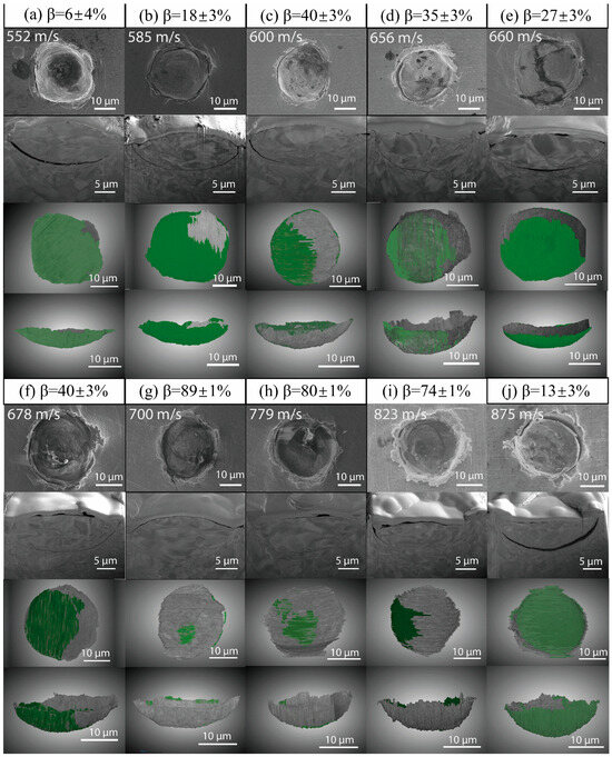
Figure 9.
Impact deformation and bonding in single-particle impacts at various velocities: 3D FIB-SEM Analysis. (a–j) SEM images show the morphological changes in single-particle impact at different impact velocities. Each small image shows the contact and deformation of particles with the substrate, and the green area represents the unbound part [81].
Furthermore, at high velocities (678 m/s to 875 m/s, Figure 9f–j), localized jetting begins to occur, promoting stronger metal-to-metal bonding, especially in shearing zones, where the strain at the interface is sufficiently high to overcome oxide layers and create direct metallic contact. As velocity continues to increase, jetting intensifies, and plastic flow at the interface becomes more pronounced, resulting in deeper hydrodynamic penetration (HDP). However, even at these high velocities, unbonded regions persist, and bonding quality begins to decrease, particularly beyond approximately 1.3 times the critical velocity, where particle deformation reaches its extreme and interface peeling occurs. Existing models typically overlook the complexities of jetting and HDP, leading to an incomplete representation of the material behavior at high velocities. Therefore, to improve simulation accuracy, models must better incorporate factors such as jetting, the critical jetting bonding region, localized deformation, and the onset of HDP, all of which are crucial to understanding particle impact dynamics at higher speeds.
Another most important factor is the inability to remove total oxide layers using classic gas–thermal technologies. Widely used mechanical surface cleaning and preparation technologies, like sand blasting, as well as spraying of compositions with ceramic additives, can be characterized by only partial destruction and fragmentation of surface oxide films. All the typical technological processes of gas–thermal spraying onto substrates uncleaned by chemical methods demonstrate nearly the same problem: the critical influence of surface oxide layer fragments on the particle–substrate and particle–particle bonding processes. Thus, Figure 10 highlights a critical deviation from the common simulation idealization of a clean or uniformly oxidized substrate. The bonding mechanism, as illustrated in the schematic (a), is not achieved on a pristine surface but is instead initiated by the fracture and removal of the native oxide layer. The experimental evidence in (b) conclusively shows that the adhesion interface is a mosaic of oxide-free zones and oxide-covered zones. Strong metallic bonding occurs only where the oxide has been effectively removed (e.g., at the peripheral zone of the crater, where material jetting occurs), while the regions where the oxide layer remains intact (e.g., in the central area of the impact crater) result in no adhesion. This demonstrates that successful bonding is a localized event governed by the non-uniform breakup of the oxide layer, a key complexity absent in oversimplified models.
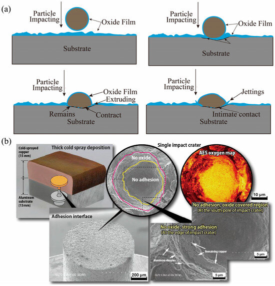
Figure 10.
Non-uniform bonding mechanism governed by oxide film fracture: (a) schematic diagram of particle impacting and bonding processes in cold spraying; (b) a pictorial view representing fractographs of cold-sprayed Cu on Al exposed after adhesion testing showing bonded zones and auger electron spectroscopic (AES) maps representing the oxide layer zone [82].
One more crucial challenge in applying theoretical models to real-world coating processes is the very specific nature of deformation processes in critical zones. This results also from unpredicted collision angles between the powder particle and the surface. Figure 11 highlights the difference between idealized predictions and actual experimental observations of cold-spray impacts. The schematic in Figure 11a,b assumes a homogeneous, single-phase substrate, showing a smooth transition in bonding behavior with increasing velocity. However, the experimental micrographs in Figure 11c–f reveal more complex behavior, with irregular deformation, asymmetric jetting, and localized bonding failures due to substrate irregularities. For instance, the Sn-Cu Figure 11c–e pairs show fragmented flow and uneven adhesion, reflecting these substrate differences. Figure 11f,g further demonstrate the specific deformation nature in gas–thermal spraying processes. Thus, at 374 m/s, Sn–Cu shows distinct particle segmentation and localized fragmentation, corresponding to solid-state mechanical interlocking. The Al–Ni interface exhibits intense material flow, jetting, and localized thermal effects, indicating that the bonding mechanism has transitioned to a thermally activated regime at 580 m/s. These observations underscore the limitations of the single-phase substrate assumption, which oversimplifies real deposition behavior, where fracture, deflection, and heterogeneous plastic flow dominate particle–substrate interactions.
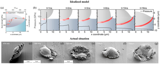
Figure 11.
Impact-induced bonding and deformation of particles at varying velocities: predictions and observations: (a,b) theoretical predictions and pressure distribution during the impact process, showing bond strength and pressure changes over time [83]; (c–e) SEM images of Sn–Cu impacts at 470, 550, and 725 m/s [78]; (f) SEM images of Sn−Cu impacts at 374 m/s; (g) SEM images of Al−Ni impacts at 580 m/s [84].
The influence of material property mismatch is further demonstrated in Figure 12a,b, where soft–hard or hard–soft configurations induce asymmetric plastic flow, stress concentration, and intermittent cracking. Such responses highlight the limitations of homogeneous substrate assumptions.
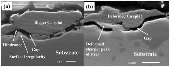
Figure 12.
Cross-sectional SEM images of cold-sprayed copper single particles deposited on SS316L steel substrates with different surface conditions: (a) as-received surface; (b) semi-polished surface [85].
Collectively, these observations underscore the need for simulations to advance beyond single-particle, ideal-surface frameworks. Future modeling efforts should incorporate multi-particle interactions, layer-by-layer accumulation, and realistic material heterogeneities, including oxides, defects, and second-phase particles. Achieving predictive fidelity will require tightly integrated approaches, combining in situ diagnostics with post-deposition microstructural analysis and rigorous benchmarking to ensure reproducibility and industrial relevance.
6. Conclusions and Recommendations
6.1. Comparative Assessment of Simulation Methods and Recommendations
Building on the applications presented in the previous sections, this section turns to a critical examination of the four major numerical approaches—Lagrangian, ALE, CEL, and SPH methods. Although these methods have provided valuable insights into particle deformation, substrate response, and coating formation mechanisms, each of them suffers from inherent drawbacks that restrict their predictive reliability. The purpose of this section is therefore to discuss the problems and current limitations of these approaches in detail, drawing on representative studies to illustrate their strengths, weaknesses, and the unresolved challenges that must be addressed in future modeling of cold spraying.
6.1.1. Assessment of the Lagrangian Method
The Lagrangian FEM approach tracks the mesh with the material and has been widely used for single-particle cold-spray impacts because of its efficiency and good agreement at moderate velocities. For example, aluminum impacts ≤ ~500 m/s can be reliably reproduced in terms of deformation shape and residual imprint when using standard constitutive laws (e.g., JC). These results show that Lagrangian FEM can capture localized plastic deformation under controlled conditions.
First, numerical stability and accuracy. At higher velocities (≥700 m/s), the extreme plastic strains cause severe element distortion and even mesh tangling, which makes the pure Lagrangian formulation unstable. Remedies such as element erosion/remeshing introduce numerical dissipation and break the continuity of stress–strain histories, degrading accuracy in high-rate regimes. Léger and Fortin [86] showed that element tangling and frequent remeshing disrupt the continuity of strain histories, degrading the accuracy of high-deformation simulations.
Second, computational cost. Maintaining element quality at high strain rates requires very fine meshes in the impact zone and very small explicit time steps, and repeated remeshing around successive splats further increases runtime. Consequently, extending Lagrangian FEM from single impacts to multi-particle deposition leads to rapidly escalating computational costs. Even when remeshing strategies are introduced to alleviate distortion, they disrupt continuity in the stress and strain fields and significantly increase the computational cost.
Third, in multi-particle simulations, progressive mesh distortion disrupts the accuracy of stress and geometry at interfaces, making predictions of bonding, jetting, and pore closure highly sensitive to mesh quality and remeshing criteria.
In summary, Lagrangian FEM is well-suited to detailed studies of single- or few-particle impacts at ~300–600 m/s, providing high-fidelity fields under moderate velocities. Its predictive capability deteriorates beyond ~700 m/s and scales poorly to multi-particle deposition because of element distortion, remeshing overhead, and loss of history consistency—motivating the use of ALE/CEL/SPH in those regimes.
6.1.2. Assessment of the ALE Method
The ALE method introduces a relative independence between the mesh and the material motion, thereby alleviating the severe mesh distortion encountered in the Lagrangian approach under high-velocity impacts. Within the particle velocity range of 300–700 m/s, ALE can provide relatively stable predictions of particle deformation and bonding behavior. Nevertheless, its application in cold-spray simulations still exhibits several critical limitations.
First, in terms of numerical stability and accuracy, when particle velocities exceed 700–800 m/s, frequent remapping of the mesh becomes necessary to maintain cell quality. This process introduces numerical dissipation, which leads to significant deviations between predicted and experimental residual stresses, with discrepancies reaching 15%–20% [23,87]. Side-by-side comparisons at ~500–610 m/s already show flattening ratio errors ranging from ~6% to nearly 46% depending on material and configuration, while experimental studies at ≥850 m/s (e.g., Ti–6Al–4V splats with FR ≈ 3.0) demonstrate deformation levels that ALE simulations typically fail to reproduce [88].
Second, the ALE method incurs a high computational cost. In multi-particle systems, each newly deposited particle may trigger extensive remeshing, causing the computational time to increase exponentially [89,90]. Even in the case of only two-particle impacts, computational demand increases drastically, which makes large-scale simulations involving hundreds of particles impractical.
Third, regarding interface and contact modeling, ALE simulations tend to produce symmetric and regular jetting and interfacial morphologies. In contrast, experimental observations show more irregular features, owing to non-ideal particle sphericity, surface oxidation layers, and substrate roughness. This discrepancy highlights the limited capability of ALE in capturing the evolution of microscopic defects such as pore closure and micro-jet formation during cold-spray deposition [87].
Beyond these general issues, recent studies provide concrete numerical evidence underscoring ALE’s shortcomings in realistic multi-particle scenarios. Badaloo et al. [91] reviewed cold-spray modeling frameworks and emphasized that the (CEL) method uniquely enables quantitative porosity evaluation via the EVF in large-scale simulations, whereas ALE and SPH lack this capability.
In summary, ALE is suitable for cold-spray studies involving moderate particle velocities (300–700 m/s) and a limited number of particles, and it shows particular advantages when dealing with complex substrate geometries. However, under conditions of high velocity (>800 m/s), large-scale deposition (>100 particles), or when investigating the evolution of microscopic defects, its predictive capability is significantly constrained. Therefore, ALE should be regarded as a complementary tool rather than a standalone method and should be combined with CEL or SPH approaches to improve predictions of porosity evolution, interfacial bonding mechanisms, and macroscopic residual stress distributions.
6.1.3. Assessment of the CEL Method
The CEL method combines an Eulerian representation of the particle domain with a Lagrangian description of the substrate, thereby avoiding the severe mesh distortion inherent to pure Lagrangian or ALE approaches. This hybrid framework enables CEL to capture jetting, fragmentation, and porosity evolution with higher fidelity, making it particularly suited for cold-spray simulations at high particle velocities.
First, in terms of numerical stability and accuracy, CEL has been validated against experimental results for both single- and multi-particle impacts. Eberle et al. [92] showed that CEL-derived descriptors (strain and temperature) can predict porosity trends in cold-sprayed titanium parts with ~92% accuracy through machine learning, confirming that CEL features align with experimental porosity across 580–900 m/s velocities and varying stand-off distances.
Second, with respect to computational cost, CEL requires fine Eulerian meshes (often with an element size < 5 µm) with a large Eulerian domain—typically several times the characteristic deposition zone thickness to avoid boundary reflections and to accommodate jetting/fragmentation, which drives up memory and runtime. Even multi-particle cases with only a few dozen particles require runtimes significantly larger than ALE, and simulating hundreds of particles typically necessitates high-performance computing clusters [31,93]. Nevertheless, Nault et al. [93] applied CEL-informed geometric porosity models to airfoil leading edges, showing that deposition defects could be predicted in complex geometries—a capability critical for titanium aerospace components.
Third, regarding interface and porosity modeling, CEL uniquely enables quantitative porosity evaluation through the EVF method, allowing void evolution to be tracked during deposition. For example, Tan [94] simulated the impact of 100 Al6061 particles (20–70 µm, 585 m/s) and reported porosity reductions from 5.08% at 600 K to 4.02% at 650 K and 3.58% at 700 K, reproducing the experimentally observed densification trend.
In summary, CEL is the most versatile and experimentally consistent framework for cold-spray modeling. In single-particle simulations, it provides accurate splat morphologies and stress fields, while in multi-particle simulations it uniquely quantifies porosity evolution and coating build-up. However, its predictive power comes at a high computational cost, and direct CEL studies on titanium particles remain limited. Thus, CEL should be considered the preferred tool for porosity evaluation and coating densification studies, but its practical application will require careful optimization of mesh resolution and access to high-performance computing resources.
6.1.4. Assessment of the SPH Method
Unlike mesh-based methods, SPH does not rely on predefined spatial connectivity, thereby avoiding mesh distortion and remeshing altogether. This feature makes SPH particularly well-suited for problems involving severe plastic deformation, high strain rates, and particle breakup and jetting—conditions that frequently occur during cold-spray deposition. In contrast to ALE and CEL, which suffer from either numerical dissipation or high computational overheads, SPH offers a natural framework to model jet formation, splashing, and crack initiation in metallic systems at impact velocities exceeding 800 m/s.
First, in terms of numerical stability and accuracy, SPH has been shown to capture particle impact, jetting, and fragmentation with strong agreement to experimental observations. Tai et al. [95] further showed that SPH simulations distinguish between spherical and elongated particle morphologies, with differences in local bonding and temperature evolution consistent with thermal spray experiments.
Second, with respect to computational cost, SPH avoids the remeshing overhead characteristic of ALE and CEL; however, its particle–particle interaction kernels necessitate very small time steps for numerical stability. Gnanasekaran [21] noted that even single-particle impacts are computationally demanding compared with finite element simulations. Large-scale deposition remains particularly intensive. More recently, Zhang et al. [44] employed a massively parallel SPH framework to simulate large-scale CSAM involving ~107 particles in the 500–1100 m/s velocity range, demonstrating stable convergence and agreement with deposition experiments.
Third, regarding interface and porosity modeling, SPH naturally represents particle breakup and jetting, pore formation, and free-surface evolution, making it well-suited for analyzing defect mechanisms. Tai et al. [96] showed that SPH simulations reproduced non-uniform jetting and localized bonding variations in Ti and Al impacts. Moreover, Jeske et al. [97] benchmarked SPH for thermal spray processes and confirmed its robustness in modeling splashing and interfacial instabilities. Nevertheless, unlike CEL, SPH lacks a built-in framework, such as EVF, for porosity quantification, and outcomes remain highly sensitive to smoothing length and particle resolution. This limits its utility for coating-scale porosity prediction, particularly in Ti systems where oxide films strongly influence adhesion. However, SPH has certain limitations. Unlike the CEL method, it lacks a built-in framework like the Effective EVF for direct porosity quantification. Additionally, the simulation results are highly sensitive to parameters like smoothing length and particle resolution. These factors limit SPH’s utility for predicting porosity at the coating scale, particularly for materials like titanium where oxide films significantly influence adhesion.
In summary, SPH excels at simulating extreme deformation, particle breakup and jetting, and high-velocity particle impacts (>800 m/s), making it a valuable complement to ALE and CEL. It eliminates mesh distortion entirely and captures irregular interfacial morphologies more realistically. However, it suffers from high computational costs and limited scalability to coating-scale simulations, and it lacks robust porosity quantification. Thus, SPH should be considered a specialized tool for investigating single- or few-particle impact physics and defect mechanisms in cold spraying—particularly for Ti and other difficult-to-spray materials—rather than for coating-scale process optimization.
6.1.5. Recommended Framework for Preliminary Simulation
To enhance the accuracy, consistency, and reproducibility of numerical simulations for existing and prospective thermal spray process, it is essential to develop standardized and systematically structured modeling frameworks. Figure 13 provides the comprehensive simulation architecture, encompassing key components across the entire simulation workflow [1,12,16,25,28,51,98,99,100,101,102,103,104,105,106,107] used by authors for a wide range of material groups, and can be recommended as the basic framework for the preliminary simulation stage of gas–thermal spraying processes.
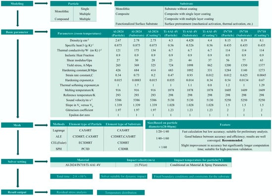
Figure 13.
Typical parameters and framework for particle cold-spray simulation based on the JC model. Notes: * The recommended coatings’ parameters have been determined for specific conventional processes; actual parameters should be optimized in alignment with real process conditions and operational requirements.
This procedure includes the classification of particle and substrate types, the incorporation of comprehensive thermophysical and mechanical property datasets—such as density, specific heat, thermal conductivity, and Johnson–Cook constitutive model parameters—under standard conditions.
The framework also delineates meshing strategies tailored to various simulation approaches, including Lagrangian, ALE, CEL, and SPH methods, with mesh resolution recommendations based on particle diameters ranging from 20 to 80 μm. Solver settings are specified for typical materials such as Al2024, Ti–6Al–4V, and IN718, covering initial particle velocities, thermal preconditions, and suitable element types for both particles and substrates. Furthermore, the framework identifies primary simulation outputs, including residual stress distribution and temperature evolution. Collectively, this framework provides a validated and generalizable foundation for conducting high-fidelity cold-spray simulations.
6.2. Comparative Assessment of Constitutive Models and Recommendations
As the results of comprehensive analyses outline, the current application of constitutive models in gas–thermal spraying (including gas–dynamic spraying processes) simulation is characterized by a trade-off between simplicity, physical fidelity, and the availability of experimental data for calibration. The typical operational domains of these models are as follows:
JC: Serves as the widely used baseline due to its simplicity and extensive parameter libraries. Typical Application Range: Strain rates up to 104–105 s−1; temperatures below ~0.6 Tm (melting point). Limitation: Accuracy degrades significantly at very high strain rates (>105 s−1) and high temperatures due to its empirical nature and inability to capture drag-dominated deformation and dynamic recovery/recrystallization.
ZA: Offers a more physics-based approach for BCC/FCC metals, with better performance in thermal-rate coupling. Typical Application Range: Strain rates up to ~106 s−1; temperatures from room temperature to near melting point. Limitation: Predictive capability declines as strain rates approach ~106 s−1, where deformation transitions to drag control. It also requires additional terms to accurately model high-strain softening mechanisms like dynamic recrystallization.
MTS: Provides a robust, physics-based framework with high predictive accuracy across a very wide range of conditions. Typical Application Range: A very broad spectrum, from quasi-static (10−4 s−1) to high strain rates (106 s−1), and temperatures from cryogenic (77 K) to near Tm. Limitation: It is notoriously data-hungry, requiring extensive and high-quality experimental data across the entire targeted strain-rate and temperature range for reliable calibration. The parameter identification process is complex and computationally expensive.
PTW: The preferred model for simulating extreme loading conditions, as it uniquely captures the transition from thermally activated to drag-dominated plasticity. Typical Application Range: Ultra-high strain rates from 103 s−1 up to 1011 s−1, applicable from room temperature to melting point. Limitation: Requires material-specific calibration in extreme conditions, where relevant experimental data (e.g., from plate impact or laser-induced shock experiments) is exceptionally scarce and difficult to obtain, severely limiting its general applicability.
Consequently, the JC model remains the default choice for general simulations where extreme conditions are not the focus. In contrast, the ZA and MTS models are selected for studies requiring enhanced physical realism at high temperatures and intermediate to high strain rates, with MTS being the more comprehensive but demanding option. The PTW model is reserved for specialized scenarios involving hypervelocity impact and other phenomena characterized by extreme strain rates.
To synthesize the insights from the preceding subsections, the following table (Table 4) contrasts the JC, ZA, MTS, and PTW models with respect to their strain-rate/temperature ranges, physical foundations, calibration data, and performance in predicting essential impact measures such as critical velocity, flattening ratio, bonding probability, and crater/residual behavior.
Table 4.
Qualitative comparison of constitutive models (JC, ZA, MTS, and PTW) [54,67,73,76,108,109,110,111,112,113,114,115,116].
6.3. Comprehensive Summary and Engineering Application Guide
This study provides the initial analytical results of the complex project aimed at developing a new gas–thermal spraying (including gas–dynamic spraying processes) simulation strategy characterized by a shift from idealized models to real processes in coating–substrate systems. It includes critical analyses of modern simulation methodologies and mathematical methods widely used for gas–dynamic spraying simulations, as well as the real deformation processes in surface layers, as the key components of the new developments.
While Table 4 provides a detailed technical comparison of the constitutive models’ theoretical foundations and performance limits, the practical selection of a model for a specific application often requires more direct guidance. Therefore, Table 5 synthesizes these technical insights into a concise selection guide, mapping recommended models to typical spraying materials and process conditions.
Table 5.
Constitutive model selection guide for typical spraying materials and applications [55,58,67,73,76,112,117,118,119,120,121,122,123,124].
The results of the comprehensive analyses of existing methods and procedures allow us to formalize the technical recommendations for precise simulation of gas–thermal spraying (including gas–dynamic spraying processes) and optimization of operating modes.
Thus, single-particle simulation can be recommended for analyses of local interaction mechanisms between particles and substrates, such as plastic deformation, stress distribution, and temperature field evolution, and prediction of critical bonding velocity and interfacial jetting. General advantages of this approach can be summarized as the efficiency of parameter analysis, such as particle velocity and size. Therefore, the Lagrangian method is suitable for medium to low velocity impacts (<500 m/s), but attention should be paid to mesh distortion issues (the recommended unit sizes are 1/50, …, 1/100 of the particle size), especially in high-speed or extreme deformation scenarios that may cause computational interruptions. Compared to the pure Lagrangian approach, the ALE method significantly reduces mesh distortion in regions of severe deformation through adaptive meshing. It is well-suited for medium- to high-velocity impact simulations (300–700 m/s), especially when particle velocities exceed the limits of the Lagrangian method. In single-particle impact simulations, the CEL method typically employs an initial velocity exceeding 500 m/s to effectively replicate dynamic material ejection phenomena under supercritical velocity conditions. In single-particle impact simulations using the SPH method, the applicable velocity range spans from moderate to extremely high speeds—ranging from several hundred to over a thousand meters per second. In theory, SPH imposes no inherent upper limit on particle velocity; however, it requires extremely small explicit time steps (on the order of 10−10 s or less) to ensure numerical stability. To balance accuracy and computational efficiency, a hybrid approach can also be adopted—modeling the particles with SPH and the substrate with a conventional finite element mesh.
Multi-particle simulation needs to consider the random distribution between particles, velocity differences, collision superposition effects, and cumulative effects of temperature deformation. The computational complexity significantly increases, especially in the resource consumption problem of high-resolution meshes or large-scale particle systems. When using the CEL method to model multi-particle deposition, a Python-generated Rosin–Rammler distribution can be employed to systematically replicate the statistical characteristics of the actual spray process—such as random spatial distribution, polydisperse particle sizes (e.g., Ti–6Al–4V powder with Dv(10) = 10 μm and Dv(50) = 29 μm), and velocity variation. This approach enables realistic capture of particle–substrate interactions and inter-particle collisions, thereby significantly enhancing the predictive accuracy of coating porosity (with an error < 5%) and residual stress fields. The ALE method treats distinct particulate materials as a continuum accumulation within the Eulerian mesh framework. Post-impact particles remain in the Eulerian domain and interact with subsequent particles, enabling explicit modeling of layer-by-layer coating deposition. This capability makes the ALE approach particularly suitable for investigating macro-scale coating properties such as porosity evolution (e.g., 2%–6.5% error versus experiments) and residual stress distribution. However, current computational constraints typically limit simulations to systems containing fewer than 100 particles while maintaining acceptable accuracy (mesh size ≤ 1 μm). The SPH method is well-suited for capturing the intense plastic flow and metallic micro-jetting that occur during thermal spray impacts. It can realistically reproduce interfacial features between particles and coatings, such as micro-jets and localized molten bands, thereby revealing a “micro-welding” mechanism in which particles bond through thin layers of molten material. The computational cost of SPH scales linearly with the number of particles. Recent studies employing message passing interface (MPI)-based parallelization have successfully extended SPH simulations to scales involving millions of particles [44]. In general, multi-particle simulation can be recommended for predicting coating performance (porosity and residual stress), optimizing process parameters (such as gas pressure and particle distribution), and dynamic deposition analysis of complex substrates (such as microstructured surfaces).
As summarized in Table 6, the Lagrangian, CEL, ALE, and SPH methods exhibit distinct characteristics in terms of their mesh structures, capabilities for handling particle deformation, and overall suitability for simulating high-strain-rate phenomena. These methods are systematically evaluated based on key performance indicators, including their effectiveness in modeling particle impact behavior, capacity to accommodate large deformations, resolution and accuracy, as well as computational cost. This comparative assessment offers valuable guidance for selecting appropriate numerical strategies in thermal spray processes.
Table 6.
Lagrangian, CEL, ALE, and SPH methods for particle deformation in gas–thermal spraying: guide for informed model selection [10,11,12,13,21,22,25,28,30,31,32,39,43,44,95,125,126,127,128,129,130,131].
Finally, complex comparative analyses of theoretical and realistic deformation and defect-generation processes in gas–thermal spraying emphasize the critical need for fundamental changes in simulation strategy. To begin with, the new approaches should integrate classic analyses of multi-particle interactions with realistic material heterogeneities and non-idealistic deformation processes. Therefore, it is crucial to integrate in situ diagnostics with post-deposition microstructural analysis and rigorous benchmarking to ensure successful industrial relevance.
On the other hand, the general focus should shift from the generation of generalized coating–substrate system characteristics to process simulation in special problematic zones. These zones, as the general sources of critical single and group defects, significantly change the real functional properties and lifespans of the coating–substrate compositions.
The pursuit of this integrated approach, combined with the development of practical methodologies, will open up numerous possibilities for implementing the new efficient engineering tool in the industrial sector.
Author Contributions
Y.W.: Conceptualization, Investigation, Data curation, Analytics, Technical recommendations development. S.M.: Supervision, Resources, Funding acquisition, General analytics, Validation, Project administration. All authors have read and agreed to the published version of the manuscript.
Funding
This research was funded by grant 010100-KZ37157701.
Institutional Review Board Statement
Not applicable.
Informed Consent Statement
Not applicable.
Data Availability Statement
Data will be made available on request.
Conflicts of Interest
The authors declare no conflicts of interest.
References
- Liu, Z.; Liu, J.; Li, H.; Wu, Z.; Zhong, Y.; Ramachandran, C.S.; Cheng, Y.; Wang, Q. Research Progress on Numerical Simulation of the Deposition and Deformation Behavior of Cold Spray Particles. Coatings 2024, 14, 913. [Google Scholar] [CrossRef]
- Yang, X.; Meng, T.; Su, Y.; Chai, X.; Guo, Z.; Ma, T.; Yin, S.; Li, W. Particle Deformation and Coating Deposition Behavior in Cold Spray Additive Manufactured Aluminum Deposit on Copper Substrate by Simulation and Experiment. J. Mater. Res. Technol. 2024, 30, 2879–2890. [Google Scholar] [CrossRef]
- Fries, T.; Belytschko, T. The Extended/Generalized Finite Element Method: An Overview of the Method and Its Applications. Numer. Meth Eng. 2010, 84, 253–304. [Google Scholar] [CrossRef]
- Bae, G.; Kumar, S.; Yoon, S.; Kang, K.; Na, H.; Kim, H.-J.; Lee, C. Bonding Features and Associated Mechanisms in Kinetic Sprayed Titanium Coatings. Acta Mater. 2009, 57, 5654–5666. [Google Scholar] [CrossRef]
- Wang, Z.; Chi, X.; Xie, Y.; Mao, P.; Yin, S. Co-Deposition Reconstruction and Defects Evolution of Cold-Sprayed Alumina/Aluminum Composites: Advanced Modeling and Experimental Validation. J. Mater. Res. Technol. 2025, 36, 4786–4802. [Google Scholar] [CrossRef]
- Meng, F.; Yue, S.; Song, J. Quantitative Prediction of Critical Velocity and Deposition Efficiency in Cold-Spray: A Finite-Element Study. Scr. Mater. 2015, 107, 83–87. [Google Scholar] [CrossRef]
- Meng, F.; Aydin, H.; Yue, S.; Song, J. The Effects of Contact Conditions on the Onset of Shear Instability in Cold-Spray. J. Therm. Spray Technol. 2015, 24, 711–719. [Google Scholar] [CrossRef]
- Yildirim, B.; Fukanuma, H.; Ando, T.; Gouldstone, A.; Müftü, S. A Numerical Investigation into Cold Spray Bonding Processes. J. Tribol. 2015, 137, 11102. [Google Scholar] [CrossRef]
- Mehta, A.; Vasudev, H.; Thakur, L. Application of Cold Spray Technology in Design and Manufacturing of Complex Geometries. Int. J. Interact. Des. Manuf. 2024, 18, 5407–5425. [Google Scholar] [CrossRef]
- Li, W.-Y.; Liao, H.; Li, C.-J.; Li, G.; Coddet, C.; Wang, X. On High Velocity Impact of Micro-Sized Metallic Particles in Cold Spraying. Appl. Surf. Sci. 2006, 253, 2852–2862. [Google Scholar] [CrossRef]
- Wang, Q.; Luo, X.; Tsutsumi, S.; Sasaki, T.; Li, C.; Ma, N. Measurement and Analysis of Cold Spray Residual Stress Using Arbitrary Lagrangian–Eulerian Method. Addit. Manuf. 2020, 35, 101296. [Google Scholar] [CrossRef]
- Wang, F.F.; Li, W.Y.; Yu, M.; Liao, H.L. Prediction of Critical Velocity during Cold Spraying Based on a Coupled Thermomechanical Eulerian Model. J. Therm. Spray Technol. 2014, 23, 60–67. [Google Scholar] [CrossRef]
- Lemiale, V.; King, P.C.; Rudman, M.; Prakash, M.; Cleary, P.W.; Jahedi, M.Z.; Gulizia, S. Temperature and Strain Rate Effects in Cold Spray Investigated by Smoothed Particle Hydrodynamics. Surf. Coat. Technol. 2014, 254, 121–130. [Google Scholar] [CrossRef]
- Li, W.Y.; Yang, K.; Yin, S.; Guo, X.P. Numerical Analysis of Cold Spray Particles Impacting Behavior by the Eulerian Method: A Review. J. Therm. Spray Technol. 2016, 25, 1441–1460. [Google Scholar] [CrossRef]
- Manap, A.; Nooririnah, O.; Misran, H.; Okabe, T.; Ogawa, K. Experimental and SPH Study of Cold Spray Impact between Similar and Dissimilar Metals. Surf. Eng. 2014, 30, 335–341. [Google Scholar] [CrossRef]
- Chakrabarty, R.; Song, J. A Modified Johnson-Cook Material Model with Strain Gradient Plasticity Consideration for Numerical Simulation of Cold Spray Process. Surf. Coat. Technol. 2020, 397, 125981. [Google Scholar] [CrossRef]
- Chakrabarty, R.; Song, J. Effect of Impact Angle on Ceramic Deposition Behavior in Composite Cold Spray: A Finite-Element Study. J. Therm. Spray Technol. 2017, 26, 1434–1444. [Google Scholar] [CrossRef]
- Mäntylä, A.; Hintikka, J.; Frondelius, T.; Vaara, J.; Lehtovaara, A.; Juoksukangas, J. Prediction of Contact Condition and Surface Damage by Simulating Variable Friction Coefficient and Wear. Tribol. Int. 2020, 143, 106054. [Google Scholar] [CrossRef]
- Li, W.-Y.; Gao, W. Some Aspects on 3D Numerical Modeling of High Velocity Impact of Particles in Cold Spraying by Explicit Finite Element Analysis. Appl. Surf. Sci. 2009, 255, 7878–7892. [Google Scholar] [CrossRef]
- Meng, F.; Fan, X.; Chi, Z.; Chen, S.; Chu, X. Modeling Parameters for Finite Element Simulation of Residual Stress in Cold Spray and the Stress Evolution and Distribution. J. Therm. Spray. Tech. 2023, 32, 1966–1984. [Google Scholar] [CrossRef]
- Gnanasekaran, B.; Liu, G.-R.; Fu, Y.; Wang, G.; Niu, W.; Lin, T. A Smoothed Particle Hydrodynamics (SPH) Procedure for Simulating Cold Spray Process—A Study Using Particles. Surf. Coat. Technol. 2019, 377, 124812. [Google Scholar] [CrossRef]
- Xie, J.; Nélias, D.; Walter-Le Berre, H.; Ogawa, K.; Ichikawa, Y. Simulation of the Cold Spray Particle Deposition Process. J. Tribol. 2015, 137, 41101. [Google Scholar] [CrossRef]
- Oyinbo, S.T.; Jen, T.-C. Feasibility of Numerical Simulation Methods on the Cold Gas Dynamic Spray (CGDS) Deposition Process for Ductile Materials. Manuf. Rev. 2020, 7, 24. [Google Scholar] [CrossRef]
- Zehtabi, N.P.; Ardeshiri Lordejani, A.; Guagliano, M.; Bagherifard, S. Numerical Simulation of Cold Spray Bonding for CrFeNi Medium-entropy Alloy. Adv. Eng. Mater. 2022, 24, 2200603. [Google Scholar] [CrossRef]
- Sun, W.; Tan, A.W.Y.; Bhowmik, A.; Marinescu, I.; Song, X.; Zhai, W.; Li, F.; Liu, E. Deposition Characteristics of Cold Sprayed Inconel 718 Particles on Inconel 718 Substrates with Different Surface Conditions. Mater. Sci. Eng. A 2018, 720, 75–84. [Google Scholar] [CrossRef]
- Ghelichi, R.; Bagherifard, S.; Guagliano, M.; Verani, M. Numerical Simulation of Cold Spray Coating. Surf. Coat. Technol. 2011, 205, 5294–5301. [Google Scholar] [CrossRef]
- Heydari Astaraee, A.; Colombo, C.; Bagherifard, S. Numerical Modeling of Bond Formation in Polymer Surface Metallization Using Cold Spray. J. Therm. Spray. Tech. 2021, 30, 1765–1776. [Google Scholar] [CrossRef]
- Zhou, H.; Jiang, S.; Li, X.; Li, C. Deposition Behavior and Bonding Mechanism during Cold Spraying of Ti6Al4V on Different Substrates. Surf. Interfaces 2022, 33, 102237. [Google Scholar] [CrossRef]
- Xie, J.; Nelias, D.; Walter-le Berre, H.; Ichikawa, Y.; Ogawa, K. Numerical Simulation of the Cold Spray Deposition Process for Aluminium and Copper. In Volume 1: Advanced Computational Mechanics; Advanced Simulation-Based Engineering Sciences; Virtual and Augmented Reality; Applied Solid Mechanics and Material Processing; Dynamical Systems and Control; American Society of Mechanical Engineers: Nantes, France, 2012; pp. 109–111. [Google Scholar]
- Yang, X.; Xu, H.; Su, Y.; Meng, T.; Chai, X.; Guo, Z.; Ma, T.; Yin, S.; Li, W. Effect of Continuous and Random Multi-Particle Impaction on the Aluminum Coating and Copper Substrate in Cold Spraying. J. Mater. Res. Technol. 2024, 33, 287–297. [Google Scholar] [CrossRef]
- Song, X.; Ng, K.L.; Chea, J.M.-K.; Sun, W.; Tan, A.W.-Y.; Zhai, W.; Li, F.; Marinescu, I.; Liu, E. Coupled Eulerian-Lagrangian (CEL) Simulation of Multiple Particle Impact during Metal Cold Spray Process for Coating Porosity Prediction. Surf. Coat. Technol. 2020, 385, 125433. [Google Scholar] [CrossRef]
- Tan, K. Numerical Study on Simulating the Deposition Process of Cold Spray Multi-Particle Al-6061 Based on CEL Method. Mech. Adv. Technol. 2024, 8, 23–29. [Google Scholar] [CrossRef]
- Terrone, M.; Ardeshiri Lordejani, A.; Kondas, J.; Bagherifard, S. A Numerical Approach to Design and Develop Freestanding Porous Structures through Cold Spray Multi-Material Deposition. Surf. Coat. Technol. 2021, 421, 127423. [Google Scholar] [CrossRef]
- Weiller, S.; Delloro, F.; Lomonaco, P.; Jeandin, M.; Garion, C. A Finite Elements Study on Porosity Creation Mechanisms in Cold Sprayed Coatings. Key Eng. Mater. 2019, 813, 358–363. [Google Scholar] [CrossRef]
- Behera, A.K.; Mantry, S.; Roy, S.; Pati, S. Improving Bond Strength and Deposition Efficiency of Ceramic Coatings via Low Pressure Cold Spraying: A Study on Hydroxyapatite Coatings with Cu-Zn Blends. Surf. Coat. Technol. 2024, 494, 131430. [Google Scholar] [CrossRef]
- Behera, A.K.; Mantry, S.; Roy, S.; Pati, S. Numerical Simulation of Cold-Sprayed Hydroxyapatite Coating on 316L Stainless Steel. Finite Elem. Anal. Des. 2023, 226, 104020. [Google Scholar] [CrossRef]
- Bolelli, G.; Dosta, S.; Lusvarghi, L.; Manfredini, T.; Guilemany, J.M.; Cano, I.G. Building up WC-Co Coatings by Cold Spray: A Finite Element Simulation. Surf. Coat. Technol. 2019, 374, 674–689. [Google Scholar] [CrossRef]
- Staubach, P. Hydro-Mechanically Coupled CEL Analyses with Effective Contact Stresses. Int. J. Numer. Anal. Methods Geomech. 2024, 48, 2207–2215. [Google Scholar] [CrossRef]
- Wang, F. Deposition Characteristic of Al Particles on Mg Alloy Micro-Channel Substrate by Cold Spray. Int. J. Adv. Manuf. Technol. 2017, 91, 791–802. [Google Scholar] [CrossRef]
- Yu, T.; Chen, M.; Wu, Z. Experimental and Numerical Study of Deposition Mechanisms for Cold Spray Additive Manufacturing Process. Chin. J. Aeronaut. 2022, 35, 276–290. [Google Scholar] [CrossRef]
- Li, W.-Y.; Zhang, C.; Li, C.-J.; Liao, H. Modeling Aspects of High Velocity Impact of Particles in Cold Spraying by Explicit Finite Element Analysis. J. Therm. Spray Technol. 2009, 18, 921–933. [Google Scholar] [CrossRef]
- Saleh, M.; Luzin, V.; Spencer, K. Analysis of the Residual Stress and Bonding Mechanism in the Cold Spray Technique Using Experimental and Numerical Methods. Surf. Coat. Technol. 2014, 252, 15–28. [Google Scholar] [CrossRef]
- Zhang, Z.L.; Gitardi, D.; Scarafile, M.; Valente, A.; Afrasiabi, M.; Bambach, M. Experimental and Numerical Investigations of Pore Formation Mechanisms in Cold Spray. J. Manuf. Process. 2024, 127, 488–510. [Google Scholar] [CrossRef]
- Zhang, Z.L.; Afrasiabi, M.; Bambach, M. A Meshless Computational Framework for Studying Cold Spray Additive Manufacturing Including Large Numbers of Powder Particles with Diverse Characteristics. Sci. Rep. 2024, 14, 11393. [Google Scholar] [CrossRef] [PubMed]
- Klippel, H.; Süssmaier, S.; Röthlin, M.; Afrasiabi, M.; Pala, U.; Wegener, K. Simulation of the Ductile Machining Mode of Silicon. Int. J. Adv. Manuf. Technol. 2021, 115, 1565–1578. [Google Scholar] [CrossRef]
- Trautmann, M.; Hertel, M.; Füssel, U. Numerical Simulation of TIG Weld Pool Dynamics Using Smoothed Particle Hydrodynamics. Int. J. Heat. Mass. Transf. 2017, 115, 842–853. [Google Scholar] [CrossRef]
- Hemeda, A.A.; Zhang, C.; Hu, X.Y.; Fukuda, D.; Cote, D.; Nault, I.M.; Nardi, A.; Champagne, V.K.; Ma, Y.; Palko, J.W. Particle-Based Simulation of Cold Spray: Influence of Oxide Layer on Impact Process. Addit. Manuf. 2021, 37, 101517. [Google Scholar] [CrossRef]
- Oyinbo, S.T.; Jen, T.-C. Investigation of the Process Parameters and Restitution Coefficient of Ductile Materials during Cold Gas Dynamic Spray (CGDS) Using Finite Element Analysis. Addit. Manuf. 2020, 31, 100986. [Google Scholar] [CrossRef]
- Yin, S.; Wang, X.; Xu, B.; Li, W. Examination on the Calculation Method for Modeling the Multi-Particle Impact Process in Cold Spraying. J. Therm. Spray Technol. 2010, 19, 1032–1041. [Google Scholar] [CrossRef]
- Gao, X.; Li, C.; Han, X.; Chen, X.; Zhao, X. Numerical Simulation and Parameter Sensitivity Analysis of Multi-Particle Deposition Behavior in HVAF Spraying. Surf. Coat. Technol. 2022, 441, 128569. [Google Scholar] [CrossRef]
- Mangalarapu, T.B.; Kumar, S.; Gandham, P.; Koppoju, S. Cold Spraying of Al-Aerospace Alloys: Ease of Coating Deposition at High Stagnation Temperatures. Surf. Coat. Technol. 2023, 467, 129703. [Google Scholar] [CrossRef]
- Assadi, H.; Gärtner, F.; Stoltenhoff, T.; Kreye, H. Bonding Mechanism in Cold Gas Spraying. Acta Mater. 2003, 51, 4379–4394. [Google Scholar] [CrossRef]
- Johnson, G.R.; Cook, W.H. Fracture Characteristics of Three Metals Subjected to Various Strains, Strain Rates, Temperatures and Pressures. Eng. Fract. Mech. 1985, 21, 31–48. [Google Scholar] [CrossRef]
- Price, M.C.; Kearsley, A.T.; Burchell, M.J. Validation of the Preston–Tonks–Wallace Strength Model at Strain Rates Approaching ∼1011 S−1 for Al-1100, Tantalum and Copper Using Hypervelocity Impact Crater Morphologies. Int. J. Impact Eng. 2013, 52, 1–10. [Google Scholar] [CrossRef]
- Nguyen, T.; Burakovsky, L.; Fensin, S.J.; Luscher, D.J.; Prime, M.B.; Cady, C.; Gray, G.T.; Jones, D.R.; Martinez, D.T.; Rowland, R.L.; et al. Calibration and Validation of the Foundation for a Multiphase Strength Model for Tin. J. Appl. Phys. 2024, 135, 225105. [Google Scholar] [CrossRef]
- Banerjee, B. An Evaluation of Plastic Flow Stress Models for the Simulation of High-Temperature and High-Strain-Rate Deformation of Metals. Acta Mater. 2010, 58, 6810–6827. [Google Scholar] [CrossRef]
- Cai, J.; Wang, K.; Han, Y. A Comparative Study on Johnson Cook, Modified Zerilli–Armstrong and Arrhenius-Type Constitutive Models to Predict High-Temperature Flow Behavior of Ti–6Al–4V Alloy in α + β Phase. High Temp. Mater. Process. 2016, 35, 297–307. [Google Scholar] [CrossRef]
- Samantaray, D.; Mandal, S.; Bhaduri, A.K. A Comparative Study on Johnson Cook, Modified Zerilli–Armstrong and Arrhenius-Type Constitutive Models to Predict Elevated Temperature Flow Behaviour in Modified 9Cr–1Mo Steel. Comput. Mater. Sci. 2009, 47, 568–576. [Google Scholar] [CrossRef]
- Li, T.; Zhao, B.; Lu, X.; Xu, H.; Zou, D. A Comparative Study on Johnson Cook, Modified Zerilli–Armstrong, and Arrhenius-Type Constitutive Models to Predict Compression Flow Behavior of SnSbCu Alloy. Materials 2019, 12, 1726. [Google Scholar] [CrossRef]
- Xu, M.; Xiao, Q.; Zu, X.; Tan, Y.; Huang, Z. Constitutive Modeling of Annealed OFHC with Wide Strain-Rate and Temperature Effects: Incorporating Dislocation Dynamics and Normalized Microstructural Size Evolution. Materials 2023, 16, 6517. [Google Scholar] [CrossRef]
- Wang, X.; Huang, C.; Zou, B.; Liu, H.; Zhu, H.; Wang, J. Dynamic Behavior and a Modified Johnson–Cook Constitutive Model of Inconel 718 at High Strain Rate and Elevated Temperature. Mater. Sci. Eng. A 2013, 580, 385–390. [Google Scholar] [CrossRef]
- Zerilli, F.J.; Armstrong, R.W. Dislocation-Mechanics-Based Constitutive Relations for Material Dynamics Calculations. J. Appl. Phys. 1987, 61, 1816–1825. [Google Scholar] [CrossRef]
- Li, F.; Zhu, C.; Li, S.; Jiang, H.; Zhang, P.; Yang, R.; Zhao, S. A Comparative Study on Modified and Optimized Zerilli-Armstrong and Arrhenius-Type Constitutive Models to Predict the Hot Deformation Behavior in 30Si2MnCrMoVE Steel. J. Mater. Res. Technol. 2022, 20, 3918–3929. [Google Scholar] [CrossRef]
- Zerilli, F.J. Dislocation Mechanics-Based Constitutive Equations. Metall. Mater. Trans. A 2004, 35, 2547–2555. [Google Scholar] [CrossRef]
- Ding, F.; Hong, T.; Dong, F.; Huang, D. Research Advancements in High-Temperature Constitutive Models of Metallic Materials. Crystals 2025, 15, 699. [Google Scholar] [CrossRef]
- Shokry, A. Modified Fields-Backofen and Zerilli-Armstrong Constitutive Models to Predict the Hot Deformation Behavior in Titanium-Based Alloys. Sci. Rep. 2024, 14, 8359. [Google Scholar] [CrossRef]
- Lewis, J.; Pasco, J.; McCarthy, T.; Chadha, K.; Harding, M.; Aranas, C. High Strain Rate and High Temperature Mechanical Response of Additively Manufactured Alloy 625. J. Manuf. Process. 2022, 81, 922–944. [Google Scholar] [CrossRef]
- Khan, A.S.; Liang, R. Behaviors of Three BCC Metal over a Wide Range of Strain Rates and Temperatures: Experiments and Modeling. Int. J. Plast. 1999, 15, 1089–1109. [Google Scholar] [CrossRef]
- Holmedal, B. On the Formulation of the Mechanical Threshold Stress Model. Acta Mater. 2007, 55, 2739–2746. [Google Scholar] [CrossRef]
- Kotkunde, N.; Deole, A.D.; Gupta, A.K.; Singh, S.K. Comparative Study of Constitutive Modeling for Ti–6Al–4V Alloy at Low Strain Rates and Elevated Temperatures. Mater. Des. 2014, 55, 999–1005. [Google Scholar] [CrossRef]
- Banerjee, B. The Mechanical Threshold Stress Model for Various Tempers of AISI 4340 Steel. Int. J. Solids Struct. 2007, 44, 834–859. [Google Scholar] [CrossRef]
- Follansbee, P.S. Application of the Mechanical Threshold Stress Model to Large Strain Processing. Mater. Sci. Appl. 2022, 13, 300–316. [Google Scholar] [CrossRef]
- Follansbee, P.S. A Comprehensive Review of Experience with the Application of the Mechanical Threshold Stress Model. Mater. Sci. Appl. 2023, 14, 299–323. [Google Scholar] [CrossRef]
- Dowding, I.; Schuh, C.A. Metals Strengthen with Increasing Temperature at Extreme Strain Rates. Nature 2024, 630, 91–95. [Google Scholar] [CrossRef]
- Tang, Q.; Hassani, M. Quantifying Dislocation Drag at High Strain Rates with Laser-Induced Microprojectile Impact. Int. J. Plast. 2024, 175, 103924. [Google Scholar] [CrossRef]
- Schreiber, J.M.; Smid, I.; Eden, T.J.; Koudela, K.; Cote, D.; Champagne, V. Cold Spray Particle Impact Simulation Using the Preston-Tonks-Wallace Plasticity Model. Finite Elem. Anal. Des. 2021, 191, 103557. [Google Scholar] [CrossRef]
- Schmid, A.; Andrews, S. Parameter Calibration for Johnson Cook and Preston-Tonks-Wallace Material Strength Models with Uncertainty Quantification. Qeios 2022, preprint. [Google Scholar] [CrossRef]
- Hassani, M.; Veysset, D.; Sun, Y.; Nelson, K.A.; Schuh, C.A. Microparticle Impact-Bonding Modes for Mismatched Metals: From Co-Deformation to Splatting and Penetration. Acta Mater. 2020, 199, 480–494. [Google Scholar] [CrossRef]
- Tiamiyu, A.A.; Sun, Y.; Nelson, K.A.; Schuh, C.A. Site-Specific Study of Jetting, Bonding, and Local Deformation during High-Velocity Metallic Microparticle Impact. Acta Mater. 2021, 202, 159–169. [Google Scholar] [CrossRef]
- Tiamiyu, A.A.; Chen, X.; Pang, E.L.; Sun, Y.; Lienhard, J.; LeBeau, J.M.; Nelson, K.A.; Schuh, C.A. Oxide Layer Delamination: An Energy Dissipation Mechanism during High-Velocity Microparticle Impacts. Appl. Surf. Sci. 2022, 574, 151673. [Google Scholar] [CrossRef]
- Panova, V.; Schuh, C.A. Towards a Quantitative Understanding of Bonding in Supersonic Single Particle Impacts: A Three-Dimensional FIB-SEM Exploration. Acta Mater. 2024, 276, 120105. [Google Scholar] [CrossRef]
- Ichikawa, Y.; Tokoro, R.; Tanno, M.; Ogawa, K. Elucidation of Cold-Spray Deposition Mechanism by Auger Electron Spectroscopic Evaluation of Bonding Interface Oxide Film. Acta Mater. 2019, 164, 39–49. [Google Scholar] [CrossRef]
- Tang, Q.; Veysset, D.; Assadi, H.; Ichikawa, Y.; Hassani, M. Strength Gradient in Impact-Induced Metallic Bonding. Nat. Commun. 2024, 15, 9630. [Google Scholar] [CrossRef] [PubMed]
- Hassani-Gangaraj, M.; Veysset, D.; Nelson, K.A.; Schuh, C.A. Melt-Driven Erosion in Microparticle Impact. Nat. Commun. 2018, 9, 5077. [Google Scholar] [CrossRef] [PubMed]
- Singh, S.; Singh, H.; Buddu, R.K. Microstructural Investigations on Bonding Mechanisms of Cold-Sprayed Copper with SS316L Steel. Surf. Eng. 2020, 36, 1067–1080. [Google Scholar] [CrossRef]
- Léger, S.; Pepin, A. An Updated Lagrangian Method with Error Estimation and Adaptive Remeshing for Very Large Deformation Elasticity Problems: The Three-Dimensional Case. Comput. Methods Appl. Mech. Eng. 2016, 309, 1–18. [Google Scholar] [CrossRef]
- Klenam, D.; Asumadu, T.; Bodunrin, M.; Vandadi, M.; Bond, T.; Van Der Merwe, J.; Rahbar, N.; Soboyejo, W. Cold Spray Coatings of Complex Concentrated Alloys: Critical Assessment of Milestones, Challenges, and Opportunities. Coatings 2023, 13, 538. [Google Scholar] [CrossRef]
- Goldbaum, D.; Shockley, J.M.; Chromik, R.R.; Rezaeian, A.; Yue, S.; Legoux, J.-G.; Irissou, E. The Effect of Deposition Conditions on Adhesion Strength of Ti and Ti6Al4V Cold Spray Splats. J. Therm. Spray Technol. 2012, 21, 288–303. [Google Scholar] [CrossRef]
- Nélias, D.; Xie, J.; Walter-Le Berre, H.; Ichikawa, Y.; Ogawa, K. Simulation of the Cold Spray Deposition Process for Aluminum and Copper Using Lagrangian, ALE and CEL Methods. In Thermomechanical Industrial Processes; Bergheau, J., Ed.; Wiley: Hoboken, NJ, USA, 2014; pp. 321–358. ISBN 978-1-84821-358-6. [Google Scholar]
- Wu, Q.; Su, J.; Zhao, W.; Li, J.; Zhang, K.; Wang, L. Determination of Critical Velocity of Cold-Sprayed NiCoCrAlY Coating via Arbitary Lagrangian-Eulerian (ALE) Method of Finite Element Simulation. Coatings 2023, 13, 1992. [Google Scholar] [CrossRef]
- Badaloo, A.; Faizan-Ur-Rab, M.; Zahiri, S.H.; Masood, S.H.; Palanisamy, S. Assessment of Current Capabilities for Cost Effective Digital Deposition of Cold Spray Additive Structures: A Review. Int. J. Adv. Manuf. Technol. 2025, 138, 3879–3906. [Google Scholar] [CrossRef]
- Eberle, M.; Pinches, S.; Osborne, M.; Qin, K.; Ang, A. Analysis of Data Generation and Preparation for Porosity Prediction in Cold Spray Using Machine Learning. J. Therm. Spray Technol. 2024, 33, 1270–1291. [Google Scholar] [CrossRef]
- Nault, I.M.; Ellingsen, M.; Nardi, A. Prediction of Geometry-Induced Porosity in Cold Spray Additive Manufacturing of Leading Edges. J. Therm. Spray Technol. 2024, 33, 839–857. [Google Scholar] [CrossRef]
- Tan, K. Simulation of the Effect of Multi-Particle Temperature on Al6061 Coating Porosity Based on Coupled Eulerian-Lagrangian (CEL) Method. Mech. Adv. Technol. 2024, 8, 280–288. [Google Scholar] [CrossRef]
- Tai, W.K.W.; Chakrabarty, R.; Pinches, S.; Huang, X.; Lang, J.; Song, J.; Ang, A.S.M. Comparing Relative Bond Characteristics between Spherical and Elongated Morphologies for Cold Spray Process Using SPH Simulation. J. Therm. Spray Technol. 2022, 31, 2489–2504. [Google Scholar] [CrossRef]
- Tai, W.K.W.; Eberle, M.; Pinches, S.; Chan, S.S.L.; Chakrabarty, R.; Osborne, M.; Peng, D.; Jones, R.; Ang, A.S.M. Simulation and Experimental Validation of Splat Profiles for Cold-Sprayed CP-Ti with Varied Powder Morphology. Appl. Mech. 2025, 6, 33. [Google Scholar] [CrossRef]
- Jeske, S.R.; Bender, J.; Bobzin, K.; Heinemann, H.; Jasutyn, K.; Simon, M.; Mokrov, O.; Sharma, R.; Reisgen, U. Application and Benchmark of SPH for Modeling the Impact in Thermal Spraying. Comput. Part. Mech. 2022, 9, 1137–1152. [Google Scholar] [CrossRef]
- Zhong, Y.; Liu, Z.; Zhang, Y.; Cha, L.; Ramachandran, C.S.; Wang, Q. Microstructural and Interfacial Characteristics of Supersonic Reclaimed 2024Al-T3 Substrate Using Cold Sprayed 2024Al Deposit. Mater. Charact. 2024, 215, 114158. [Google Scholar] [CrossRef]
- Erice Echávarri, B. Flow and Fracture Behaviour of High Performance Alloys. Ph.D. Thesis, Universidad Politécnica de Madrid, Madrid, Spain, 2012. [Google Scholar]
- Devi, G.N.; Kumar, S.; Balaji, T.S.; Mangalarapu, T.B.; Chandrasekhar, S.B.; Gopal, A.V.; Jyothirmayi, A. Influence of Inter-Splat Bonding State of Cold Sprayed IN625 and IN718 Coatings on Mechanical and Corrosion Performance. Surf. Coat. Technol. 2022, 445, 128731. [Google Scholar] [CrossRef]
- Wang, X.; Shi, J. Validation of Johnson-Cook Plasticity and Damage Model Using Impact Experiment. Int. J. Impact Eng. 2013, 60, 67–75. [Google Scholar] [CrossRef]
- Ijaz, H.; Zain-ul-abdein, M.; Saleem, W.; Asad, M.; Mabrouki, T. Modified Johnson-Cook Plasticity Model with Damage Evolution: Application to Turning Simulation of 2XXX Aluminium Alloy. J. Mech. 2017, 33, 777–788. [Google Scholar] [CrossRef]
- Sanjeev, N.K. Verification of Johnson-Cook Material Model Constants of Aa2024-T3 for Use in Finite Element Simulation of Friction Stir Welding and Its Utilization in Severe Plastic Deformation Process Modelling. Int. J. Res. Eng. Technol. 2014, 3, 98–102. [Google Scholar] [CrossRef]
- Xie, L.; Lin, J.; Zhong, X.; Dong, B.; Wang, R.; Zhu, X.; Tong, P.; Song, W.; Sun, Y. Zero Thermal Expansion, High Specific Thermal Conductivity, and Good Machinability of Cu2P2O7/2024Al Composite. Ceram. Int. 2023, 49, 35617–35622. [Google Scholar] [CrossRef]
- Christoulis, D.K.; Guetta, S.; Guipont, V.; Jeandin, M. The Influence of the Substrate on the Deposition of Cold-Sprayed Titanium: An Experimental and Numerical Study. J. Therm. Spray Technol. 2011, 20, 523–533. [Google Scholar] [CrossRef]
- Munagala, V.N.V.; Chakrabarty, R.; Song, J.; Chromik, R.R. Effect of Metal Powder Properties on the Deposition Characteristics of Cold-Sprayed Ti6Al4V-TiC Coatings: An Experimental and Finite Element Study. Surf. Interfaces 2021, 25, 101208. [Google Scholar] [CrossRef]
- Gurusamy, M.; Sriram, S. Investigations on the Choice of Johnson–Cook Constitutive Model Parameters for the Orthogonal Cutting Simulation of Inconel 718. J. Adv. Manuf. Syst. 2023, 22, 1–25. [Google Scholar] [CrossRef]
- Preston, D.L.; Tonks, D.L.; Wallace, D.C. Model of Plastic Deformation for Extreme Loading Conditions. J. Appl. Phys. 2003, 93, 211–220. [Google Scholar] [CrossRef]
- Plohr, J. The Integration Schemes of the Preston-Tonks-Wallace (PTW) Viscoplasticity Model. In Proceedings of the Conference of the American Physical Society Topical Group on Shock Compression of Condensed Matter, Portland, OR, USA, 16–21 June 2019; p. 70038. [Google Scholar]
- Bernstein, J.; Schmidt, K.; Rivera, D.; Barton, N.; Florando, J.; Kupresanin, A. A Comparison of Material Flow Strength Models Using Bayesian Cross-Validation. Comput. Mater. Sci. 2019, 169, 109098. [Google Scholar] [CrossRef]
- Trimble, D.; Shipley, H.; Lea, L.; Jardine, A.; O’Donnell, G.E. Constitutive Analysis of Biomedical Grade Co-27Cr-5Mo Alloy at High Strain Rates. Mater. Sci. Eng. A 2017, 682, 466–474. [Google Scholar] [CrossRef]
- Kim, J.-B.; Shin, H. Comparison of Plasticity Models for Tantalum and a Modification of the PTW Model for Wide Ranges of Strain, Strain Rate, and Temperature. Int. J. Impact Eng. 2009, 36, 746–753. [Google Scholar] [CrossRef]
- Adaan-Nyiak, M.A.; Tiamiyu, A.A. Recent Advances on Bonding Mechanism in Cold Spray Process: A Review of Single-Particle Impact Methods. J. Mater. Res. 2023, 38, 69–95. [Google Scholar] [CrossRef]
- Tiamiyu, A.A.; Schuh, C.A. Particle Flattening during Cold Spray: Mechanistic Regimes Revealed by Single Particle Impact Tests. Surf. Coat. Technol. 2020, 403, 126386. [Google Scholar] [CrossRef]
- Gao, C.Y.; Zhang, L.C. Constitutive Modelling of Plasticity of Fcc Metals under Extremely High Strain Rates. Int. J. Plast. 2012, 32–33, 121–133. [Google Scholar] [CrossRef]
- Shin, H.; Ju, Y.; Choi, M.K.; Ha, D.H. Flow Stress Description Characteristics of Some Constitutive Models at Wide Strain Rates and Temperatures. Technologies 2022, 10, 52. [Google Scholar] [CrossRef]
- Dubey, N.; Kumar, S.; Laik, A.; Gopalakrishnan, S.; Kapoor, K. A Comparative Study on Johnson–Cook, Arrhenius, and Modified Zerilli–Armstrong Constitutive Models for Predicting High-Temperature Flow Stress of Zircaloy-4. Prog. Nucl. Energy 2026, 191, 106103. [Google Scholar] [CrossRef]
- Rohr, I.; Nahme, H.; Thoma, K.; Anderson, C.E. Material Characterisation and Constitutive Modelling of a Tungsten-Sintered Alloy for a Wide Range of Strain Rates. Int. J. Impact Eng. 2008, 35, 811–819. [Google Scholar] [CrossRef]
- Nemat-Nasser, S.; Guo, W.-G. Thermomechanical Response of DH-36 Structural Steel over a Wide Range of Strain Rates and Temperatures. Mech. Mater. 2003, 35, 1023–1047. [Google Scholar] [CrossRef]
- Chiou, S.-T.; Cheng, W.-C.; Lee, W.-S. Strain Rate Effects on the Mechanical Properties of a Fe–Mn–Al Alloy under Dynamic Impact Deformations. Mater. Sci. Eng. A 2005, 392, 156–162. [Google Scholar] [CrossRef]
- Goto, D.M.; Garrett, R.K.; Bingert, J.F.; Chen, S.R.; Gray, G.T. The Mechanical Threshold Stress Constitutive-Strength Model Description of HY-100 Steel. Metall. Mater. Trans. A 2000, 31, 1985–1996. [Google Scholar] [CrossRef]
- Hu, Q.; Zhao, F.; Fu, H.; Li, K.; Liu, F. Dislocation Density and Mechanical Threshold Stress in OFHC Copper Subjected to SHPB Loading and Plate Impact. Mater. Sci. Eng. A 2017, 695, 230–238. [Google Scholar] [CrossRef]
- Chen, S.R.; Gray, G.T. Constitutive Behavior of Tantalum and Tantalum-Tungsten Alloys. Metall. Mater. Trans. A 1996, 27, 2994–3006. [Google Scholar] [CrossRef]
- Razavipour, M.; Jodoin, B. Material Model for Predicting Dynamic Response of Copper and Nickel at Very High Strain Rates under Cold Spray Conditions. J. Therm. Spray Technol. 2021, 30, 324–343. [Google Scholar] [CrossRef]
- Vinay, G.; Chavan, N.M.; Kumar, S.; Jyothirmayi, A.; Bodapati, B.R. Improved Microstructure and Properties of Cold Sprayed Zinc Coatings in the as Sprayed Condition. Surf. Coat. Technol. 2022, 438, 128392. [Google Scholar] [CrossRef]
- Nikbakht, R.; Seyedein, S.H.; Kheirandish, S.; Assadi, H.; Jodoin, B. Asymmetrical Bonding in Cold Spraying of Dissimilar Materials. Appl. Surf. Sci. 2018, 444, 621–632. [Google Scholar] [CrossRef]
- Aleksieieva, O.; Dereviankina, L.; Breuninger, P.; Bozoglu, M.; Tretiakov, P.; Toporov, A.; Antonyuk, S. Simulation of Particle Interaction with Surface Microdefects during Cold Gas-Dynamic Spraying. Coatings 2022, 12, 1297. [Google Scholar] [CrossRef]
- Li, W.-Y.; Liao, H.; Li, C.-J.; Bang, H.-S.; Coddet, C. Numerical Simulation of Deformation Behavior of Al Particles Impacting on Al Substrate and Effect of Surface Oxide Films on Interfacial Bonding in Cold Spraying. Appl. Surf. Sci. 2007, 253, 5084–5091. [Google Scholar] [CrossRef]
- King, P.C.; Bae, G.; Zahiri, S.H.; Jahedi, M.; Lee, C. An Experimental and Finite Element Study of Cold Spray Copper Impact onto Two Aluminum Substrates. J. Therm. Spray Technol. 2010, 19, 620–634. [Google Scholar] [CrossRef]
- Zhou, H.; Li, C.; Bennett, C.; Tanvir, H.; Li, C. Numerical Analysis of Deformation Behavior and Interface Bonding of Ti6Al4V Particle After Subsequent Impact During Cold Spraying. J. Therm. Spray Tech. 2021, 30, 1093–1106. [Google Scholar] [CrossRef]
- Han, X.; Li, C.; Wang, X.; Mei, H. Study on Interface Bonding Mechanisms for High-Velocity Oxygen-Fuel Spraying of WC-12Co Coatings on AZ31B Magnesium Alloy. J. Mater. Res. Technol. 2024, 33, 5821–5837. [Google Scholar] [CrossRef]
Disclaimer/Publisher’s Note: The statements, opinions and data contained in all publications are solely those of the individual author(s) and contributor(s) and not of MDPI and/or the editor(s). MDPI and/or the editor(s) disclaim responsibility for any injury to people or property resulting from any ideas, methods, instructions or products referred to in the content. |
© 2025 by the authors. Licensee MDPI, Basel, Switzerland. This article is an open access article distributed under the terms and conditions of the Creative Commons Attribution (CC BY) license (https://creativecommons.org/licenses/by/4.0/).