Abstract
Multilayer Cr/CrN coatings with two-, four-, and six-layer architectures were deposited on E110 zirconium alloy substrates by reactive magnetron sputtering. The effect of layer number on structure, phase composition, and performance was systematically investigated. XRD revealed that the coatings consisted mainly of CrN and Cr phases, with an increase in the CrN fraction and texture intensity as the number of layers increased. Cross-sectional SEM and EDS analyses confirmed the formation of dense multilayer structures with clear Cr/CrN interfaces and strong adhesion to the substrate. Nanoindentation showed a progressive increase in hardness and Young’s modulus from 2.59 ± 0.09 GPa and 97 ± 2 GPa (two-layer) to 5.0 ± 0.27 GPa and 110 ± 4 GPa (six-layer), respectively. Tribological and scratch tests demonstrated that the 6-layer coating exhibited the lowest wear rate and highest adhesion strength (Lc ≈ 20.5 N).
1. Introduction
Zirconium alloys (Zr alloys) are widely used as cladding material for light water reactor (LWR) fuel elements due to their combination of low thermal neutron capture cross section, high corrosion resistance in high-temperature water, and satisfactory mechanical properties. However, under emergency overheating conditions, the vulnerability of such alloys becomes apparent, as follows: during the accident at the Fukushima Daiichi Nuclear Power Plant, a problem was identified involving the rapid interaction of zirconium with steam at high temperatures, accompanied by intense hydrogen release and exothermic heat release. This circumstance raised serious concerns about the operational reliability of traditional cladding and stimulated international efforts to create so-called accident-tolerant fuel (ATF) [].
One of the key areas in the design of ATF is the development of modified cladding materials with improved characteristics as follows: increased radiation resistance, resistance to uniform and localized corrosion, low neutron capture cross section, stable thermal conductivity, and the ability to withstand high-temperature oxidation under accident conditions while maintaining the mechanical integrity of the fuel assembly [,,]. One of the most technologically feasible approaches is to apply protective coatings to the surface of Zr alloys. This method does not require significant changes to the design of fuel assemblies, which makes it promising for widespread implementation in existing reactor fleets [].
Among the various coatings being studied, considerable attention is being paid to coatings based on metallic chromium (Cr). Chromium has a high melting point, good resistance to high-temperature oxidation, and a thermal expansion coefficient close to that of Zr alloys, which ensures favorable compatibility with the substrate [,,,,]. A number of studies have shown that Cr coatings significantly increase the resistance of Zr alloys to oxidation under emergency overheating conditions. For example, Cr-coated samples withstood prolonged exposure to steam at 1200 °C, while untreated samples were destroyed [,,]. In addition, coatings increase surface hardness, reduce the likelihood of mechanical damage, and improve the thermal conductivity and wettability of shells [,,].
However, the maximum operating temperature of such systems is limited to ~1200–1250 °C, since at higher temperatures, active mutual diffusion of Cr and Zr occurs with the formation of a low-melting Cr–Zr eutectic (Tmelt~1332 °C), which leads to a loss of the protective properties of the coating []. To prevent interdiffusion at the Cr/Zr interface, the use of barrier sublayers based on refractory metals (Mo, Ta, Nb, and Re) [,,,] or ceramic compounds (CrN and ZrO2) [,,,] is proposed. Despite their effectiveness, metal sublayers have thickness limitations due to their high neutron capture cross section (e.g., for Ta and Re, 20.6 and 89.7 b, respectively), which reduces neutron economy [,]. Ceramic sublayers, on the other hand, have low diffusion mobility and high chemical resistance.
Of particular interest are multilayer coatings in which metal and ceramic layers alternate. This architecture allows for the simultaneous reduction of macro stresses, increased crack resistance, and improved barrier properties [,,,]. For example, CrN/Cr coatings with a thickness of about 2.5 μm have proven effective in oxidizing zirconium alloy E110 in air at 1100 °C for 10–40 min, and in situ XRD studies have shown the delayed formation of the Cr2Zr intermetallic phase during linear heating to 1400 °C [].
However, the influence of deposition parameters and the thickness of individual CrN/Cr layers on their microstructure, phase composition, mechanical characteristics, and resistance to high-temperature steam oxidation remains insufficiently studied. Existing publications mainly consider the influence of deposition parameters on single-layer Cr coatings [,,,,], while systematic studies of multilayer CrN/Cr structures are limited.
In view of the above, the aim of this work is to comprehensively study the influence of the thickness of the layers of a multilayer Cr/CrN coating on the formation and evolution of its microstructure, as well as on its corrosion resistance and mechanical properties. The main focus is on characterizing multilayer coatings and identifying the relationships between the layer thickness, morphology, phase composition, and mechanical characteristics of the coating. We expect that aspects related to high-temperature vapor oxidation will be considered in subsequent studies.
2. Materials and Methods
Samples of zirconium alloy E110 were used as substrates for coating application. The material was supplied by the A.A. Bochvar High-Technology Research Institute of Inorganic Materials (Moscow, Russia) in the as-received condition. The surface of the substrates was pre-treated by mechanical grinding using abrasive paper with gradually decreasing grain size (from P400 to P4000). The chemical composition of the alloy is given in Table 1.

Table 1.
Chemical composition of alloy E110, mass % according to GOST, TU: 25278.10-82.
Multilayer Cr/CrN coatings were obtained by magnetron sputtering in a reactive atmosphere using a DC magnetron sputtering system. A metal plate made of high-purity chromium (99.95%) was used as the target.
Multilayer Cr/CrN coatings were deposited by magnetron sputtering with alternating nitrogen supply on and off to form successive Cr and CrN sublayers. The Cr metal layers were deposited in a pure argon atmosphere, while the CrN layers were formed in an Ar/N2 gas mixture (80/40 sccm). These deposition cycles were repeated to obtain architectures with 2-, 4- and 6-layer structures. Each type of coating (one-, two-, four- and six-layer Cr/CrN) was deposited in a separate sputtering cycle with identical process parameters. The reproducibility of the results was ensured by repeating the experiments under the same conditions (pressure, substrate temperature, and working gas flow rate), which confirmed the stability and repeatability of the deposition process.
Multilayer Cr/CrN coatings were obtained by magnetron sputtering in a reactive atmosphere on a DC magnetron sputtering system at a power of 200 W, with a gas ratio of Ar/N2 = 80/40 sccm. The deposition time for each layer was 1 h, and the total number of layers varied from 2 to 6. Before starting the process, the substrate temperature was maintained at 300 °C, after which a preliminary vacuum with a residual pressure of no more than 6.9 Pa was created in the chamber. The distance between the target and the substrate was 100 mm.
The surface morphology and microstructure of the cross sections of the coatings were examined using scanning electron microscopy (SEM) on a CIQTEK SEM3200 (CIQTEK Co., Ltd., Hefei, China), equipped with an XFlash Detector 730M-300 (Bruker) energy-dispersive X-ray microanalysis (EDS) system, which allowed us to additionally determine the elemental composition of the studied areas. The phase composition was determined by X-ray diffraction (XRD, X’Pert PRO, Philips, The Netherlands) using Cu Kα radiation (λ = 1.5406 Å) at a voltage of 40 kV and a current of 30 mA. The measurement was performed in the 2θ angle range from 20° to 90°, with a step of 0.05° and an exposure time of 1 s. The coatings and their mechanical properties (Young’s modulus and hardness) were studied using a NanoScan-4D Compact nanohardness tester (Federal State Budgetary Institution “TISNSM”, Russia). The nanoindentation of coatings was performed using the Oliver–Paaarr method with a Berkovich indenter at a load of 100 mN (ASTM E2546-07 []). The surface roughness of the coated samples was measured by scanning probe microscopy (SPM) using a SmartSPM™-1000 atomic force microscope (AFM) manufactured by AIST-NT (Moscow, Russia). Tribological tests for friction and wear were performed on a TRB3tribometer (Anton-Paar, Buchs, Switzerland) using the standard “ball-on-disc” method, where a 6.0 mm-diameter steel ball with a 100Cr6 coating was used as the counterbody, at a load of 3 N and a linear speed of 5 cm/sec, with a wear radius of curvature of 2 mm and a friction path of 100 m. To study the adhesion characteristics of coatings using the scratch method, a CSEM Micro Scratch Tester (Neuchatel, Switzerland) was used. The scratch test was performed at a maximum load of 27 N, with a normal loading rate of 26.99 N/min, an indenter displacement rate of 9.63 mm/min, a scratch length of 10 mm, and a tip radius of curvature of 100 μm.
3. Results and Discussion
Figure 1 shows the results of the study of the phase composition of Cr/CrN multilayer coatings with different layer thicknesses (two-, four-, and six-layer coatings).
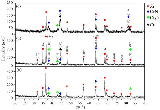
Figure 1.
Diffractograms of Cr/CrN multilayer coatings obtained by magnetron sputtering on an E110 substrate. (a) Two-layer coating, (b) four-layer coating, and (c) six-layer coating.
As shown in Figure 1, all samples contain α-Zr (substrate), cubic chromium nitride CrN (Fm-3m), dichromonitride ε-Cr2N (P-31m), and metallic chromium Cr (Im-3m) phases. Key overlaps are noted as follows: 2θ ≈ 37.5–38.0°—CrN(111)/Cr2N(110); 2θ ≈ 43.7–44.4°—CrN(200)/Cr(110); and 2θ ≈ 63.5–64.6°—CrN(220)/α-Zr(103)/Cr(200). With an increase in the number of layers (2 → 4 → 6), the CrN and Cr lines intensify, while the contribution of the α-Zr substrate decreases significantly, and the intensity of ε-Cr2N decreases to a trace level (the phase peaks are barely visible above the background and are often partially overlapped), indicating more complete nitridation and stabilization of CrN. For the 2-layer sample, the diffraction pattern is dominated by α-Zr peaks (especially (002) ~34.8° and (101) ~36.5°), while the CrN and Cr2N film peaks are distinguishable as overlaps in the ~37.8° and ~44° regions. Overlaps in the regions 2θ ≈ 37.8°, 43.7–44.4°, and 63.5–64.6° are due to the proximity of the interplanar distances of the corresponding planes (CrN(111)/Cr2N(110); CrN(200)/Cr(110); and CrN(220)/α-Zr(103)/Cr(200)) with peak widths determined by the CSR (coherent scattering regions) size, microstresses, and the instrumental function of the device. In the 4-layer sample, the contribution of the film increases as follows: CrN(111), CrN(220), and Cr(110)/Cr(200) intensify. In the six-layer sample, the film dominates as follows: the set of CrN (111/200/220/222) reflections is clearly expressed, Cr is noticeable at ~44.4° and ~64.6°, and the contribution of α-Zr is minimal.
Table 2 shows data regarding the phase composition of the coatings analyzed using the POWDERCELL (version 2.4) full-profile analysis program. The experimental and calculated diffractograms were compared graphically in terms of their scaling coefficients (relative contribution to the calculated PowderCell intensity and not interpreted as volume fractions of phases), phase lattice parameters, coherent scattering regions (CSRs) of the crystal, and microstrain value (Δd/d × 10−3).

Table 2.
Qualitative phase analysis of Cr/CrN multilayer coatings deposited on an E110 substrate with varying layer thicknesses.
During the modelling of the diffraction data in the POWDERCELL 2.4 program, the scaling coefficients obtained were used exclusively to estimate the relative contribution of phases to the calculated intensity of diffraction peaks. It should be noted that these coefficients were not interpreted as volume fractions of phases, since the analysis was qualitative rather than quantitative.
In a two-layer sample, the substrate α-Zr (~68.6%) mainly contributes to the intensity, while the film contains CrN (~6.7%) and a noticeable amount of ε-Cr2N (~22.7%), which is consistent with the early, nitrogen-deficient stages of growth. The average grain size for the film phases is ~18.2 nm (CrN), ~14.7 nm (Cr2N), and ~11.4 nm (Cr). Microstresses are moderate in CrN (≈1.31·10−3) and minimal in Cr2N (≈0.29·10−3), while in metallic Cr they are higher (≈6.15·10−3). In a four-layer sample, the contribution of the film increases (CrN ~27.9%, Cr ~8.8%, α-Zr ~55.1%, Cr2N ~8.2%), with OKR values of ~17.5 nm (CrN), ~16.1 nm (Cr2N), and ~18.0 nm (Cr). For CrN, a maximum microstress (≈17.5·10−3) is recorded, which can be associated with the increased interface density and coherent growth limitations in a multilayer architecture. In the six-layer sample, the film dominates (CrN ~52.4%, Cr ~23.9%, α-Zr ~20.8%, and Cr2N ~2.8%); the CSR for CrN decreases to ~13.8 nm (domain fragmentation with a larger number of interfaces), while for Cr it increases to ~19.1 nm. CrN microstresses decrease to ≈1.03·10−3, indicating stress relaxation and stabilization of the cubic phase with an increase in total thickness, while Cr microstresses increase (≈3.98·10−3), probably due to the accumulation of mismatch at the Cr/CrN boundaries. Overall, the combination of data in the table and figure demonstrate an increase in the relative contribution of the film and the suppression of substrate signals as the number of layers increases, the gradual disappearance of ε-Cr2N and stabilization of CrN, and the evolution of CSR and microstresses, reflecting the competition between interface constraints and the subsequent stress relaxation in the multilayer stack.
The decrease in CSR and the increase in the number of interfaces in the multilayers enhance dislocation and interlayer hardening, increasing hardness and wear resistance. However, excessive microstresses increase the tendency for brittle fracturing and accelerate diffusion processes. In a six-layer sample, the combination of a small coherent scattering region of CrN with reduced ε provides an optimal balance as follows: high hardness with improved adhesion and corrosion resistance. The reduction in the proportion of ε-Cr2N further indicates the stabilization of stoichiometric CrN and an improvement in the barrier properties of the coating.
The crystallographic parameters and phase identifications were taken from the ICDD PDF-2 database using the POWDERCELL full-profile analysis program (version 2.4). Detailed results are presented in Table 3.

Table 3.
Crystallographic parameters of phases.
For comparison, the diffractogram of an uncoated E110 (Zr–1Nb) alloy substrate is also presented. Figure 2 shows the X-ray diffractogram of an uncoated E110 (Zr–1Nb) alloy substrate.
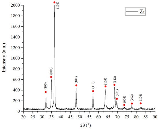
Figure 2.
X-ray diffractogram of an uncoated E110 (Zr–1Nb) alloy substrate.
All observed peaks correspond to the hexagonal close-packed phase α-Zr (PDF #05-0665, space group P63/mmc). The most intense peak at ~36.5° corresponds to reflection from the (101) plane, indicating the presence of a pronounced texture. The absence of additional peaks indicates that there are no noticeable amounts of oxide or niobium-containing phases on the substrate surface within the sensitivity range of the instrument. Markings are shown every 5° on the 2θ axis to facilitate the visualization of the peaks.
Figure 3 shows cross-sectional SEM images of multilayer Cr/CrN coatings with two, four, and six layers obtained by magnetron sputtering on an E110 substrate. All coatings form continuous contact with the substrate without cracks, pores, or signs of delamination, and the interlayer boundaries are smooth and clear.
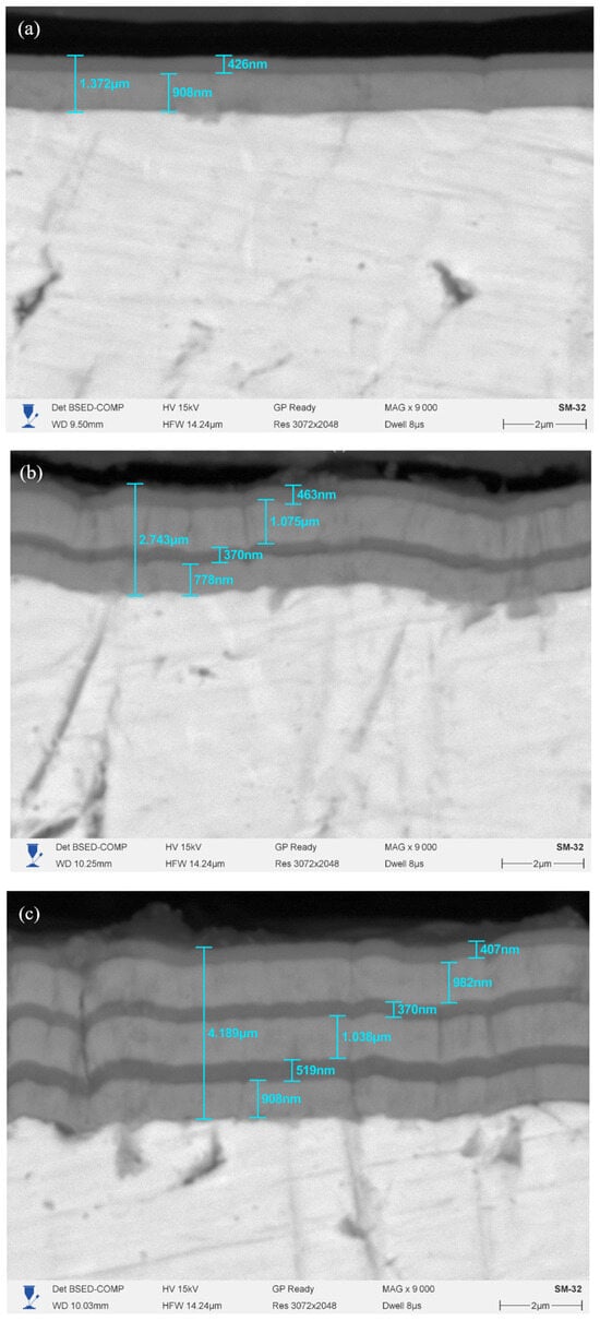
Figure 3.
Cross-sectional SEM images of multilayer Cr/CrN coatings obtained by magnetron sputtering on an E110 substrate. (a) Two-layer coating, (b) four-layer coating, and (c) six-layer coating.
The light/dark stripes correspond to alternating Cr and CrN sublayers. According to the measurements in the images, the coating thickness increases almost linearly with the number of layers.
Next, elemental mapping of the cross-section of multilayer Cr/CrN coatings obtained by magnetron sputtering with varying numbers of layers (two, four, and six layers) was performed, the results of which are shown in Figure 4.
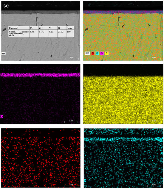
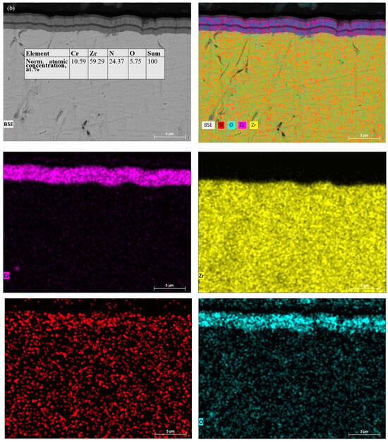
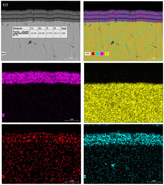
Figure 4.
SEM–EDS mapping of the cross section of multilayer Cr/CrN coatings on an E110 substrate: (a) 2-layer, (b) 4-layer, and (c) 6-layer coatings.
Morphology and EDS mapping confirm the correct formation of the multilayer Cr/CrN architecture on the E110 substrate for all three samples (two-, four-, and six-layer). That is, EDS mapping shows alternating areas corresponding to Cr and CrN sublayers, confirming the formation of the specified multilayer structure. The coatings are continuous, with a smooth substrate/film interface, and without cracks or signs of interlayer delamination. As the number of layers increases, the contribution of the coatings increases, and the areas enriched with Cr and N intensify and expand, while the contribution of Zr near the surface decreases—this is consistent with the increase in thickness and XRD data (intensification of CrN/Cr lines, weakening of α-Zr, and no oxide crystalline phases detected by XRD). EDS maps show elemental oxygen, while XRD (Figure 1) shows no crystalline oxide phases. This is consistent with the presence of a very thin (nm-level) amorphous passivation film (Cr2O3/ZrO2) and/or adsorbed surface contaminants, which XRD cannot detect due to their small thickness/proportion. A region of interest (ROI) was selected on the cross section of the coating to analyze the distribution of elements. It should be noted that the current ROIs include part of the substrate, and at an accelerating voltage of 15 kV, the EDS method may overestimate the contribution of oxygen (O) and underestimate the contribution of nitrogen (N). Nitrogen values should be considered indicative due to the low sensitivity of EDS to light elements and the possible contribution of the substrate to the analyzed area.
To assess the sharpness of the interlayer boundaries and the possible interdiffusion of elements between the coating layers, a linear element analysis (EDS line scan) was performed on cross sections of the samples in scanning electron microscope mode.
Figure 5 shows the results of the distribution of elements for coatings with different architectures as follows: (a) two-layer, (b) four-layer, and (c) six-layer Cr/CrN coatings.
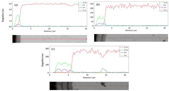
Figure 5.
Results of linear element analysis (EDS line-scan) of cross sections of Cr/CrN coatings with different multilayer architectures: (a) 2-layer, (b) 4-layer, and (c) 6-layer coating applied to an E110 alloy substrate.
For all samples studied, a sharp transition between the coating and substrate zones is observed, which is confirmed by a significant change in the intensity of Cr and Zr signals at the interface. In the coating area, a pronounced Cr and N signal characteristic of chromium nitride (CrN) is recorded, while the intensity of the Zr-Lα line decreases sharply. The absence of a smooth transition or overlap of the Cr and Zr peaks indicates the absence of noticeable mutual diffusion of elements and the preservation of clear boundaries between the layers. For multilayer coatings (Figure 5b,c), a stable distribution of Cr and N across the thickness with slight fluctuations is also observed, which indicates structural homogeneity and the high reproducibility of the deposition process.
To refine the distribution of elements throughout the coating thickness, an additional analysis was performed using optical emission glow discharge spectrometry. Figure 6 shows the profiles of the distribution of elements throughout the depth.
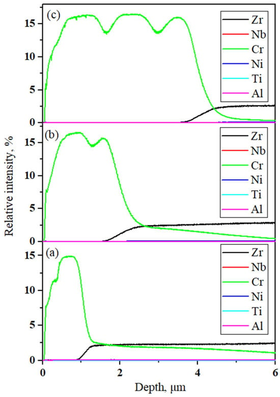
Figure 6.
Profiles of the relative intensity of elements along depth, measured by optical emission spectrometry of the glow discharge for Cr/CrN coatings of different multilayer architectures: (a) 2-layer, (b) 4-layer, and (c) 6-layer coating applied to an E110 alloy substrate.
The X-axis shows the depth (Depth, µm) corresponding to the sequential etching of the material during the analysis, which reflects the change in chemical composition from the surface to the substrate. The Y-axis shows the relative intensity, % (Relative intensity, %), characterizing the change in the intensity of the emission lines of individual elements (Cr, Zr, Nb, Ni, Ti, and Al) depending on the depth. It can be seen that the chromium (Cr) content significantly predominates in the near-surface region, which corresponds to the coating zone, while the substrate elements (Zr and Nb) begin to be detected only when a depth of more than 2–4 μm is reached, confirming that there is a clear separation between the coating and the substrate. The presence of repeated fluctuations in Cr intensity in samples (b) and (c) indicates a pronounced multilayer structure formed by alternating layers of Cr and CrN.
The mechanical characteristics of multilayer Cr/CrN coatings with different numbers of alternating layers (two, four, and six layers) were studied using the Oliver–Paarrar nanoindentation method. Figure 7 shows the microhardness and Young’s modulus values of Cr/CrN multilayer coatings against the number of alternating layers.
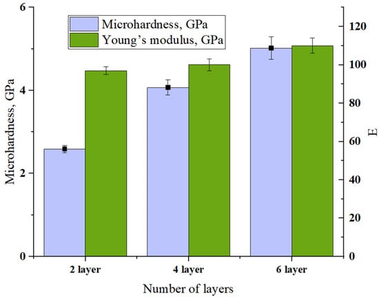
Figure 7.
Dependence of microhardness and Young’s modulus of Cr/CrN coatings on the number of layers.
It can be seen that with an increase in the number of layers from two to six, there is a regular increase in both microhardness and elastic modulus. For a two-layer coating, the values were 2.59 ± 0.09 GPa and 97 ± 2 GPa, which indicates the nature of the material is more plastic. With the transition to a four-layer architecture, the hardness increased to 4 ± 0.18 at E = 100 ± 3 GPa. The highest values (≈5 ± 0.27 GPa and ≈110 ± 4 GPa, respectively) are characteristic of the six-layer coating, which is associated with the strengthening of the structure due to an increase in the number of Cr/CrN interphase boundaries and their stabilizing effect on the deformation behavior of the system.
Topographic analysis of the surface revealed significant differences between the samples studied. Atomic force microscopy (AFM) data were used for quantitative evaluation, based on which roughness parameters were calculated. The results are summarized in Table 4.

Table 4.
Roughness parameters of Cr/CrN multilayer coatings obtained by AFM.
The surface roughness parameters show that an increase in the number of layers leads to a pronounced evolution of the coating micro-relief. For the two-layer sample, the minimum arithmetic mean roughness (Ra ≈ 12.7 nm) was recorded, but the high kurtosis (9.24) indicates the presence of individual sharp protrusions. When switching to a four-layer structure, an increase in Ra to 57.4 nm is observed, which indicates the formation of a more developed relief and is characterized by a relatively large angle φ = 26.73°, which makes its surface unfavorable for tribocontact. The six-layer coating demonstrates an optimal balance of parameters as follows: Ra = 47.8 nm with moderate values of Skew (−0.39) and Kur (1.66). The key advantage is the small angle φ = 12.33°, reflecting a “gentle” relief without sharp protrusions. This surface morphology ensures uniform load distribution and favorable conditions for stable friction.
Figure 8 shows two-dimensional topographic maps of the surface (Figure 8a–c) and three-dimensional reconstructions of the same area for multilayer Cr/CrN coatings with different numbers of layers as follows: (a) two-layer, (b) four-layer, and (c) six-layer coatings. The studies were conducted using atomic force microscopy on an area of 10 × 10 µm2.
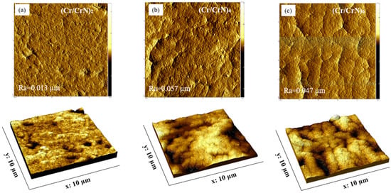
Figure 8.
Morphology of the surface of multilayer Cr/CrN coatings obtained using an atomic force microscope (AFM) after deposition. (a) Two-layer, (b) four-layer, and (c) six-layer coating.
The three-dimensional reconstructions clearly show the evolution of micro-relief with an increase in the number of layers as follows: the surface becomes more pronounced, with the appearance of large protrusions and depressions.
Although increased roughness parameters are traditionally associated with increased friction and wear coefficients, a number of studies show that this effect is not universal and largely depends on the nature of the surface micro-relief. For example, Ning et al. [] experimentally established that after laser hardening CrN coatings, increased Ra values result in the formation of a regular, gentle texture, which ensures a more uniform distribution of contact stresses and, as a result, a reduction in fretting wear. Similar patterns were observed by Singh et al. [] when analyzing the surfaces of cylinders with CrN coatings; the formation of a plateau structure helps to retain wear products and redistribute the load, which reduces the friction coefficient even at relatively high roughness. The works of Jasempoor et al. [] show that optimizing the architecture and morphology of the top layer (eliminating sharp protrusions and forming a uniform relief and stable tribofilms) provides a significant reduction in the COF and wear volume of multilayer Cr/CrN coatings.
According to classic tribology manuals, including that of Stachowiak & Batchelor (Engineering Tribology) and Bhushan (Introduction to Tribology), the effect of roughness on friction/wear is not monotonic and is determined by statistics and surface topography, rather than a single Ra value [,]. These conclusions are consistent with the third-body concept, according to which the retention of wear products/oxide films in shallow relief depressions stabilizes contact and reduces wear []. At the same time, a review of plateau surfaces shows that plateau textures provide better load-bearing capacity and less friction/wear with the right topography, even if the nominal roughness parameters are higher []. Thus, it is not the roughness value but the shape and nature of the micro-relief that determine the effectiveness of the tribological behavior of coatings. Figure 9 shows the dependence of the friction coefficient on the friction path.
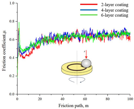
Figure 9.
Dependence of the friction coefficient on the friction path of multilayer Cr/CrN coatings with different numbers of layers.
It has been established that when varying the number of coating layers, the average friction coefficient of the coatings has the following values: µ = 0.595 for sample 1, µ = 0.620 for sample 2, and µ = 0.610 for sample 3. Despite the similarity of the values, it was the six-layer coating that demonstrated the most stable behavior with minimal fluctuations in the friction coefficient during testing, which can be attributed to the uniform surface morphology and high CrN content. Since the least wear was observed in the six-layer coating, as shown in Table 5, the wear rate was 2.26 × 10⁻⁴ mm3·N−1·m−1, which corresponds to a wear volume of 0.068 mm3. For comparison, these values were significantly higher for the two- and four-layer samples. Thus, it was the six-layer architecture that demonstrated the highest wear resistance, which can be explained by the combination of high hardness, increased CrN phase content, and optimal surface morphology.

Table 5.
Friction and wear parameters of Cr/CrN multilayer coatings.
To study the dependence of wear depth on scan length, a contact profilometer was used, which allows high-precision recording of the geometry of the worn surface. The obtained values of the depth and width of the wear profile were used to quantitatively assess the degree of coating wear.
The quantitative determination of the wear volume was carried out using Origin 2017 software (version 9.4) by calculating the area under the curve, which made it possible to determine the cross-sectional area of the wear track (S).
The wear volume (V) was calculated using Equation (1), expressed as follows:
∆V = S × l
ΔV—sample volume loss, mm3;
l—groove length, mm;
S—wear groove cross-sectional area, mm2.
The wear rate (k) was determined using Equation (2), expressed as follows:
where k is the wear rate, V is the wear volume, F is the applied load, and S is the total sliding distance.
k = V/(F × S) mm3/Nm
The obtained values of the friction coefficient (μ = 0.59–0.62) and specific wear rate (2.26 × 10⁻⁴–8.64 × 10⁻⁴ mm3·N−1·m−1) are within the ranges given in the literature for Cr/CrN coatings obtained by reactive magnetron sputtering or cathode arc deposition. Thus, according to [,], the friction coefficient for multilayer Cr/CrN coatings is typically 0.45–0.65, and the wear rate is about 10−4 mm3·N−1·m−1. Similar values are reported in [,], where a decrease in wear is noted with an increase in the number of layers. According to the results of [,] and a study of the influence of the double-layer period on the properties of Cr/CrN coatings, optimizing the thickness and number of layers allows the friction coefficient to be reduced to 0.5 and the specific wear rate to be reduced by more than 90% compared to single-layer CrN. Thus, the data presented in this work are in good agreement with the published results and confirm that increasing the number of Cr/CrN interfaces contributes to an increase in hardness and a reduction in wear due to mechanical reinforcement and suppression of crack propagation between layers.
Next, the adhesion and cohesion properties of multilayer Cr/CrN coatings formed on an E110 substrate were evaluated using progressive scratch testing. Figure 10 shows the dependence of normal force (brown curve), friction force (purple), friction coefficient (red), acoustic emission (blue), and indenter penetration depth (light blue) on groove length. The right side shows optical images of the scratch mark at different loads, illustrating the stages of coating degradation—from the appearance of the first cracks to complete detachment.
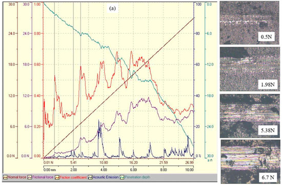
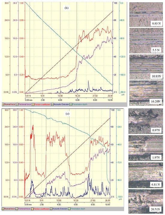
Figure 10.
Scratch test results for Cr/CrN multilayer coatings deposited by magnetron sputtering with different numbers of layers: (a) 2 layers, (b) 4 layers, and (c) 6 layers.
Critical loads (Lc1–Lc4) were determined during scratch testing using Scratch Software V4.0 (CSM Instruments/Anton Paar), which automatically records changes in the normal and tangential force, friction coefficient, indenter penetration depth, and acoustic emission signal (AE). The analysis took into account characteristic AE spikes corresponding to local coating failures, with the AE threshold being determined automatically at a sensitivity level of 5, without visually displaying that on the graph. Scratch tests for all coatings were performed three times, with the critical load values Lc1–Lc4 differing insignificantly, which confirms the reproducibility of the results. The graphs in Figure 10 show typical curves corresponding to one of the repetitions.
In the initial stages of testing, the friction coefficient for all multilayer structures remained in the range of 0.2–0.3 and remained stable. The first defects (force N1), characterized by cohesive failures in the coating volume, were recorded at loads of about 0.5 N for the two-layer sample, 0.93 N for the four-layer sample, and 0.97 N for the six-layer sample. These defects were accompanied by slight fluctuations in the friction coefficient and the first peaks of acoustic emission, indicating local damage without loss of adhesion to the substrate. With further increases in load (force N2 and N3), transverse cracks and partial delamination were observed, accompanied by a sharp increase in the friction coefficient and an increase in the intensity of acoustic signals. Complete destruction of the coatings (force N4) occurred at loads of about 7,6 N for the two-layer coating, 16 N for the four-layer coating, and 20.5 N for the six-layer coating. At this stage, the friction coefficient reached maximum values of 0.6–0.7, and acoustic emission recorded multiple peaks corresponding to large-scale coating detachment and substrate exposure.
A comparative analysis showed that multilayer systems are more resistant to progressive failure than a two-layer structure as follows: the first defects appear at higher loads, and acoustic emission remains low until critical values are reached. The most balanced strength and adhesion values were demonstrated by the four-layer coating, while the six-layer coating provided the maximum ultimate adhesion load but showed less stability at intermediate stages of degradation.
4. Conclusions
Increasing the number of Cr/CrN layers from two to six leads to significant improvements in the structural and mechanical performance of the coatings. The progressive layering promotes the stabilization of the cubic CrN (Fm-3m) phase and suppresses the formation of ε-Cr2N, resulting in a more uniform and refined nanocrystalline structure. The six-layer architecture forms a dense and stable multilayer system with well-defined interfacial boundaries that effectively hinder stress transmission and limit diffusion processes within the coating. As the number of layers increases, both hardness and Young’s modulus consistently improve, reaching approximately 5.0 ± 0.27 GPa and 110 ± 4 GPa, respectively, for the six-layer configuration due to enhanced interfacial strengthening. AFM analysis confirms that the six-layer coating exhibits a moderate surface roughness (Ra ≈ 47.8 nm) with a smooth, plateau-like morphology that supports uniform stress distribution and contributes to stable frictional behavior. Despite showing a friction coefficient similar to the other samples (µ ≈ 0.6), the six-layer coating demonstrates the lowest wear rate (2.26 × 10⁻⁴ mm3·N−1·m−1) and the highest critical adhesion load (Lc ≈ 20.5 N), confirming its superior mechanical integrity, durability, and overall wear resistance.
Author Contributions
N.M. and B.R.: formal analysis, supervision, writing—review and editing; E.N. and A.K.: investigation, methodology; N.M. and B.R.: resources, data curation. All authors have read and agreed to the published version of the manuscript.
Funding
This study was funded by the Committee of Science of the Ministry of Science and Higher Education of the Republic of Kazakhstan (grant no. AP AP19680681).
Institutional Review Board Statement
Not applicable.
Informed Consent Statement
Not applicable.
Data Availability Statement
Data are contained within the article.
Conflicts of Interest
Author Nazerke Muktanova, Bauyrzhan Rakhadilov and Erasyl Naimankumaruly were employed by the company PlasmaScience LLP. The remaining authors declare that the research was conducted in the absence of any commercial or financial relationships that could be construed as a potential conflict of interest.
References
- Guo, Z.; Dailey, R.; Feng, T.; Zhou, Y.; Sun, Z.; Corradini, M.L.; Wang, J. Uncertainty Analysis of ATF Cr-Coated-Zircaloy on BWR in-Vessel Accident Progression during a Station Blackout. Reliab. Eng. Syst. Saf. 2021, 213, 107770. [Google Scholar] [CrossRef]
- Liu, J.; Zhang, X.; Yun, D. A complete review and a prospect on the candidate materials for accident-tolerant fuel claddings. Mater. Rev. 2018, 32, 1757–1778. [Google Scholar] [CrossRef]
- Zinkle, S.J.; Terrani, K.A.; Gehin, J.C.; Ott, L.J.; Snead, L.L. Accident Tolerant Fuels for LWRs: A Perspective. J. Nucl. Mater. 2014, 448, 374–379. [Google Scholar] [CrossRef]
- Bragg-Sitton, S.M.; Todosow, M.; Montgomery, R.; Stanek, C.R.; Montgomery, R.; Carmack, W.J. Metrics for the technical performance evaluation of light water reactor accident-tolerant fuel. Nucl. Technol. 2016, 195, 111–123. [Google Scholar] [CrossRef]
- Tang, C.; Stueber, M.; Seifert, H.J.; Steinbrueck, M. Protective Coatings on Zirconium-Based Alloys as Accident-Tolerant Fuel (ATF) Claddings. Corros. Rev. 2017, 35, 141–165. [Google Scholar] [CrossRef]
- Brachet, J.-C.; Idarraga-Trujillo, I.; Flem, M.L.; Saux, M.L.; Vandenberghe, V.; Urvoy, S.; Rouesne, E.; Guilbert, T.; Toffolon-Masclet, C.; Tupin, M.; et al. Early Studies on Cr-Coated Zircaloy-4 as Enhanced Accident Tolerant Nuclear Fuel Claddings for Light Water Reactors. J. Nucl. Mater. 2019, 517, 268–285. [Google Scholar] [CrossRef]
- Maier, B.; Yeom, H.; Johnson, G.; Dabney, T.; Walters, J.; Xu, P.; Romero, J.; Shah, H.; Sridharan, K. Development of Cold Spray Chromium Coatings for Improved Accident Tolerant Zirconium-Alloy Cladding. J. Nucl. Mater. 2019, 519, 247–254. [Google Scholar] [CrossRef]
- Ševeček, M.; Gurgen, A.; Seshadri, A.; Che, Y.; Wagih, M.; Phillips, B.; Champagne, V.; Shirvan, K. Development of Cr cold-spray-coated fuel cladding with enhanced accident tolerance. Nucl. Eng. Technol. 2018, 50, 229–236. [Google Scholar] [CrossRef]
- Kim, H.-G.; Kim, I.-H.; Jung, Y.-I.; Park, D.-J.; Park, J.-Y.; Koo, Y.-H. Adhesion Property and High-Temperature Oxidation Behavior of Cr-Coated Zircaloy-4 Cladding Tube Prepared by 3D Laser Coating. J. Nucl. Mater. 2015, 465, 531–539. [Google Scholar] [CrossRef]
- Kashkarov, E.; Afornu, B.; Sidelev, D.; Krinitcyn, M.; Gouws, V.; Lider, A. Recent advances in protective coatings for accident tolerant Zr-based fuel claddings. Coatings 2021, 11, 557. [Google Scholar] [CrossRef]
- Schuster, F.; Lomello, F.; Billard, A.; Velisa, G.; Monsifrot, E.; Bischoff, J.; Ambard, A.; Brachet, J.-C.; Lesaux, M.; Leflem, M.; et al. On-Going Studies at CEA on Chromium Coated Zirconium Based Nuclear Fuel Claddings for Enhanced Accident Tolerant LWRS Fuel. In Proceedings of the TopFuel 2015—Reactor Fuel Performance Meeting 2015, Zürich, Switzerland, 13–19 September 2015. [Google Scholar]
- Park, D.J.; Kim, H.G.; Jung, Y.I.; Park, J.H.; Yang, J.H.; Koo, Y.H. Behavior of an Improved Zr Fuel Cladding with Oxidation Resistant Coating under Loss-of-Coolant Accident Conditions. J. Nucl. Mater. 2016, 482, 75–82. [Google Scholar] [CrossRef]
- Brachet, J.-C.; Rouesne, E.; Ribis, J.; Guilbert, T.; Urvoy, S.; Nony, G.; Toffolon-Masclet, C.; Le Saux, M.; Chaabane, N.; Palancher, H.; et al. High Temperature Steam Oxidation of Chromium-Coated Zirconium-Based Alloys: Kinetics and Process. Corros. Sci. 2020, 167, 108537. [Google Scholar] [CrossRef]
- Umretiya, R.V.; Vargas, S.; Galeano, D.; Mohammadi, R.; Castano, C.E.; Rojas, J.V. Effect of Surface Characteristics and Environmental Aging on Wetting of Cr-Coated Zircaloy-4 Accident Tolerant Fuel Cladding Material. J. Nucl. Mater. 2020, 535, 152163. [Google Scholar] [CrossRef]
- Bischoff, J.; Vauglin, C.; Delafoy, C.; Barberis, P.; Perche, D.; Guerin, B.; Schuster, F.; Monsifrot, E.; Brachet, J.-C. Development of Cr-Coated Zirconium Alloy Cladding for Enhanced Accident Tolerance. In Proceedings of the TopFuel 2016—Reactor Fuel Performance Meeting 2016, Boise, ID, USA, 11–15 September 2016. [Google Scholar]
- Bischoff, J.; Delafoy, C.; Vauglin, C.; Barberis, P.; Roubeyrie, C.; Perche, D.; Duthoo, D.; Schuster, F.; Brachet, J.-C.; Schweitzer, E.W.; et al. AREVA NP’s Enhanced Accident-Tolerant Fuel Developments: Focus on Cr-Coated M5 Cladding. Nucl. Eng. Technol. 2018, 50, 223–228. [Google Scholar] [CrossRef]
- Bono, M.; Pham, T.-H.; Courcelle, A.; Mallet, C.; Pegaitaz, J.; Sibille, Y.; Bossu, D.; Wu, A.; Rouesne, E.; Brachet, J.-C.; et al. Mechanical Testing of Irradiated ATF Chromium-coated Zr-based Claddings. In Proceedings of the Nuclear Materials Conference 2020, Ghent, Belgium, 26–29 October 2020. [Google Scholar] [CrossRef]
- Guo, Z.; Dailey, R.; Zhou, Y.; Sun, Z.; Wang, J.; Corradini, M.L. Effect of ATF Cr-Coated-Zircaloy on BWR In-Vessel Accident Progression during a Station Blackout. Nucl. Eng. Des. 2021, 372, 110979. [Google Scholar] [CrossRef]
- Jiang, J.; Zhai, H.; Gong, P.; Zhang, W.; He, X.; Ma, X.; Wang, B. In-Situ Study on the Tensile Behavior of Cr-Coated Zircaloy for Accident Tolerant Fuel Claddings. Surf. Coat. Technol. 2020, 394, 125747. [Google Scholar] [CrossRef]
- Yeom, H.; Maier, B.; Mariani, R.; Bai, D.; Xu, P.; Sridharan, K.; Hwasung, Y. Development of Zirconium–Silicide Coatings for Accident Tolerant Zirconium-Alloy Fuel Cladding. In Proceedings of the ICAPP 2016—International Congress on Advances in Nuclear Power Plants 2016, San Francisco, CA, USA, 17–20 April 2016; p. 2126. [Google Scholar]
- Song, L.; Huang, B.; Li, J.; Ma, X.; Liu, M.; Jiang, J.; Hu, Y. Effects of Ion Irradiation on Cr, CrN, and TiAlCrN Coated Zircaloy-4 for Accident Tolerant Fuel Claddings. Ann. Nucl. Energy 2021, 156, 108206. [Google Scholar] [CrossRef]
- Yang, J.; Steinbrück, M.; Tang, C.; Große, M.; Liu, J.; Zhang, J.; Yun, D.; Wang, S. Review on Chromium Coated Zirconium Alloy Accident Tolerant Fuel Cladding. J. Alloys Compd. 2022, 895, 162450. [Google Scholar] [CrossRef]
- Rivai, A.K.; Aziz, F.; Panitra, M.; Insani, A. Neutronic Investigation of a Light Water Reactor with SiC Ceramic as Accident Tolerant Fuel Cladding (ATFC) Material. In AIP Conference Proceedings; AIP Publishing LLC: Melville, NY, USA, 2022; Volume 2663, p. 070004. [Google Scholar] [CrossRef]
- Kim, S.-K.; Bang, J.-G.; Kim, D.-H.; Lim, I.-S.; Yang, Y.-S.; Song, K.-W.; Kim, D.-S. Hoop Strength and Ductility Evaluation of Irradiated Fuel Cladding. Nucl. Eng. Des. 2009, 239, 254–260. [Google Scholar] [CrossRef]
- Dabney, T.; Johnson, G.; Yeom, H.; Maier, B.; Walters, J.; Sridharan, K. Experimental evaluation of cold spray FeCrAl alloys coated zirconium-alloy for potential accident tolerant fuel cladding. Nucl. Mater. Energy 2019, 21, 100715. [Google Scholar] [CrossRef]
- Feng, T.; Wang, J.; Zhou, Y.; Song, P.; Wang, M.; Dailey, R.; Tian, W.; Corradini, M.L. Quantification of the Effect of Cr-Coated-Zircaloy Cladding during a Short Term Station Black Out. Nucl. Eng. Des. 2020, 363, 110678. [Google Scholar] [CrossRef]
- Kashkarov, E.B.; Sidelev, D.V.; Pushilina, N.S.; Yang, J.; Tang, C.; Steinbrueck, M. Influence of Coating Parameters on Oxidation Behavior of Cr-Coated Zirconium Alloy for Accident Tolerant Fuel Claddings. Corros. Sci. 2022, 203, 110359. [Google Scholar] [CrossRef]
- Červenka, P.; Krejčí, J.; Cvrček, L.; Rozkošný, V.; Manoch, F.; Rada, D.; Kabátová, J. Experimental study of damaged Cr-coated fuel cladding in post-accident conditions. Acta Polytech. CTU Proc. 2020, 28, 1–7. [Google Scholar] [CrossRef]
- Yokosuka, M.; Mishima, Y.; Muto, H.; Others, A. Experimental study on mechanical strength of fuel cladding tube under the loss of coolant accident. Nippon. Genshiryoku Gakkai-Shi 1963, 5, 510–519. [Google Scholar] [CrossRef]
- Pint, B.A.; Terrani, K.A.; Brady, M.P.; Cheng, T.; Keiser, J.R. High Temperature Oxidation of Fuel Cladding Candidate Materials in Steam–Hydrogen Environments. J. Nucl. Mater. 2013, 440, 420–427. [Google Scholar] [CrossRef]
- Sawarn, T.K.; Shriwastaw, R.S.; Banerjee, S.; Samanta, A.; Kumar, S.; Sunil, S.; Shah, P.K.; Singh, R.N. Influence of Temperature and Hydrogen Content on the Transverse Mechanical Properties of Zircaloy-4 Fuel Cladding. Prog. Nucl. Energy 2022, 153, 104439. [Google Scholar] [CrossRef]
- Moreira, T.A.; Lee, D.; Anderson, M.H. Critical Heat Flux on Zircaloy and Accident Tolerant Fuel Cladding under Prototypical Conditions of Pressurized and Boiling Water Reactors. Appl. Therm. Eng. 2022, 213, 118740. [Google Scholar] [CrossRef]
- He, X.; Tian, Z.; Shi, B.; Xu, X.; Meng, C.; Dang, W.; Tan, J.; Ma, X. Effect of Gas Pressure and Bias Potential on Oxidation Resistance of Cr Coatings. Ann. Nucl. Energy 2019, 132, 243–248. [Google Scholar] [CrossRef]
- Ma, X.-F.; Wu, Y.-W.; Tan, J.; Meng, C.-Y.; Yang, L.; Dang, W.-A.; He, X.-J. Evaluation of Corrosion and Oxidation Behaviors of TiAlCrN Coatings for Nuclear Fuel Cladding. Surf. Coat. Technol. 2019, 358, 521–530. [Google Scholar] [CrossRef]
- Han, X.; Chen, C.; Tan, Y.; Feng, W.; Peng, S.; Zhang, H. A Systematic Study of the Oxidation Behavior of Cr Coatings on Zry4 Substrates in High Temperature Steam Environment. Corros. Sci. 2020, 174, 108826. [Google Scholar] [CrossRef]
- Gautier, C.; Machet, J. Effects of Deposition Parameters on the Texture of Chromium Films Deposited by Vacuum Arc Evaporation. Thin Solid Film. 1996, 289, 34–38. [Google Scholar] [CrossRef]
- Chen, Q.S.; Liu, C.H.; Zhang, R.Q.; Yang, H.Y.; Wei, T.G.; Wang, Y.; Li, Z.; He, L.X.; Wang, J.; Wang, L.; et al. Microstructure and High-Temperature Steam Oxidation Properties of Thick Cr Coatings Prepared by Magnetron Sputtering for Accident Tolerant Fuel Claddings: The Role of Bias in the Deposition Process. Corros. Sci. 2020, 165, 108378. [Google Scholar] [CrossRef]
- ASTM E2546-07; Standard Practice for Instrumented Indentation Testing. ASTM International: West Conshohocken, PA, USA, 2007.
- Ning, C.; Li, K.; Tang, G.; Xie, Y.; Shang, L.; Zhang, G.; Cai, Z. Fretting Wear Performance of CrN Coating after Laser Shock Peening. Chin. J. Mech. Eng. 2025, 38, 96. [Google Scholar] [CrossRef]
- Singh, S.K.; Chattopadhyaya, S.; Pramanik, A.; Kumar, S.; Basak, A.K.; Pandey, S.M.; Litak, G. Tribological Properties of Chromium Nitride on the Cylinder Liner under the Influence of High Temperature. Materials 2020, 13, 4497. [Google Scholar] [CrossRef]
- Jasempoor, F.; Elmkhah, H.; Imantalab, O.; Fattah-Alhosseini, A. Improving the Mechanical, Tribological, and Electrochemical Behavior of AISI 304 Stainless Steel by Applying CrN Single Layer and Cr/CrN Multilayer Coatings. Wear 2022, 504–505, 204425. [Google Scholar] [CrossRef]
- Stachowiak, G.; Batchelor, A.W. Engineering Tribology, 5th ed.; Butterworth-Heinemann: Oxford, UK, 2025; ISBN 9780323858291. [Google Scholar]
- Bhushan, B.; Ko, P.L. Introduction to Tribology. Appl. Mech. Rev. 2003, 56, B6–B7. [Google Scholar] [CrossRef]
- Taylor, C.M.; Childs, P.R.N.; Berthier, Y.; Flamand, L.; Dalmaz, G.; Dowson, D.; Georges, J.M. (Eds.) The Third Body Concept: Interpretation of Tribological Phenomena; Elsevier: Amsterdam, The Netherlands, 1996; Volume 31. [Google Scholar]
- Pawlus, P.; Reizer, R.; Wieczorowski, M. Analysis of Surface Texture of Plateau-Honed Cylinder Liner—A Review. Precis. Eng. 2021, 72, 807–822. [Google Scholar] [CrossRef]
- Martinez, E.; Romero, J.; Lousa, A.; Esteve, J. Wear Behavior of Nanometric CrN/Cr Multilayers. Surf. Coat. Technol. 2003, 163–164, 571–577. [Google Scholar] [CrossRef]
- Lackner, J.M.; Waldhauser, W.; Major, L.; Kot, M. Tribology and Micromechanics of Chromium Nitride-Based Multilayer Coatings on Soft and Hard Substrates. Coatings 2014, 4, 121–138. [Google Scholar] [CrossRef]
- Polcar, T.; Martinez, R.; Vítů, T.; Kopecký, L.; Rodriguez, R.; Cavaleiro, A. High Temperature Tribology of CrN and Multilayered Cr/CrN Coatings. Surf. Coat. Technol. 2009, 203, 3254–3259. [Google Scholar] [CrossRef]
- Lu, B.; Ma, F.; Ma, D. Microstructure and Mechanical Properties of Thick Cr/CrN Multilayer Coatings by Multi-Arc Ion Plating. Rare Metal Mater. Eng. 2022, 51, 1558–1564. [Google Scholar]
- Kot, M.; Rakowski, W.A.; Major, R.; Morgiel, J. Effect of Bilayer Period on Properties of Cr/CrN Multilayer Coatings Produced by Laser Ablation. Surf. Coat. Technol. 2008, 202, 3501–3506. [Google Scholar] [CrossRef]
Disclaimer/Publisher’s Note: The statements, opinions and data contained in all publications are solely those of the individual author(s) and contributor(s) and not of MDPI and/or the editor(s). MDPI and/or the editor(s) disclaim responsibility for any injury to people or property resulting from any ideas, methods, instructions or products referred to in the content. |
© 2025 by the authors. Licensee MDPI, Basel, Switzerland. This article is an open access article distributed under the terms and conditions of the Creative Commons Attribution (CC BY) license (https://creativecommons.org/licenses/by/4.0/).