Abstract
In order to improve the wear resistance of H13 hot work die steel, high-entropy alloy composite coatings were prepared by laser cladding technology and were subsequently subjected to ultrasonic rolling. The results showed that after ultrasonic rolling, the phases of the coatings still consisted of BCC phase, TiO2, ZrO2, and B4C. The microstructure of the coatings was the equiaxed grain; however, the grain size decreased compared with that of the laser cladding coating. Under the combined effects of fine grain strengthening and work hardening, the hardness and wear resistance of the coatings treated by ultrasonic rolling were significantly improved. Among them, the coating at 0.09 MPa exhibited the best mechanical properties, with a hardness increase of 18.7% compared with the laser cladding coating and 534.9% compared with H13. At room temperature, compared with the laser cladding coating and H13, the wear rates of the coating at 0.09 MPa were reduced by 27% and 91%, respectively. At high temperatures (350 °C, 450 °C, and 550 °C), the wear rates of the coating at 0.09 MPa were reduced by 19%, 13%, and 9% compared with the laser cladding coating, and reduced by 89%, 88%, and 87% compared with H13.
1. Introduction
In the mold industry, high temperature working components such as die-casting molds, hot extrusion molds, precision forging molds, and forging press molds are required to maintain good mechanical properties under high temperature conditions [1,2,3]. H13 hot work die steel, which is currently the most widely used material, is used at the maximum temperature of 550 °C. Beyond this temperature, H13 softens rapidly, resulting in molds with a service life of only a dozen hours [4,5,6].
High-entropy alloy is a new class of alloy composed of five or more metallic elements in equal or near-equal molar ratios. By selecting the alloying elements according to specific requirements, multiple properties of the alloy are enhanced. High-entropy alloy simultaneously exhibits excellent wear resistance, corrosion resistance, and oxidation resistance, and has been widely applied in laser cladding coatings [7,8,9,10,11,12,13].
Ultrasonic rolling is a surface strengthening technique that combines ultrasonic vibration technology with conventional rolling processes, inducing severe plastic deformation in the surface layer of the material. This process refines the surface microstructure, increases dislocation density, and significantly improves the hardness [14,15] and wear resistance [16,17,18]. In the study of high-entropy alloy coatings, ultrasonic rolling helps to improve the microstructure and mechanical properties of the coating, thereby enhancing wear resistance and service stability.
Ye et al. [19] prepared a Cr–Ni alloy coating, then the coating was treated by ultrasonic rolling. The study revealed that ultrasonic rolling not only altered the phase composition but also changed the elemental distribution. After treatment, a fine grain layer with a thickness of 2.5 μm was formed on the coating. The residual stress on the surface shifted from tensile force (449.6 MPa) to compressive force (334 MPa), and the surface fracture toughness increased by 106%. Similarly, Liu et al. [20] applied ultrasonic rolling to treat a CrMnFeCoNi coating and discussed the effects of static load on the microstructural characteristics of the coating. They found that under static loads of 100 N, 200 N, and 300 N, the thicknesses of the severely plastically deformed zones were 2.51 μm, 3.03 μm, and 3.45 μm, respectively. When the static load was 300 N, the coating exhibited the highest microhardness (347 HV) and the lowest wear rate (2.6 × 10⁻⁵ mm3·N−1·m−1).
At present, there is relatively little research on laser cladding high-entropy alloys on hot work mold steel, especially the study of a high-entropy alloy + hard phase composite coating. Furthermore, there is no research about ultrasonic rolling treatment of laser cladding high-entropy alloy + hard phase composite coatings. Therefore, to improve the wear resistance of H13 hot work die steel, this study employs laser cladding to prepare a high-entropy alloy + hard phase composite coating. Then, laser cladding coating is treated by ultrasonic rolling. The effect mechanism of the ultrasonic rolling load on the microstructure and wear resistance of the laser cladding coating is systematically analyzed. The research findings offer theoretical basis and technical support for the fabrication of high-quality protective coatings on hot work die steel.
2. Experimental Materials and Methods
2.1. Experimental Materials
Annealed H13 steel was selected as the substrate material, with the dimensions of 50 mm × 30 mm × 10 mm. The chemical composition is shown in Table 1.

Table 1.
Chemical composition of H13 steel.
Cr has higher hardness and corrosion resistance and forms a dense and stable Cr2O3 oxide film under high-temperature conditions, which improves the wear resistance of the alloy. Ni improves the wettability between the substrate and coating and enhances the bonding strength. Ti is often added to alloys to improve the wear resistance of the coating and is prone to produce TiO2 oxide film under high-temperature conditions, reducing the friction coefficient of the coating. Fe improves the wettability and bonding strength of the substrate and coating. Therefore, Fe, Cr, Ni, Ti, and Zr were selected as high-entropy alloy elements.
In addition, B4C hard phase further improves the wear resistance of the coating. Based on the results of previous research, the coating with 16% B4C has the best wear resistance; therefore, FeCrNiTiZr + 16% B4C composite powder was selected as the cladding material. Element properties of the high-entropy alloys are shown in Table 2. Fe, Cr, Ni, Ti, and Zr powders were purchased from Xin Nai Metal Materials Co., Ltd. (Xingtai, Hebei Province, China), with a particle size of 300 mesh (D10 = 25 μm, D50 = 40 μm, D90 = 48 μm) and a purity of 99.0%–99.5%. B4C powder was purchased from Zhengxing Abrasives Co., Ltd. (Dunhua, Jilin Province, China), with a particle size of 0.5 μm (D10 = 0.3 μm, D50 = 0.4 μm, D90 = 0.5 μm) and a purity of 99.5%.
Table 2.
Element properties of high-entropy alloys.
In the composite powder of FeCrNiTiZr + 16%B4C, the mass fraction of FeCrNiTiZr alloy is 84%. The molar mass of each element is displayed in Table 2. For each element powder, the mass fraction Wi is calculated according to Formula (1):
In that, ni—the molar ratio of the ith element; Mi—the molar mass of the ith element; and k—the total number of elements.
In the equimolar alloy, the total molar mass of FeCrNiTiZr alloy is 305.638 g/mol, and the mass fraction of each element obtained by Formula (1) is shown in Table 3. The powders were weighed and uniformly mixed using a planetary ball mill (Honghong Instrument Equipment Factory, Huai’an, Jiangsu Province, China) at a rotation speed of 320 r/min, with a ball-to-powder mass ratio of 3:1. Before cladding, the mixed powders were preplaced on the substrate using a metal mold with dimensions of 50 mm × 30 mm × 0.7 mm.
Table 3.
Mass proportions of FeCrNiTiZr + 16% B4C composite powder.
2.2. Laser Cladding and Ultrasonic Rolling Experiments
A CO2 laser (DL-HL-T2000, Mainland Laser Equipment Co., Ltd., Shenyang, Liaoning Province, China) was used for the laser cladding experiments, and the process parameters are shown in Table 4.
Table 4.
Process parameters of laser cladding.
An ultrasonic rolling device (KZUlT-S) was used for the post-treatment of the laser cladding coating. The ultrasonic rolling process is illustrated in Figure 1 and the process parameters were listed in Table 5. The type of ultrasonic oscillation was vertical oscillation.
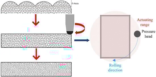
Figure 1.
Ultrasonic rolling process flow.
Table 5.
Process parameters of ultrasonic rolling.
2.3. Microstructure and Performance Characterization
2.3.1. Microstructure Characterization
The phase composition was analyzed by an X-ray diffractometer (TD-3500, Dandong Tongda Technology Co., Ltd., Dandong, Liaoning Province, China) with the following parameters: Cu target, scanning angle range of 20°–100°, scanning step of 0.034°/s, and sampling time of 0.5 s.
The samples were ground sequentially by using 120#, 240#, 600#, 1200#, 1500#, and 3000# sandpapers, followed by polishing to remove scratches. The samples were ultrasonic cleaned for 3 min and etched with aqua regia. The microstructure and elemental composition were examined using a scanning electron microscope (ZEISS Sigma 300, Carl Zeiss AG, Oberkochen, Germany) equipped with an energy-dispersive spectrometer (EDS).
2.3.2. Property Characterization
After grinding and polishing, the sample was subjected to the hardness measurement. Microhardness of the cross-section was measured by a microhardness tester (HXD-1000TMC/LCD, Shanghai Hengping Scientific Instrument Co., Ltd., Shanghai, China), the tip intender is a diamond pyramid shaped indenter. Tests were conducted from the top of the coating at intervals of 0.05 mm, with a load of 0.2 kg and a dwell time of 15 s. Three measurements were taken at each depth, and the average value was used as the final result.
The friction and wear properties were evaluated using a reciprocating friction and wear tester (MGW-02) with the following parameters: frequency of 10 Hz, load of 20 N, test duration of 20 min, stroke of 3 mm, and grinding ball radius of 3.5 mm made of TiN. The tests were conducted at room temperature, 350 °C, 450 °C, and 550 °C. The wear rate (W) is calculated according to Formula (2).
3. Experimental Results and Analysis
3.1. Effect of Static Load on Phase Composition of the Composite Coatings
Figure 2 shows XRD patterns of the composite coatings under different static loads. The phase compositions of the coatings are not altered after ultrasonic rolling, still composed of BCC phase, TiO2, ZrO2, and B4C. According to Formulas (3)–(6), the lattice constant, lattice distortion, microstrain, and dislocation density of Fe-Cr phase in the coating are calculated, as shown in Table 6.
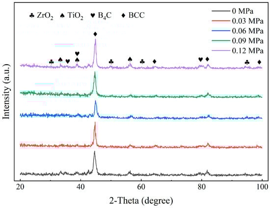
Figure 2.
XRD patterns of the composite coating under different static loads.
Table 6.
Lattice constant, lattice distortion, microstrain, and dislocation density of Fe-Cr phase in the coatings.
d is the interplanar spacing; n is the diffraction order (n = 1); λ is the incident wavelength of the X-ray (λ = 1.54056 Å); θ is the diffraction angle; and α is the actual lattice constant.
For cubic crystals, the expression of lattice distortion (ε) is as follows:
α represents the actual lattice constant, and α0 represents the theoretical lattice constant. The dislocation density of the coating is determined by the Gaussian distribution method and X-ray diffraction results. The calculation formula for dislocation density (ρ) is as follows:
β is the full width at half maximum (FWHM) of the diffraction peak; θ is the diffraction angle; D is the grain size; and ξ is the microstrain of the coating. β and θ are obtained from the XRD measurements. λ is the X-ray wavelength (λ = 1.54056 Å). By plotting the squared terms, the slope (16ξ2) and intercept (1/D2) of the fitted straight line are determined, from which ξ and ρ (≈1/D2) are ultimately calculated.
As shown in Table 6, with the increase in the static load, the lattice constant of the Fe-Cr phase decreases accordingly, indicating that the fine grain strengthening effect in the coating is further enhanced. Compared with laser cladding coatings, the dislocation density of ultrasonic rolling coatings increases. The microstrain and dislocation density of ultrasonic rolling coatings are proportional to the static load.
3.2. Effect of Static Load on the Microstructure of the Composite Coatings
The top microstructure and elemental distribution of the laser cladding coatings are shown in Figure 3. Before ultrasonic rolling, the top layer of the laser cladding coating exhibits the columnar grains and equiaxed grains, which grow along the temperature gradient direction generated during laser cladding (vertically upward).
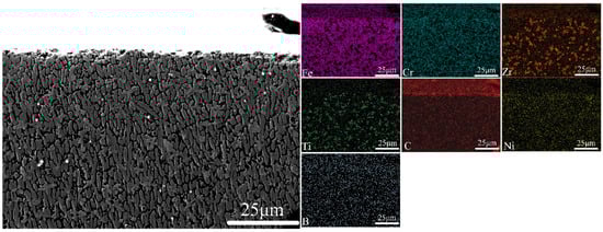
Figure 3.
Top microstructure and elemental distribution of laser cladding coating.
Top microstructure and elemental distribution of the coatings after ultrasonic rolling under different static loads are shown in Figure 4. It can be seen that the columnar grains are still observable at the top of the coating with a static load of 0.03 MPa, but the size shows a decreasing trend, which becomes more pronounced closer to the surface. In addition, the columnar grains do not grow along the temperature gradient direction, but are tilted toward the ultrasonic rolling direction.
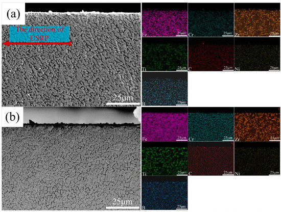
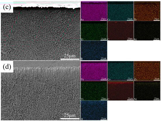
Figure 4.
Top microstructure and elemental distribution of the coatings with different static loads (a) 0.03 MPa; (b) 0.06 MPa; (c) 0.09 MPa; and (d) 0.12 MPa.
As shown in Figure 4b, when the static load reaches 0.06 MPa, the columnar grains disappear, and the microstructure is dominated by small equiaxed grains. This is mainly attributed to the high frequency impact of ultrasonic rolling, which locally raises the temperature, triggering dynamic recrystallization, breaking the original grain boundaries, and forming new equiaxed grains. When the static load reaches 0.09 MPa, the equiaxed grains are further refined (Figure 4c). Under higher static loads, severe plastic deformation occurs in the surface layer of the material, increasing dislocation density. Dislocation interactions form the entanglements, which promote the subdivision of grains into smaller sub-grains during dynamic recrystallization. A schematic illustration of grain subdivision is shown in Figure 5.
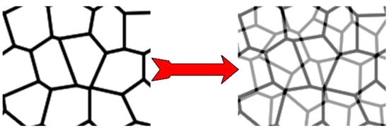
Figure 5.
Schematic diagram of grain subdivision.
As shown in Figure 4d, when the static load is 0.12 MPa, compared with the coating treated at 0.09 MPa, no significant grain refinement is observed. The limitation of grain refinement is attributed to several factors: when the deformation is excessive, the internal temperature of the material rises, triggering dynamic recovery. Grain growth offsets the refinement effect; as the grains become fine, the number of grain boundaries increases, raising the resistance to boundary migration, which further restricts refinement. Finally, the presence of hard phase particles also impedes dislocation motion, thereby hindering grain refinement.
From the distribution of Zr and Ti in Figure 4, it is evident that with the increase in static load, the hard phase particles in the top region of the coatings tend to become more refined and uniformly distributed. In particular, the coating treated by a static load of 0.09 MPa shows the most uniform distribution of Zr and Ti.
3.3. Effect of Static Load on the Microhardness of the Composite Coatings
The microhardness of the laser cladding coating and the coatings with the different static loads is shown in Figure 6. It can be seen that the microhardness of the laser cladding coating is 1069.1 HV0.2 (Figure 6a), and the coatings with static loads of 0.03 MPa, 0.06 MPa, 0.09 MPa, and 0.12 MPa are 1028.2 HV0.2, 1142.2 HV0.2, 1269.9 HV0.2, and 1237.6 HV0.2 (Figure 6b), respectively. The coating treated at 0.09 MPa exhibits the highest hardness, which is 18.7% higher than that of the laser cladding coating and 534.9% higher than that of H13 (200 HV0.2). The increase in hardness is attributed to fine grain strengthening caused by reduced grain size and work hardening due to increased dislocation density. However, when the static load reaches 0.12 MPa, the microhardness begins to decrease. This is because excessive static load results in an overly high dislocation density, promoting dynamic recovery of dislocations and weakening the dislocation strengthening effect. As shown at the top microstructure in Figure 4d, excessive static load also induces severe plastic deformation, and leads to stress concentration or microcracks, which further reduces the hardness.
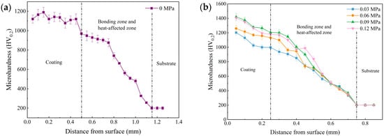
Figure 6.
Microhardness distribution of laser cladding coating and ultrasonic rolling coatings. (a) Laser cladding coating; (b) ultrasonic rolling coatings.
3.4. Effect of Static Load on the Wear Resistance of the Composite Coatings
3.4.1. Effect of Static Load on the Wear Rate of the Composite Coatings
Figure 7 shows the wear rates of H13, the laser cladding coating, and the ultrasonic rolling coatings at room temperature. Compared with the laser cladding coating, the wear rates of the ultrasonic rolling coatings decrease. Among them, the coating treated with 0.09 MPa exhibits the lowest wear rate, reduced by approximately 91% compared with H13 steel and about 27% compared with laser cladding coating.
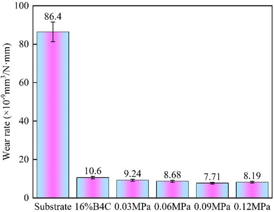
Figure 7.
Wear rates of the substrate, laser cladding coating (0.00 MPa), and ultrasonic rolling coatings at room temperature.
Wear rates of the substrate, laser cladding coating, and ultrasonic rolling coating with 0.09 MPa at 350 °C, 450 °C, and 550 °C are shown in Figure 8. At 350 °C, 450 °C, and 550 °C, the wear rates of ultrasonic rolling coating decreased by 89%, 88%, and 87% compared with those of H13, and decreased by approximately 19%, 13%, and 9% compared with those of laser cladding coating.

Figure 8.
Wear rates of the substrate, laser cladding coating (0.00 MPa), and ultrasonic rolling coating with 0.09 MPa at 350 °C, 450 °C, and 550 °C.
The improvement of wear resistance of the coatings treated by ultrasonic rolling is mainly attributed to the following factors: ultrasonic rolling induces plastic deformation, which leads to dislocation multiplication. At high dislocation densities, dislocation reacts and reorganizes to form dislocation entanglements, which further evolves into sub-grain boundaries. These sub-grain boundaries act as additional grain boundaries, further subdividing the grains and making cooperative grain–boundary sliding more difficult, thereby reducing wear rate. Additionally, the dislocations are pinned by hard phase particles in the coating, forming the Orowan strengthening mechanism [21], which increases the stress required for dislocation motion, producing a strengthening effect. Furthermore, ultrasonic rolling further refines the grains, which also contributes to higher strength in the coatings.
3.4.2. Effect of Static Load on Wear Morphologies of the Composite Coatings
To investigate the wear mechanism, the wear morphologies of the composite coatings with different static loads were analyzed. The wear morphologies at room temperature are shown in Figure 9. After ultrasonic rolling, small spalling pits appear on the coating surface. These spalling pits are caused by the detachment of hard phase particles after undergoing wear. The deformation ability of the hard phase particles differs from that of the coating matrix, resulting in uneven plastic deformation during ultrasonic rolling. Which produces stress concentration at the interfaces, promoting the initiation of cracks. The reciprocating wear accelerated crack propagation, ultimately leading to the separation of hard phase particles.
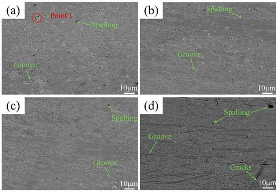
Figure 9.
Wear morphologies of ultrasonically rolled composite coatings at room temperature under different static loads: (a) 0.03 MPa; (b) 0.06 MPa; (c) 0.09 MPa; and (d) 0.12 MPa.
Under static loads of 0.03 MPa to 0.09 MPa, there are few small hard phase spalled particles, and the wear grooves are shallow, which indicates that the coatings experience pitting wear and mild abrasive wear. However, the coating treated by 0.12 MPa exhibits large spalling pits, deeper and more wear grooves, and stress cracks, as shown in Figure 9d.
Table 7 presents the element composition of point 1 in Figure 9a. It can be seen that at a static load of 0.03 MPa, there are large hard phase particles (ZrO2) in the wear surface. As the static load increases, the particle size and volume fraction of the hard phase particles decrease continuously due to the increase in wear resistance.
Table 7.
Element composition of point 1 (wt.%).
Table 8 shows the element composition of wear surface of the ultrasonic rolling coatings at room temperature. It can be observed that at 0.12 MPa, Zr and O content in the wear surface slightly decreases, which presents the decrease in the ZrO2 hard phase. This phenomenon is attributed to the excessive plastic flow of the coating under high static load, which weakens the bonding strength between the hard phase and coating substrate. In the subsequent wear process, the hard phase falls off and becomes abrasive debris, further scratching the coating surface. Ultimately, it leads to the decrease in hard phases and severe abrasive wear.
Table 8.
Element composition of the wear surface of the ultrasonic rolling coatings at room temperature (wt.%).
The wear morphologies of the ultrasonic rolling coating at 0.09 MPa at 350 °C, 450 °C, and 550 °C are shown in Figure 10. Ultrasonic rolling causes the deformation of the coating, forming micro-protrusions with the existing hard phase particles. Different from the wear process at room temperature, these micro-protrusions exhibit stronger adhesion at high temperatures, making them difficult to quickly peel off from the contact zone. On the contrary, these micro-protrusions are flattened and adhered to the wear surface. At 350 °C, the wear surface has shallow grooves and little debris. As the temperature increases, the micro-protrusions undergo high-temperature softening, which leads to partial premature detachment as wear debris. At 550 °C, more wear debris makes the grooves become deep.
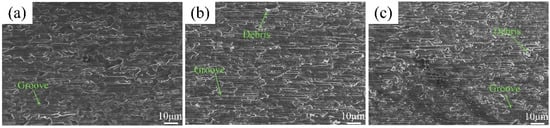
Figure 10.
Wear morphologies of the ultrasonic rolling coatings with 0.09 MPa at high temperatures: (a) 350 °C; (b) 450 °C; and (c) 550 °C.
4. Conclusions
After ultrasonic rolling treatment, the hardness and wear resistance of laser cladding high-entropy alloy composite coatings were significantly improved. The main conclusions are as follows:
- The phase composition of the composite coatings still composed of BCC phase, TiO2, ZrO2, and B4C. The plastic deformation induced by ultrasonic rolling increased the dislocation density of the coatings.
- After ultrasonic rolling, columnar grains and equiaxed grains of laser cladding composite coatings turn into equiaxed crystals. With the increase in the static load, the size of the grains decreased, and the hard phase particles became more refined and uniformly distributed.
- Under the combined effects of work hardening and fine grain strengthening, the coating treated at 0.09 MPa exhibited a hardness 18.7% higher than that of the laser cladding coating and 534.9% higher than that of H13.
- At room temperature, the wear rate of the 0.09 MPa coating decreased by 91% compared with H13 and by 27% compared with the laser cladding coating. At 350 °C, 450 °C, and 550 °C, the wear rates of the 0.09 MPa coating were reduced by approximately 89%, 88%, and 87% compared with H13, and by approximately 19%, 13%, and 9% compared with the laser cladding coating, respectively.
Author Contributions
Conceptualization, M.J., D.J., Z.Q., Y.G. and S.Z.; methodology, M.J., D.J., Z.Q., Y.G. and S.Z.; validation, M.J. and Z.Q.; formal analysis, M.J., Z.Q., L.C., F.Z. and Y.G.; investigation, M.J., D.J. and Z.S.; resources, M.J., D.J. and L.C.; data curation, M.J. and F.Z.; writing—original draft, M.J., Z.Q., Y.G. and S.Z.; writing—review and editing, M.J., Y.Z., S.Z. and Y.G.; project administration, M.J. and D.J. All authors have read and agreed to the published version of the manuscript.
Funding
This research was funded by the Jilin Provincial Department of Education of China, JJKH20240306KJ.
Data Availability Statement
Data are contained within the article.
Conflicts of Interest
The authors declare no conflict of interest.
References
- Telasang, G.; Majumdar, J.D.; Wasekar, N.; Padamanabham, G.; Manna, I. Microstructure and Mechanical Properties of Laser Clad and Post-cladding Tempered AISI H13 Tool Steel. Metall. Mater. Trans. A 2015, 46, 2309–2321. [Google Scholar] [CrossRef]
- Wang, Z.; Fu, B.; Chen, T.; Chen, L.; Yu, T.; Zhao, J. The microstructure and mechanical properties analysis of H13/Ni60 functionally gradient coating fabricated by laser cladding method. Opt. Laser Technol. 2025, 190, 113024. [Google Scholar] [CrossRef]
- Xu, L.; Sun, S.; Xia, J.; Liu, Z.; Deng, W.; Li, J.; Wu, T.; Zhu, X.; Lv, Z.; Gao, J.; et al. Effect of WC content on microstructure, mechanical properties, and tribo-corrosion behavior of laser-cladded Ni40A/WC composite coatings on H13 steel. Mater. Charact. 2025, 224, 115072. [Google Scholar] [CrossRef]
- Yang, C.; Jing, C.; Fu, T.; Lin, T.; Guo, W.; Liu, N. Effect of TiC addition on the microstructure and properties of laser cladding Ni60A coatings on H13 steel surface. Mater. Today Commun. 2024, 38, 107904. [Google Scholar] [CrossRef]
- Karmakar, D.P.; Muvvala, G.; Nath, A.K. High-temperature abrasive wear characteristics of H13 steel modified by laser remelting and cladded with Stellite 6 and Stellite 6/30% WC. Surf. Coat. Technol. 2021, 422, 127498. [Google Scholar] [CrossRef]
- Lu, J.Z.; Xue, K.N.; Lu, H.F.; Xing, F.; Luo, K.Y. Laser shock wave-induced wear property improvement and formation mechanism of laser cladding Ni25 coating on H13 tool steel. J. Mater. Process. Technol. 2021, 296, 117202. [Google Scholar] [CrossRef]
- Zhang, M.; Wang, D.; He, L.; Ye, X.; Ouyang, W.; Xu, Z.; Zhang, W.; Zhou, X. Microstructure and elevated temperature wear behavior of laser-cladded AlCrFeMnNi high-entropy alloy coating. Opt. Laser Technol. 2022, 149, 107845. [Google Scholar]
- Liu, H.; Li, X.; Liu, J.; Gao, W.; Du, X.; Hao, J. Microstructural evolution and properties of dual-layer CoCrFeMnTi0.2 high-entropy alloy coating fabricated by laser cladding. Opt. Laser Technol. 2021, 134, 106646. [Google Scholar] [CrossRef]
- Zhang, S.; Han, B.; Li, M.; Hu, C.; Zhang, Q.; Liu, X.; Wang, Y. Investigation on microstructure and properties of laser cladded AlCoCrCuFeNi high entropy alloy coating by ultrasonic impact treatment. Intermetallics 2021, 128, 107017. [Google Scholar] [CrossRef]
- Meng, G.; Yue, T.; Lin, X.; Yang, H.; Xie, H.; Ding, X. Laser surface forming of AlCoCrCuFeNi particle reinforced AZ91D matrix composites. Opt. Laser Technol. 2015, 70, 119–127. [Google Scholar] [CrossRef]
- Yao, H.; Li, Z.; Zhang, Y.; Wei, S.; Xu, G.; Yan, S.; Ren, J. Study on laser cladding system of the high-entropy alloy layer on the AZ91D magnesium. J. Laser Appl. 2022, 34, 032007. [Google Scholar] [CrossRef]
- Yue, T.M.; Xie, H.; Lin, X.; Yang, H.O.; Meng, G.H. Solidification behavior in laser cladding of AlCoCrCuFeNi high entropy alloy on magnesium substrates. J. Alloys Compd. 2014, 587, 588–593. [Google Scholar] [CrossRef]
- Gao, Y.; Ge, F.; Cui, Y.; Zhang, X.; Han, J.; Cai, Y. Study on the Strengthening Mechanism of AlCoCrFeNi2.1 Eutectic High Entropy Alloy. J. Alloys Compd. 2023, 968, 171878. [Google Scholar] [CrossRef]
- Luo, X.; Duan, H.; Li, J.; Zhan, S.; Jia, D.; Tu, J.; Li, Y. Effect of ultrasonic surface rolling on dry sliding tribological behavior of ductile iron under different normal loads. Met. Mater. Int. 2022, 28, 988–997. [Google Scholar] [CrossRef]
- Wang, T.; Wang, D.P.; Liu, G.; Gong, B.; Song, N. Investigations on the nanocrystallization of 40Cr using ultrasonic surface rolling processing. Appl. Surf. Sci. 2008, 255, 1824–1829. [Google Scholar] [CrossRef]
- Li, G.; Lin, G.; Dang, S.; Zhang, Y.; Peng, L.; Zheng, H. The study on surface strengthening technology of Ti-6Al-4V alloy used in Power Plants. In Proceedings of the 2018 International Conference on Power System Technology (Powercon), Guangzhou, China, 6–8 September 2018; pp. 4077–4082. [Google Scholar]
- Yin, M.; Yin, H.; Zhang, Q.; Long, J. Effect of ultrasonic surface rolling process on the high temperature fretting wear behavior of Inconel 690 alloy. Wear 2022, 500–501, 204347. [Google Scholar] [CrossRef]
- Ren, Z.; Chiang, R.; Qin, H.; Vasudevan, V.K.; Doll, G.L.; Dong, Y.; Ye, C. Tribological performance of 52, 100 steel subjected to boron doped DLC coating and ultrasonic nanocrystal surface modification. Wear 2020, 458–459, 203398. [Google Scholar] [CrossRef]
- Ye, H.; Zhu, J.; Liu, Y.; Liu, W.; Wang, D. Microstructure and mechanical properties of laser cladded Cr Ni alloy by hard turning (HT) and ultrasonic surface rolling (USR). Surf. Coat. Technol. 2020, 393, 125806. [Google Scholar] [CrossRef]
- Liu, H.; Li, D.; Wang, R.; Chen, P.; Zhu, R.; Wang, Y.; Liu, X. Effect of ultrasonic surface rolling extrusion on microstructural evolution and wear resistance of laser-clad CoCrFeMnNi high-entropy alloy with low stacking fault energy. J. Alloys Compd. 2025, 1010, 177832. [Google Scholar] [CrossRef]
- Ghanbariha, M.; Farvizi, M.; Ebadzadeh, T. Microstructural development in nanostructured AlCoCrFeNi-ZrO2 high-entropy alloy composite prepared with mechanical alloying and spark plasma sintering methods. Mater. Res. Express 2019, 6, 1265b. [Google Scholar] [CrossRef]
Disclaimer/Publisher’s Note: The statements, opinions and data contained in all publications are solely those of the individual author(s) and contributor(s) and not of MDPI and/or the editor(s). MDPI and/or the editor(s) disclaim responsibility for any injury to people or property resulting from any ideas, methods, instructions or products referred to in the content. |
© 2025 by the authors. Licensee MDPI, Basel, Switzerland. This article is an open access article distributed under the terms and conditions of the Creative Commons Attribution (CC BY) license (https://creativecommons.org/licenses/by/4.0/).