Abstract
With the development of society, the demand for smart coatings is increasing. The development of flexible strain sensors using block copolymer self-assembled ionic gel materials provides a promising method for promoting the development of smart coatings. The ionic liquid in the ionic part of the material is crucial for the performance of the sensor. In this study, the structural changes within FDA/dEAN (self-assembly of acrylated Pluronic F127 (F127-DA) in partially deuterated ethylammonium nitrate (dEAN)) triblock copolymer ionic gel during uniaxial tensile flow were characterized using an in situ SAXS technique. The results revealed that the characteristics of the responses of the ionic gel to strain resistance were intricately linked to the evolution of its microstructure during the tensile process. At low levels of strain, the face-centered cubic lattice arrangement of the micelles tended to remain unchanged. However, when subjected to higher strains, the molecular chains aligned along the stretching direction, resulting in a more ordered structure with reduced entropy. This alignment led to significant disruption in bridging structures within the material. Furthermore, this research explored the impact of the stretching rate on the relaxation process. It was observed that higher stretching rates led to decreases in the average relaxation time, indicating rate dependence in the microstructure’s behavior. These findings provide valuable insights into the behavior and performance of flexible strain sensors based on ionic gel materials in smart coatings.
1. Introduction
The dynamic response mechanisms of triblock copolymers have long been of great interest in the field of strain sensors [1,2,3]. The advantages of hydrogels and ionic gel lie in their excellent chemical and optical properties [4]. These materials use ion migration to achieve conduction, which is similar to biology, so conductive hydrogels have attracted much attention. Most hydrogels cause isotropic dissipation of energy during the stretching process, which does not cause large deformation in a polymer network. The polymer network structure of a double-network hydrogel matrix mainly includes a highly crosslinked integrity structure network and a polymer network structure that is loose but can withstand stress deformation without damaging the structure. The elastic matrix of a high-toughness conductive hydrogel can be selected from a rich polymer library. For example, polyacrylic acid/alginate [5], polyacrylamide [6], and polyvinyl alcohol [7] can be used as the matrix material of a hydrogel. The theory and method of supramolecular chemistry were used to prepare tough hydrogels with a skin-like self-healing function. For example, a supermolecular mineral hydrogel of amorphous calcium carbonate nanoparticles was prepared by physically crosslinking polyacrylic acid and alginate [8]. The rapid crosslinking of poly (acrylic acid) and alginate could achieve rapid self-repair (within 20 min).
There is a lot of evidence to prove that the compatibility between different polymers in block copolymers is easily affected by shear flow at the microscopic level, leading to microphase separation [9,10,11,12,13,14]. Previous studies have confirmed that shear flow can rearrange or alter the morphologies and structure of the microphases in block copolymers, or transform randomly arranged microphases into regular arrangements [10,11,15,16]. Researchers have not studied triblock copolymers undergoing uniaxial extensional flow in much detail [17,18]. The research to date has tended to focus on mechanical behavior rather than structural changes [19,20]. The few studies on structural changes have been limited to using ex situ techniques to study the effect of shear flow on structural changes [21]. Although some research has been carried out on structural changes, the dynamic response mechanisms of triblock copolymers have not been established [22]. There have been no reports on the structural characteristics and mechanical properties of block copolymers after stretching.
The study of the structural behavior of amphiphilic poly(ethylene oxide)–poly(propylene oxide)-based triblock copolymers ion gel was first carried out by López-Barrón et al. [23], who used in situ SAXS to characterize structural and positional changes with peaks. During the stretching process, when the FCC changes to HCP, the FCC lattice rearranges, forming a microzone domain with microphase separation. Mechanical data of block copolymers are collected based on transient tensile viscosity. The strength and toughness of gels can be enhanced significantly by the formation of a face-centered cubic (FCC) structure that involves multiple penetrating networks of chains. Designing polymer network structures using chemical crosslinking is still an important means to improve the mechanical properties of gel materials [24,25]. Covalent crosslinked gel has elastic mechanical characteristics [26]. When chemical bonds are introduced, the response time and response rates of gel materials are affected [27,28]. This elastic mechanical phenomenon of ionic gel is explained by the theory of transient polymer crosslinking networks [29,30,31]. In some studies, scholars have proposed models that can be used to analyze the viscoelastic behavior of permanent and temporary gels [32,33,34,35,36,37]. These models can accurately describe the mechanical response of covalent and non-covalent gel materials. Although there is not much change in the overall structure after polymer crosslinking, the crosslinking density of a polymer has a significant impact on the mechanical response. After polymer crosslinking, the crosslinking nodes have a limiting effect on the flow of a solution, making the polymer an elastic body with good flexibility and tensile properties [38,39,40,41]. Pluronic F127 (F127) is a non-ionic hydrophilic three-block copolymer with an ABA structure composed of a central hydrophobic block of polypropylene oxide (PO) and two external hydrophilic blocks of polyethylene oxide (EO). It has an approximate formula of EO97PO68EO97 and a MW ≈ 12.5 kDa [42]. Albano et al. compared the results of extensive MD simulations of PL F127 micelles at the CG level, with two different initial conditions (MS and MU) [43].
For this study, the triblock copolymer PEO106-PPO70-PEE106 (F127) was selected as an elastic matrix, and the ionic liquid ethylammonium nitrate (EAN) was selected as a conductive material to ensure that the ionic gel could be used as a basic flexible strain sensor.
The main findings of this article are as follows: Acryloylation of block copolymer F127 was achieved via chemical modification. Then, the ionic gel was obtained via the self-assembly of block copolymer F127DA in the ionic liquid EAN combined with photoinduced chemical crosslinking. The mechanical properties and electromechanical responses of the ionic gel were characterized. Synchrotron radiation X-ray technology was used to analyze the structural changes during the stretching process, analyze the reasons for the special electromechanical response during the stretching process, and explore the relationship between the changes in the microstructure during the stretching process and the mechanical and electrical properties of the ionic gel. We simultaneously analyzed the effects of the relaxation time and stretching rate on the microstructural changes during the relaxation process.
2. Experimental Section
2.1. Materials
The materials used in this study were amphiphilic poly (ethylene oxide)–poly (propylene oxide)-based (F127) triblock copolymers obtained from Sigma-Aldrich, and they were used as received. The sample had a reported MW = 12600 (PEO106-PPO70-PEO106). This material exhibits an ordered-disordered transition (ODT) at room temperature (24 °C). The heating process of this polymer material plays a decisive role in the microphase separation of block polymers.
Pluronic F127 Diacrylate (FDA) was synthesized based on the method proposed by Cellesi et al. [44]. Please refer to the Supplementary Materials (S1) for the detailed experimental process. Table 1 shows the parameters of each material.

Table 1.
The parameters of each material.
2.2. Preparation of Ionic Gel Materials
The preparation process for dry FDA/dEAN ionic gel was as follows:
(1) In a small closed bottle, take a certain amount of FDA and EAN and add 1 wt.% of photo initiator 184. (2) Using a vortex mixer to mix the mixture for 30 min can isolate air and prevent moisture from entering. (3) Centrifuge the mixture at 5000 rpm for 20 min to obtain a clear solution. (4) Transfer the solution from the test tube into a pre-prepared mold measuring 60 mm × 10 mm × 1 mm. (5) Place a 365 nm, 40 mW/cm UV lamp 15 cm above the sample, control the temperature at 40 °C using a heating plate below the sample, and perform UV crosslinking for a certain period of time. (6) Carefully remove the ionic gel with tweezers to obtain transparent ionic gel.
The synthesis procedure for preparing aqueous FDA/dEAN ionic gel was the same as that for drying FDA/dEAN ionic gel. In the aqueous FDA/dEAN ionic gel, the water content of the EAN was 6.0 wt.%.
2.3. Characterization of Samples
At a temperature of 40 °C, the tensile viscosity was measured using a Sentmanat tensile rheometer fixture (SER-HV-A01) (Ann Arbor, MI, USA) in a Rheometric Scientific ARES-LS controlled strain rheometer [45,46].
Small-angle X-ray Scattering (SAXS) tests were carried out using the Shanghai Synchrotron Radiation Facility (SSRF) at the Shanghai Institute of Applied Physics, Chinese Academy of Sciences (Shanghai, China). Data were analyzed using the commercially available software FIT-2D (V10.132) and SasView (5.0.6-2). For in situ extensional flow tests at 25 °C, SAXS images were collected with a Mar CCD detector at a resolution of 1024 × 1024 pixels using X-rays with E = 9 keV (λ = 0.124 nm) and a sample-to-detector distance of 1.8 m. Images were collected every 5 s using a 1 s exposure. Several frames were collected before the flow to confirm the initial cylindrical morphology and to assess the structural state of each sample in the initial condition. The experimental setup included an SER fixture housed in a custom-built oven with a stepper motor to drive the fixture. The X-ray beam traveled into the oven, between the two drums of the SER and through the center of the sample, while the scattered X-rays left through the back side of the oven to the detector. The experiments were performed at 25 °C at extension rates of 0.001–0.2 s−1 with final Hencky strain values of 0.10–2.5, followed by a 5 min period of relaxation following flow cessation [47].
3. Results and Discussion
The mechanical response of the EAN/F127DA ionic gel under tensile load was studied using a KW tensile tester at 30 °C, and a tensile rate of 0.1 mm/s ΔL/L0 defined the elongation. Figure 1a shows the tensile properties of the EAN/F127DA ionic gel. When the elongation was 0%~10%, it was in the elastic deformation stage. At this stage, the stress–strain curve tended to be straight, and the stress and strain became proportional, which was mainly caused by the change in bond length and bond angle in the block copolymer. The yield point was at 10% elongation. Then, the ionic gel entered the plastic deformation stage. Under stress, the chain segments of the block copolymer began to move, changing from a curled state to an extended state. Strain hardening started when the elongation reached 50%. Under continuous stress, a large number of chain segments were completely straightened, and the molecular chains began to align, forming many nodes between the molecular chains and further improving the strength of the EAN/F127DA ionic gel. The tensile properties of EAN/F127DA ionic gels with different ionic liquid concentrations were also different. In this experiment, the ultimate tensile strength was also measured. In the graph, it can be seen that the sample performance was optimal when the proportion of ionic liquid was 75% (IG75%).
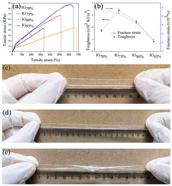
Figure 1.
The tensile processes of ionic gels with different ionic liquid concentrations: (a) stress–strain curves; (b) transformation patterns of fracture strength and toughness. Pictures of IG75% ionic gel (c) in an initial state; (d) stretched to 300%; and (e) stretched to 300% after tying.
In Figure 1b, as the proportion of ionic liquid decreased, the ductility of the EAN/F127DA ionic gel also gradually increased. This was because the proportion of ionic liquid decreased and the proportion of block copolymer increased, so more bridging structures formed between the polymer micelles, which greatly improved the ductility. However, samples with low ionic liquid contents had lower fracture strengths than other samples, indicating that the samples became “soft and tough” and were more easily stretched (requiring less stress). In this experiment, the ultimate tensile strength was also measured. The ultimate tensile ratio of the ionic gel was 2000%, and the ultimate breaking strength was 3.0 ± 0.01 MPa, which fully met the tensile property requirements of flexible strain sensors. In the graph, it can be seen that the sample performance was optimal when the proportion of ionic liquid was 75% (IG75%). The tensile performance of an ionic gel material is an important parameter to measure its ability to be used as a flexible strain sensor. The tensile performance of the EAN/F127DA ionic gel prepared in this experiment is shown in Figure 1c–e. It can be clearly seen that the EAN/F127DA ionic gel had a high tensile ratio (as shown in Figure 1d) and did not break when stretched to 300% by hand. Even if the EAN/F127DA ionic gel was knotted and stretched to 300%, no fracture occurred, indicating that EAN/F127DA ionic gel can meet the tensile property requirements of flexible strain sensors. EAN/F127DA ionic gel can also meet the electromechanical performance requirements of flexible strain sensors. (Refer to supplementary material for the mechanical and electrical performance analysis.)
In this experiment, the IG75% sample with the most prominent peak position was selected to conduct in situ small-angle X-ray scattering experiments on its stretching process (Figure 2). First, in this experiment, the one-dimensional data corresponding to the 2DSAXS image in the initial state were fitted, and the results are shown in Figure 2b. Based on the unique and characteristic peak positions of the FCC structure, it was determined that the first peak was a [1,1,1] crystal plane, the second peak was a [2,0,0] crystal plane, the third peak was a [2,2,0] crystal plane, and the fourth peak was a [3,1,1] crystal plane. The ratio between the peak positions was close to 1: : : , which was consistent with the peak position characteristics of the FCC structure [48]. The diffraction peaks in such samples are broad, indicative of a relatively poor long-range order [23]. However, the position of the peaks in the micro-region of the material we prepared exhibited high-quality long-range ordering. Please refer to S2 for the calculation of related functions.
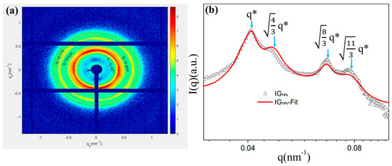
Figure 2.
IG75% ionic gel: (a) 2DSAXS peak position description; (b) corresponding peak position after fitting. Intensity is a function of the scattering vector (q) measured at room temperature for samples crosslinked at 40 °C (Δ) and fitting (line). The peak positions of the expected FCC spheres are indicated by arrows. (q* is the distinguishing q function).
In the 2DSAXS images taken during the stretching process (Figure 3a–d), an isotropic SAXS profile was observed before stretching, indicating that the microstructure was composed of randomly oriented FCC grains. Stretching the sample resulted in the appearance of six symmetrical diffraction spots, indicating that the micelles were stacked with HCP layers perpendicular to the X-ray beam. The “Six Point” image started at ε = 0.7. It was clearly observed that as the strain increased, this phenomenon became increasingly apparent. It can be inferred that the strain hardening of an ionic gel occurs under the effect of continuous stress, and greater stress is required to continue deformation. At this time, micelles are easier to stack in HCP layers [49]. It is worth noting that this transformation is reversible, as the stress in the unloaded sample (such as in the 2D SAXS image marked as “return” in Figure 3e and the corresponding curve in Figure 3f) was almost identical before and after stretching, indicating a return to the same micelle structure.
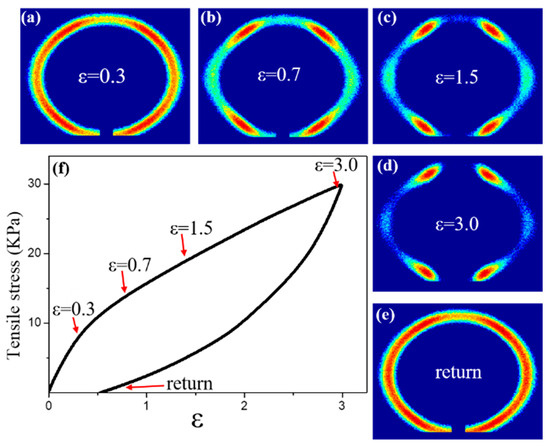
Figure 3.
The stretching recovery process of IG75% ionic gel (75% ionic liquid) below 40 °C: (a–e) 2DSAXS diagrams under different stress effects; (f) stress–strain curve.
In Figure 4b, as the strain increased, the second, third, and fourth peaks of the sample gradually disappeared, which may have been due to the influence of stress leading to changes in the microstructure. Since the plane density of the [1,1,1] plane was the highest in the FCC structure, the micelles tended to stack along the [1,1,1] plane under stress. While at low strain, the stress action was smaller than the intermolecular force, no slip occurred between the [1,1,1] planes (stretched to 15%), and the position of the peak did not shift relative to the original image. As the strain increased, the micelles on the [2,0,0] plane were stacked along the [1,1,1] crystal plane before the micelles on the [2,2,0] and [3,1,1] crystal planes (stretching to 30%). When the strain was too large (stretched to 100%), peak positions 2, 3, and 4 disappeared, indicating that the micelles were stacked according to the [1,1,1] crystal plane. In addition, it was also found that in the process of stretching the ion gel, the scattering intensity gradually decreased with an increase in strain, indicating that the degree of regularity of the micelles on the [1,1,1] plane also changed.
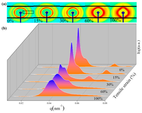
Figure 4.
Small-angle scattering of IG75% ionic gel during stretching: (a) 2D SAXS profiles (The integration area is the area where the black dashed line in Figure 4a is located); (b) SAXS intensity as a function of scattering vector q, measured at 0%, 15%, 30%, 60%, and 100%.
Figure 5 provides further evidence in this regard, showing the one-dimensional SAXS profiles of the samples before, during, and after stretching using azimuth integration. Although the hexagonal diffraction pattern in the 2D SAXS data only penetrated the strain-hardening regime, its formation began at lower strains, i.e., in the plastic deformation state, which is evident in Figure 5b. Figure 5b shows the intensity variation in the azimuth function. The earliest peak had already appeared occurring at ε = 0.3, as indicated by the arrow in Figure 5b. The peak increase rates at points 2 and 5 were significantly slower than the peak increase rates at the other four points, with the direction exactly parallel to the tensile direction. The peak intensity increased with strain, indicating a decrease in the randomly oriented region and that the FCC became a layered HCP [49,50,51,52,53,54].
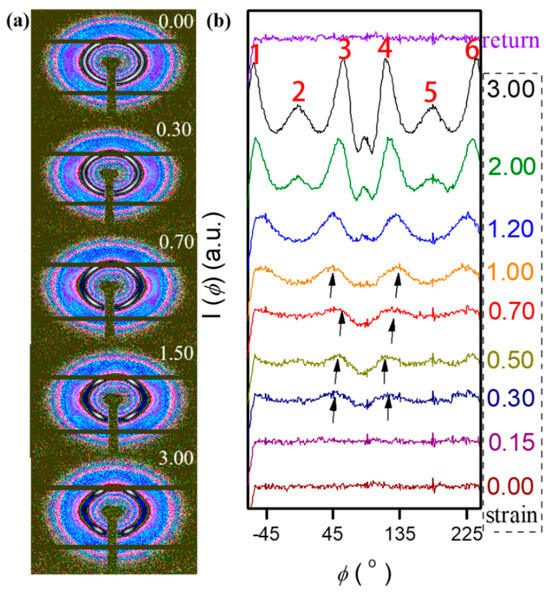
Figure 5.
(a) Two-dimensional SAXS profiles measured at the indicated strains. (b) SAXS intensity is a function of the azimuthal angle. Intensity as a function of the scattering vector, was extracted in 270°-wide sectors of the parallel image (azimuthal angle −45° to 225°).
In previous studies, several colloidal systems were reported to induce crystal structure transformation into HCP structures through shear. Under shear flow, the arrangement of HCP layers is parallel to the velocity direction in the direction of dense packing. Due to the higher planar density of the [1,1,1] surface of the face-centered cubic lattice (as shown in Figure 6a), where adjacent micelles are closer in that plane than in the [1,0,0] or [1,1,0] planes, the reason for the shear-induced FCC-to-HCP transition is easily understood. On the [111] plane, the higher interaction force between adjacent micelles can make them resist shear stress. The micelles in the [1,1,1] plane of an FCC structure have the same configuration as those in the [0,0,1] plane of an HCP structure, with the latter having a hexagonal geometric shape, forming a hexagonal scattering profile. Therefore, the transition from an FCC structure to an HCP structure is only composed of shear arrangement layers on the FCC [111] surface (as shown in Figure 6c) [55].
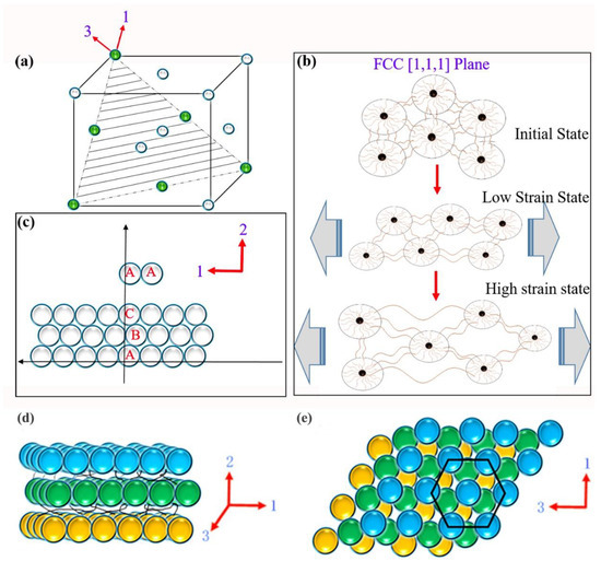
Figure 6.
(a) Schematic diagram of the FCC [1,1,1] plane. (b) Schematic diagram of the deformation of the [1,1,1] plane during stretching. (c) Cartoon showing the layered HCP structure observed during stretching. Schematic diagram of the layered HCP structure observed during stretching (d) 1,2 orientation and (e) 1,3 orientation.
The formation of HCP layers that are perpendicular to the deformation plane creates ion channels between the layers, as shown in Figure 6d,e. This configuration results in an increased “void” for ion transport in the stretching direction compared to the initial configuration of randomly oriented face-centered cubic grains. Therefore, the apparent microstructural transition in the SAXS experiments under uniaxial deformation could explain the decrease in the resistance of the ion gel upon stretching. During stretching, mechanical energy is stored in elongated bridges that connect different micelles. Therefore, when the stress is released, the bridges return to their initial state, and the micelles are pulled back to their initial position, which may explain the reversibility of the FCC-to-HCP transition observed via SAXS. This can also explain the increase in ionic resistance upon unloading due to the increase in tortuosity when a randomly oriented face-centered cubic grain morphology is restored. Of course, not all bridge structures can withstand tension, and when the bridge breaks, it is difficult to return to its original state, as reflected by the measured permanent deformation.
To further explore the energy dissipation mechanism of the ion gel, the tensile-recovery cycle test was performed on the IG75% sample. Figure 7 shows ten consecutive stretch recovery cycles at three different strains, covering three deformation states: below the yield point (strain = 10%), the plastic deformation region (strain = 50%), and the strain-hardening state (strain = 620%). Hysteresis was observed in the three regimes, indicating that there was a certain amount of internal viscoelasticity-induced friction and loss. The hysteresis was significantly larger during the first stretch–recovery cycle than in subsequent cycles, which is a typical response of gel composites known as the Mullins effect, as illustrated in Figure 7b,c. If subsequent cycles were performed with increasing strain, the hysteresis also increased accordingly, but the increase was not significant, indicating that the internal structure was not further damaged during cycling after the second cycle. Between the cycling curves, representing the dissipation of energy during cycling, and between each tensile state studied (as shown in Figure 7d), both the tensile set and dissipated energy increase by approx. one order of magnitude. The difference between cycles 2–10 and the initial cycle was large, indicating that irreversible deformation occurred, while the difference between cycles 2–10 was not large, indicating that the rate of energy dissipation slowed down in the subsequent cycles. Additionally, the tensile set increased with subsequent stretching cycles, which also indicated material fatigue due to microstructural damage. In contrast, there was no change after the first stretch–recovery cycle at low strain, which indicated that the microstructure remained unchanged after the low-strain stretch cycle, indicating that FDA/dEAN ion gel has excellent fatigue resistance, and can meet the basic requirements of a flexible strain sensor. The second cycle in the strain-hardened state could only recover to 120%, but no six-point scattering image was presented at 120%. This phenomenon was different from the previous conclusions.
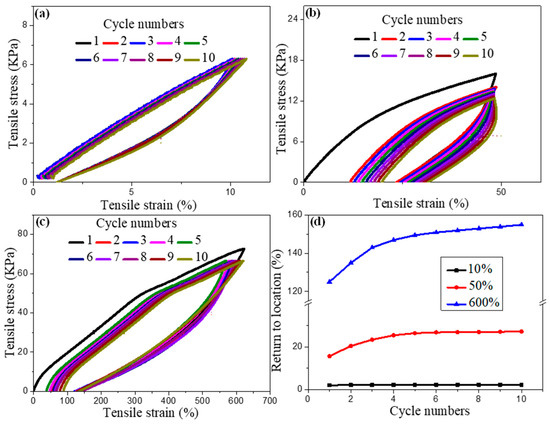
Figure 7.
Ion gel energy dissipation curves: (a) ten cycles of stretching to 10%; (b) ten cycles of stretching to 50%; (c) ten cycles of stretching to 620%; (d) ten cycles after returning to the initial position.
Some conclusions about the effect of the rate on structural relaxation were obtained by analyzing the SAXS data at different rates when stretched to the same strain. Based on the 2DSAXS image (Figure 8a), the ion gel is rate-dependent. Figure 8b shows azimuthal data for three stretching rates at ε = 0.5. The stretch rate had a large effect on this feature, with the lowest stretch rates showing little evidence of multiple peaks and the highest stretch rates having a very pronounced “double peak”. When studying the ion gel’s relaxation process, it was found that this “double-peak” characteristic disappeared quickly. At sufficiently low rates, the relaxed orientation of the micelles themselves was fast enough to merge the two peaks into one broader peak, even when flow occurred.
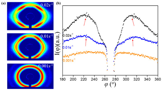
Figure 8.
Ion gel stretched to ε = 0.5 at different strain rates: (a) 2DSAXS; (b) azimuthal comparison.
Although the speed of data acquisition in the SAXS study was limited, the data collected during stretching did reveal a trend related to the stretching rate (Figure 9a,b). The orientation parameter (Figure 9a) showed almost rate-independent changes at low rates. The rate maintained an approximately linear increase, but at the highest rate (0.20 s−1), a higher ⟨P2⟩ was observed. Figure 9b summarizes the rate dependence of the orientation parameters at ε = 1.0. As the stretching rate increased, the orientation parameters increased linearly; that is, the orientation of the micelles was more pronounced at higher rates, but not higher. The higher the rate, the more obvious the micelle orientation, because with more deformation, the P2 value gradually decreased, which meant that an increase in the stretching rate only sped up the micelle orientation and did not increase the micelle orientation; that is, the degree of micelle orientation was limited.
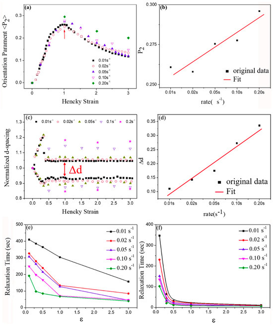
Figure 9.
IG75% ionic gel at different stretching rates: (a) variation in orientation parameter (P2), (b) rate dependence of orientation parameter (P2); (c) variation in normalized deformation parameter (d-spacing), (d) rate dependence of normalized deformation parameter d-spacing. IG75% ionic gel at different strain rates: (e) relaxation time of orientation parameter (P2); (f) relaxation time of deformation parameter (d spacing).
At lower strains, the normalized deformation parameter (d-spacing) measured in parallel and perpendicular directions (Figure 9c,d) trended similarly for all rates until ε ≈ 0.3, at which point the data deviated from the change prediction. A certain degree of deformation persisted throughout the stretching process: the deformation parameter d-spacing measured along the tensile direction was higher than the d-spacing measured along the compression direction.
The data above demonstrate the effect of the stretching rate on both parameters. For the orientation parameter, its variation with the rate was constant; that is, the orientation of a micelle did not change with the rate. For the deformation parameter, it varied with the rate; that is, the deformation of a micelle changed quickly with the rate. The previous azimuthal intensity scan also showed that the “double-peak” feature gradually became weaker when the stretching stopped. After relaxation for 300 s, the differences between data collected at different rates were largely “eliminated”. These phenomena indicate that the relaxation process of the ion gel was rate-dependent. At a sufficiently low rate, the ion gel maintained a stable microstructure, even during stretching. For the relaxation of the orientation parameter (P2) (Figure 9e), the relaxation times were investigated at all rates, and it was found that the longest average relaxation time for all rates occurred at ε = 0.1 and gradually decreased with increasing strain. The average relaxation time was the longest at the lowest stretching rate for all strains and decreased by a factor of about three when the stretching rate was increased to 0.2 s−1. For the relaxation of the deformation parameter (d-spacing) (Figure 9f), the longest relaxation time also occurred at the lowest strain. At higher strains, the relaxation time dropped sharply.
At ε = 0.3, the relaxation time dropped to 15%–30% of that at ε = 0.1, and for higher strains, the value was less than 10%. At higher strains, there was no apparent rate dependence for relaxation time. Given the limited resolution at which the SAXS data were obtained, the rapid relaxation of the deformation parameters was difficult to quantify under these conditions. While both variables showed a general tendency to accelerate relaxation at high rates, the general characteristics described earlier for the sample at 0.01 s−1 were found at all rates: (1) internal structural relaxation was slower than mechanical stress, and (2) the structural variables relaxed significantly at low strains. After 300 s of relaxation, the differences between different rates were negligible, which also verified that during the stretching process, although the stretching rates were different, the form of the microstructural changes was the same.
From the six-point scattering pattern, it was inferred that the ion gel had an HCP structure under large stress, and the stacking mode was ABAB, while after complete relaxation, it had an FCC structure, and the stacking mode was ABCABC. It can be seen that the deformation relaxation of a single micelle of the ion gel had a strong rate dependence, and that the micelle deformation relaxation speed was faster than the micelle orientation relaxation speed. This result can be seen intuitively in Figure 10. In conclusion, during the relaxation process of the ion gel, the relaxation of micelle orientation was slower than the relaxation of micelle deformation, that is; the relaxation speed of individual micelles was faster than the relaxation speed of the arrangement of the micelles during the relaxation process.
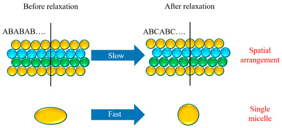
Figure 10.
Schematic diagram of the process of micelle orientation relaxation and deformation relaxation.
4. Conclusions
We have presented advanced research on the characterization of structural changes in F127 triblock copolymer ion gel during and after uniaxial extensional flow using in situ SAXS. By stopping the flow at intermediate strains, we could observe the relaxation of the structural states and mechanical stress created by the flow. Before the critical point where Hencky strain = 0.1, the relaxation of flow-induced deformation and reorientation in the microphase-separated region was retarded after stopping the flow. Under a small strain, the micellar arrangement of the ion gel was relatively intact. Conversely, high strains caused the long-range order to be disrupted. This also enabled more rapid relaxation at high strains. We also discussed the effect of the stretching rate on the ion gel microstructure and found a general trend towards shorter mean relaxation times at higher stretching rates. The flow-induced domain orientation relaxation rate was lower than the flow-induced d-spacing deformation at all rates. This material can be used as an intelligent or composite material added to coatings to help the coatings interact with the outside world. However, there may be difficulties in making thin films, such as interface bonding issues when in direct contact with the substrate, and significant impacts on the interfaces on conductivity. Future research will attempt to make progress in this area.
Supplementary Materials
The following supporting information can be downloaded at: https://www.mdpi.com/article/10.3390/coatings14050562/s1, the mechanical and electrical performance analysis. Ref. [56] is cited in Supplementary Materials.
Author Contributions
Conceptualization: N.Z.; Methodology: S.Y. and S.S.; Formal analysis and investigation: A.Z. and F.W.; Writing—original draft preparation: J.T. and S.S.; Writing—review and editing: J.T. All authors have read and agreed to the published version of the manuscript.
Funding
This research was funded by the Ningdong Base Science and Technology Innovation Development Special Project (2019NDKJLX0008), the Scientific Research Fund of the Education Department of Hunan Province (23A0111), and the High Technology Research and Development Program of Hunan Province of China (2022GK4038). The authors thank their colleagues at SAXS beamlines (BL16B) of the Shanghai Synchrotron Radiation Facility for their support and discussions.
Institutional Review Board Statement
Not applicable.
Informed Consent Statement
Informed consent was obtained from all subjects involved in the study.
Data Availability Statement
The data presented in this study are available upon request from the corresponding author. The data are not publicly available due to technical limitations.
Conflicts of Interest
Authors Shujun Yan, Angui Zhang, Fu Wang were employed by the company National Energy Group Ningxia Coal Industry Co., Ltd.; Authors Jun Tang and Nie Zhao were employed by the company Hunan Bangzer Technology Co., Ltd. The remaining author declare that the research was conducted in the absence of any commercial or financial relationships that could be construed as a potential conflict of interest.
References
- Chen, Q.; Chen, H.; Zhu, L.; Zheng, J. Engineering of Tough Double Network Hydrogels. Macromol. Chem. Phys. 2016, 217, 1022–1036. [Google Scholar] [CrossRef]
- Wang, W.; Zhang, Y.; Liu, W. Bioinspired fabrication of high strength hydrogels from non-covalent interactions. Prog. Polym. Ence 2017, 71, 1–25. [Google Scholar] [CrossRef]
- Creton, C. 50th Anniversary Perspective: Networks and Gels: Soft but Dynamic and Tough. Macromolecules 2017, 50, 8297–8316. [Google Scholar] [CrossRef]
- Bayliss, N.; Schmidt, B.V.K.J. Hydrophilic polymers: Current trends and visions for the future. Prog. Polym. Sci. 2023, 147, 101753. [Google Scholar] [CrossRef]
- Lei, Z.; Wang, Q.; Sun, S.; Zhu, W.; Wu, P. A Bioinspired Mineral Hydrogel as a Self-Healable, Mechanically Adaptable Ionic Skin for Highly Sensitive Pressure Sensing. Adv. Mater. 2017, 29, 1700321. [Google Scholar] [CrossRef] [PubMed]
- Keplinger, C.; Sun, J.Y.; Foo, C.C.; Rothemund, P.; Whitesides, G.M.; Suo, Z. Stretchable, Transparent Ionic Conductors. Science 2013, 341, 984–987. [Google Scholar] [CrossRef]
- Xu, C.; Li, B.; Xu, C.; Zheng, J. A novel dielectric elastomer actuator based on compliant polyvinyl alcohol hydrogel electrodes. J. Mater. Sci. Mater. Electron. 2015, 26, 9213–9218. [Google Scholar] [CrossRef]
- Lei, Z.; Wu, P. A supramolecular biomimetic skin combining a wide spectrum of mechanical properties and multiple sensory capabilities. Nat. Commun. 2018, 9, 1134. [Google Scholar] [CrossRef]
- Dechnarong, N.; Kamitani, K.; Cheng, C.H.; Masuda, S.; Takahara, A. In Situ Synchrotron Radiation X-ray Scattering Investigation of a Microphase-Separated Structure of Thermoplastic Elastomers under Uniaxial and Equi-Biaxial Deformation Modes. Macromolecules 2020, 53, 8901–8909. [Google Scholar] [CrossRef]
- Dechnarong, N.; Kamitani, K.; Cheng, C.H.; Masuda, S.; Takahara, A. Microdomain structure change and macroscopic mechanical response of styrenic triblock copolymer under cyclic uniaxial and biaxial stretching modes. Polym. J. 2021, 53, 703–712. [Google Scholar] [CrossRef]
- Heck, M.; Schneider, L.; Müller, M.; Wilhelm, M. Diblock Copolymers with Similar Glass Transition Temperatures in Both Blocks for Comparing Shear Orientation Processes with DPD Computer Simulations. Macromol. Chem. Phys. 2018, 219, 1700559. [Google Scholar] [CrossRef]
- Florez, S.; Muñoz, M.A.E.; Santamaría, A. Basic rheological features of block polyurethane solutions: Entanglements, crystallization, and gelation. J. Rheol. 2005, 49, 313–325. [Google Scholar] [CrossRef]
- Meuler, A.J.; Hillmyer, M.A.; Bates, F.S. Ordered Network Mesostructures in Block Polymer Materials. Am. Chem. Soc. 2009, 42, 7221–7250. [Google Scholar] [CrossRef]
- Meins, T.; Hyun, K.; Dingenouts, N.; Fotouhi Ardakani, M.; Struth, B.; Wilhelm, M. New Insight to the Mechanism of the Shear-Induced Macroscopic Alignment of Diblock Copolymer Melts by a Unique and Newly Developed Rheo–SAXS Combination. Macromolecules 2012, 45, 455–472. [Google Scholar] [CrossRef]
- Abuzaina, F.M.; Patel, A.J.; Mochrie, S.; Narayanan, S.; Sandy, A.; Garetz, B.A.; Balsara, N.P. Structure and Phase Behavior of Block Copolymer Melts near the SphereCylinder Boundary. Macromolecules 2015, 38, 7090–7097. [Google Scholar] [CrossRef]
- Silva, J.; Andrade, R.; Huang, R.; Liu, J.; Cox, M.; Maia, J.M. Rheological behavior and structure development in thermoplastic polyurethanes under uniaxial extensional flow. J. Non Newton. Fluid Mech. 2015, 222, 96–103. [Google Scholar] [CrossRef]
- Mao, R.; Mccready, E.M.; Burghardt, W.R. Structural response of an ordered block copolymer melt to uniaxial extensional flow. Soft Matter 2014, 10, 6198–6207. [Google Scholar] [CrossRef] [PubMed]
- Huang, Q.R.; Rasmussen, H.K. The transition between undiluted and oligomer-diluted states of nearly monodisperse polystyrenes in extensional flow. Rheol. Acta Int. J. Rheol. 2017, 56, 719–727. [Google Scholar] [CrossRef][Green Version]
- Ogura, K.; Wagner, M.H. Rheological characterization of cross-linked poly(methyl methacrylate). Rheol. Acta 2013, 52, 753–765. [Google Scholar] [CrossRef]
- Lu, W.; Goodwin, A.; Wang, Y.; Yin, P.; Wang, W.; Zhu, J.; Wu, T.; Lu, X.; Hu, B.; Hong, K.; et al. All-acrylic superelastomers: Facile synthesis and exceptional mechanical behavior. Polym. Chem. 2018, 9, 160–168. [Google Scholar] [CrossRef]
- Lv, C.; Wang, R.; Gao, J.; Ding, N.; Dong, S.; Nie, J.; Xu, J.; Du, B. PAA-b-PPO-b-PAA triblock copolymers with enhanced phase separation and inverse order-to-order phase transition upon increasing temperature. Polymer 2019, 185, 121982. [Google Scholar] [CrossRef]
- Gong, J.P. Materials both Tough and Soft. Science 2014, 344, 161–162. [Google Scholar] [CrossRef] [PubMed]
- López-Barrón, C.R.; Chen, R.; Wagner, N.J.; Beltramo, P.J. Self-Assembly of Pluronic F127 Diacrylate in Ethylammonium Nitrate: Structure, Rheology, and Ionic Conductivity before and after Photo-Cross-Linking. Macromolecules 2016, 49, 5179–5189. [Google Scholar] [CrossRef]
- Zhao, X. Multi-scale multi-mechanism design of tough hydrogels: Building dissipation into stretchy networks. Soft Matter 2014, 10, 672–687. [Google Scholar] [CrossRef] [PubMed]
- Vedadghavami, A.; Minooei, F.; Mohammadi, M.H.; Khetani, S.; Rezaei Kolahchi, A.; Mashayekhan, S.; Sanati-Nezhad, A. Manufacturing of hydrogel biomaterials with controlled mechanical properties for tissue engineering applications. Acta Biomater. 2017, 62, 42–63. [Google Scholar] [CrossRef] [PubMed]
- Beda, T. An approach for hyperelastic model-building and parameters estimation a review of constitutive models. Eur. Polym. J. 2014, 50, 97–108. [Google Scholar] [CrossRef]
- Meng, F.; Pritchard, R.H.; Terentjev, E.M. Stress relaxation, dynamics and plasticity of transient polymer networks. Macromolecules 2016, 49, 2843–2852. [Google Scholar] [CrossRef]
- Rose, S.; Dizeux, A.; Narita, T.; Hourdet, D.; Marcellan, A. Time dependence of dissipative and recovery processes in nanohybrid hydrogels. Macromolecules 2013, 46, 4095–4104. [Google Scholar] [CrossRef]
- Green, M.S.; Tobolsky, A.V. A New Approach to the Theory of Relaxing Polymeric Media. J. Chem. Phys. 2004, 14, 80–92. [Google Scholar] [CrossRef]
- Tamate, M.W.; Hashimoto, K.; Li, X.; Shibayama, M.; Watanabe, M. Effect of ionic liquid structure on viscoelastic behavior of hydrogen-bonded micellar ion gels. Polym. Int. J. Sci. Technol. Polym. 2019, 178, 121694. [Google Scholar]
- Walter, R.; Walkenhorst, R.; Smith, M.; Selser, J.C.; Bogoslovov, R. The role of polymer melt viscoelastic network behavior in lithium ion transport for PEO melt/LiClO 4 SPEs: The. J. Power Sources 2000, 89, 168–175. [Google Scholar] [CrossRef]
- Mao, Y.; Lin, S.; Zhao, X.; Anand, L. A large deformation viscoelastic model for double-network hydrogels. Pergamon 2017, 100, 103–130. [Google Scholar] [CrossRef]
- Cheng, J.; Jia, Z.; Li, T. A constitutive model of microfiber reinforced anisotropic hydrogels: With applications to wood-based hydrogels. J. Mech. Phys. Solids 2020, 138, 103893. [Google Scholar] [CrossRef]
- Liu, D.; Ma, S.; Yuan, H.; Markert, B. Computational modelling of poro-visco-hyperelastic effects on time-dependent fatigue crack growth of hydrogels. Int. J. Plast. 2022, 155, 103307. [Google Scholar] [CrossRef]
- Xing, Z.; Li, Z.; Lu, H.; Fu, Y.Q. Self-assembled topological transition via intra- and inter-chain coupled binding physical hydrogel towards mechanical toughening. Polym. Int. J. Sci. Technol. Polym. 2021, 235, 124268. [Google Scholar] [CrossRef]
- Javadi, M.H.; Darijani, H.; Niknafs, M. Constitutive modeling of visco-hyperelastic behavior of double-network hydrogels using long-term memory theory. J. Appl. Polym. Sci. 2020, 138, 49894. [Google Scholar] [CrossRef]
- Mau, B.; Erfkamp, J.; Guenther, M.; Wallmersperger, T. Determination of material parameters for a multiphasic modeling of hydrogels. PAMM 2019, 19, e201900216. [Google Scholar] [CrossRef]
- Kwon, J.H.; Kim, Y.M.; Moon, H.C. Porous Ion Gel: A Versatile Ionotronic Sensory Platform for High-Performance, Wearable Ionoskins with Electrical and Optical Dual Output. ACS Nano 2021, 15, 15132–15141. [Google Scholar] [CrossRef]
- Feng, D.; Niu, Z.; Yang, J.; Xu, W.; Liu, S.; Mao, X.; Li, X. Flexible artificial synapse with relearning function based on ion gel-graphene FET—ScienceDirect. Nano Energy 2021, 90, 106526. [Google Scholar] [CrossRef]
- Chae, K.; Cuong, N.D.; Ryu, S.; Yeom, D.I.; Ahn, Y.H.; Lee, S.; Park, J.Y. Electrical properties of ion gels based on PVDF-HFP applicable as gate stacks for flexible devices. Curr. Appl. Phys. Off. J. Korean Phys. Soc. 2018, 18, 500–504. [Google Scholar] [CrossRef]
- Liu, W.; Sun, J.; Qiu, W.; Chen, Y.; Yang, J. Sub-60 mV per decade switching in ion-gel-gated In–Sn–O transistors with a nano-thick charge trapping layer. Nanoscale 2019, 11, 21740–21747. [Google Scholar] [CrossRef] [PubMed]
- Russo, G.; Rossella Delpiano, G.; Carucci, C.; Grosso, M.; Dessì, C.; Söderman, O.; Lindman, B.; Monduzzi, M.; Salis, A. Tuning Pluronic F127 phase transitions by adding physiological amounts of salts: A rheology, SAXS, and NMR investigation. Eur. Polym. J. 2024, 204, 112714. [Google Scholar] [CrossRef]
- Albano, J.M.R.; Grillo, D.; Facelli, J.C.; Ferraro, M.B.; Pickholz, M. Study of the Lamellar and Micellar Phases of Pluronic F127: A Molecular Dynamics Approach. Processes 2019, 7, 606. [Google Scholar] [CrossRef]
- Cellesi, F.; Tirelli, N.; Hubbell, J.A. Materials for cell encapsulation via a new tandem approach combining reverse thermal gelation and covalent crosslinking. Macromol. Chem. Phys. 2002, 203, 1466–1472. [Google Scholar] [CrossRef]
- Sentmanat, M.L. Miniature universal testing platform: From extensional melt rheology to solid-state deformation behavior. Rheol. Acta 2004, 43, 657–669. [Google Scholar] [CrossRef]
- Wang, Y.; Boukany, P.; Wang, S.Q.; Wang, X. Elastic Breakup in Uniaxial Extension of Entangled Polymer Melts. Phys. Rev. Lett. 2007, 99, 237801. [Google Scholar] [CrossRef] [PubMed]
- McCready, E.M.; Burghardt, W.R. In Situ SAXS Studies of Structural Relaxation of an Ordered Block Copolymer Melt Following Cessation of Uniaxial Extensional Flow. Macromolecules 2015, 48, 264–271. [Google Scholar] [CrossRef]
- López-Barrón, C.R.; Chen, R.; Wagner, N.J. Ultrastretchable Iono-Elastomers with Mechanoelectrical Response. ACS Macro Lett. 2016, 5, 1332–1338. [Google Scholar] [CrossRef]
- Lopez-Barron, C.R.; Porcar, L.; Eberle, A.P.R.; Wagner, N.J. Dynamics of Melting and Recrystallization in a Polymeric Micellar Crystal Subjected to Large Amplitude Oscillatory Shear Flow. Phys. Rev. Lett. 2012, 108, 258301. [Google Scholar] [CrossRef]
- Jiang, J.; Malal, R.; Li, C.; Lin, M.Y.; Cohn, D. Rheology of Thermoreversible Hydrogels from Multiblock Associating Copolymers. Macromolecules 2008, 41, 3646–3652. [Google Scholar] [CrossRef]
- Jiang, J.; Li, C.; Lombardi, J.; Colby, R.H.; Rigas, B.; Rafailovich, M.H.; Sokolov, J.C. The effect of physiologically relevant additives on the rheological properties of concentrated Pluronic copolymer gels. Polymer 2008, 49, 3561–3567. [Google Scholar] [CrossRef]
- McMullan, J.M.; Wagner, N.J. Directed self-assembly of suspensions by large amplitude oscillatory shear flow. J. Rheol. 2009, 53, 575–588. [Google Scholar] [CrossRef]
- Lee, C.W.; Porcar, L.; Rogers, S.A. Unveiling Temporal Nonlinear Structure-Rheology Relationships under Dynamic Shearing. Polymers 2019, 11, 1189. [Google Scholar] [CrossRef] [PubMed]
- Wu, Y.L.; Derks, D.; Van Blaaderen, A.; Imhof, A. Melting and crystallization of colloidal hard-sphere suspensions under shear. Proc. Natl. Acad. Sci. USA 2009, 106, 10564–10569. [Google Scholar] [CrossRef] [PubMed]
- Lopez-Barron, C.R.; Li, D.; Wagner, N.J.; Caplan, J.L. Triblock Copolymer Self-Assembly in Ionic Liquids: Effect of PEO Block Length on the Self-Assembly of PEO–PPO–PEO in Ethylammonium Nitrate. Macromolecules 2014, 47, 7484–7495. [Google Scholar] [CrossRef]
- Burger, C.; Hsiao, B.S.; Chu, B. Preferred Orientation in Polymer Fiber Scattering. Polym. Rev. 2010, 50, 91–111. [Google Scholar] [CrossRef]
Disclaimer/Publisher’s Note: The statements, opinions and data contained in all publications are solely those of the individual author(s) and contributor(s) and not of MDPI and/or the editor(s). MDPI and/or the editor(s) disclaim responsibility for any injury to people or property resulting from any ideas, methods, instructions or products referred to in the content. |
© 2024 by the authors. Licensee MDPI, Basel, Switzerland. This article is an open access article distributed under the terms and conditions of the Creative Commons Attribution (CC BY) license (https://creativecommons.org/licenses/by/4.0/).