Article

Investigation of the Structure and Properties of MoS2 Coatings Obtained by Electrospark Alloying

by
Oksana Haponova
1,2,*,
Viacheslav Tarelnyk
3,
Tomasz Mościcki
1,
Nataliia Tarelnyk
3,
Joanna Półrolniczak
4,
Oleksandr Myslyvchenko
5,
Bogusława Adamczyk-Cieślak
6 and
Joanna Sulej-Chojnacka
4
1
Department of Experimental Mechanics, Institute of Fundamental Technological Research Polish Academy of Sciences, Pawińskiego 5B, 02-106 Warsaw, Poland
2
Applied Material Science and Technology of Constructional Materials Department, Sumy State University, Kharkivska 116, 40007 Sumy, Ukraine
3
Technical Service Department, Sumy National Agrarian University, H. Kondratiieva 160, 40021 Sumy, Ukraine
4
Łukasiewicz–Poznań Institute of Technology, Ewarysta Estkowskiego 6, 61-755 Poznań, Poland
5
Physical Chemistry of Inorganic Materials Department, Frantsevich Institute for Problems of Materials Science NASU, Omeliana Pritsaka 3, 04060 Kyiv, Ukraine
6
Division of Materials Design, Warsaw University of Technology, Wołoska 141, 02-507 Warsaw, Poland
*
Author to whom correspondence should be addressed.
Coatings 2024, 14(5), 563; https://doi.org/10.3390/coatings14050563
Submission received: 5 April 2024 / Revised: 25 April 2024 / Accepted: 29 April 2024 / Published: 1 May 2024
(This article belongs to the Special Issue Functional Surface Modification Using Concentrated Energy Flows)

Abstract

:
Electrospark coatings alloyed with MoS2 have been studied. The coatings were obtained by the following two strategies: the first consisted of pre-applying molybdenum disulfide to the treated surface and alloying with a molybdenum electrode (Mo + MoS2 coating); the second consisted of applying a paste with a sulfur content of 33.3% to the treated surface and alloying with a molybdenum electrode (Mo + S coating). The structure, phase composition, and tribological properties of the coatings were investigated. The coatings have a complex structure consisting of an upper soft layer, a hardened white layer, a diffusion zone, and a substrate. Element analysis and cross-sectional hardness changes indicated that element diffusion occurred at the coating/substrate interface. The phase composition of the coatings is represented by BCC and FCC solid solutions on Fe, and MoS2 is also detected. In Mo + S coatings, the molybdenum disulfide on the surface is about 8%; in Mo + MoS2 coatings, it is 27%–46%. The obtained coatings show very good tribological properties compared to molybdenum ESA coatings. The frictional forces and coefficients are reduced by a factor of 10 and 40, depending on the test conditions.

1. Introduction

Severe wear and tear of connected parts in friction units results in loss of kinetic accuracy of mechanisms, violation of machine working space tightness, disruption of normal lubrication, etc. As a result, both the serviceability and productivity of the friction unit are reduced, resulting in a reduction in product quality [1,2]. This applies to a range of friction elements in dynamic equipment. Examples include support and thrust bearings for high-speed turbomachines [3], contact and non-contact end seals [4], sockets [5], etc., which operate with lubricant under heavy conditions, namely, at increased loads and speeds in aggressive environments, elevated temperatures, etc. The wear and tear associated with the operation of the friction parts of the machine is the reason for the reduction in the life of the assembly [6].
There are currently a large number of surface modification methods, classified according to specific characteristics, for imparting certain functional properties to working surfaces. However, most of the methods are usually characterized by high equipment costs and, sometimes, long deposition times. In addition, some of them cannot be used to repair parts, which limits their application. Therefore, the technical problem, which consists of increasing the wear resistance and durability of the pumping equipment friction parts by creating new technologies for the surface treatment of the anti-friction parts, is very relevant and requires further research. Those should meet the modern requirements of mechanical engineering and be able to operate without lubrication, as well as be inexpensive.
As is known [7], coating materials with increased antifriction properties should be characterized by low microhardness and high plasticity. Such materials as copper and brass, as well as metal sulfides, in particular molybdenum disulfide (MoS2), have corresponding properties. The coatings, which contain molybdenum sulfides, are distinguished by their antifriction properties [8,9]. The MoS2 coating’s tribological properties are conditioned by its layered structure with weak van der Waals forces.
The anti-wear characteristics of the MoS2 coating depend on the method of its application and distribution on the contacting surfaces of the products to be coated. The existing methods of coating with MoS2 differ in diversity. The choice of method is determined by the operating conditions of the assembly units and friction mechanisms, the structural features of the parts being covered, the accessibility of surfaces, and the necessary technical capabilities.
The most common process for forming molybdenum disulfide on the surfaces of friction pair parts is mechanical application by rubbing the MoS2 powder into the surface or by introducing it into the composition of the lubricating material that is applied to the surface. The coatings obtained by rubbing the powder have a thickness of about 1 μm. Therefore, they have a short service life. In [10], a vibration coating method is proposed.
It should be noted that mechanically applied coatings are thin and wear out quickly. Therefore, researchers from all over the world are solving the problem of creating composite materials of the “coating-substrate” type.
To obtain thin films of transition metal dichalcogenides (TMDs) industrially, two main types of methods can be used, namely, chemical vapor deposition (CVD) and physical vacuum deposition (PVD) based on ion-sputtering coating. They allow obtaining MoS2 films with crystallite sizes of 10 to 1 μm [11]. The TMD films of such materials as MoS2 [12], WS2 [13], and WSe2 [14] were obtained by PVD methods. The main disadvantage of the chemical deposition methods is the high process temperatures [15]. Physical vapor deposition (PVD) has become the most common method of MoS2 coating deposition [16,17].
In the literature, there is information on the production of the transition metal dichalcogenides by the methods of laser cladding [18], electrochemical deposition [19], thermal spraying [20], and electrospark alloying (ESA) [21,22].
During the ESA process, there is diffusion and deposition of alloying electrode material onto the metal being processed. In the course of the ESA process, a strong metallurgical bond is formed between the coating and the substrate. This is the main reason for high adhesion. The strength of the “coating-substrate” adhesion created with the ESA process is considered one of the best, as compared to other methods [23]. Another advantage is the short time duration and high pulse current. During the process, the material of the substrate is practically not heated. It occurs owing to the locality of the processing and leads to minor changes in the microstructure of the substrate or to their absence at all [24]. In addition, the ESA coatings always consist of unique structures (nano-, subfine-crystalline, amorphous ones, etc.) due to a significant cooling rate of about 105 to 106 °K/s, which can improve the properties of the coatings [25,26]. Moreover, the ESA process is also a simple, cost-effective, and environmentally safe technology that is used in mechanical engineering, chemistry, medicine, aerospace, military industry, etc. [27,28].
Thus, in work [29], Cu/Cu-MoS2 coatings were obtained by electrospark deposition on high-speed steel using an electrode made of copper tubes filled with MoS2. However, this method requires the manufacture of a special electrode that is labor-intensive and does not provide the required quality of the working surface. The tribotechnical properties of Ni-MoS2 coatings obtained by the ESA method were investigated in [30]. The Ni-MoS2 electrode was manufactured by the spark plasma sintering (SPS) method using a mixture of argon-atomized nickel powder (50 wt. %) and MoS2 powder (50 wt. %).
The results of the studies published in the literature indicate that the ESA method has a promising perspective for obtaining coatings from transition metal dichalcogenides. However, ESA technologies have to be studied and improved to ensure the formation of a coating with the specified parameters for the best operation of the equipment. Therefore, the aim of the presented work is to improve the synthesis technology of the MoS2-based self-lubricating coatings obtained by energy conservation and inexpensive ESA methods and to study the structures and tribotechnical properties of the coatings.

2. Materials and Methods

The critical parts of the equipment are made of different grades of steel. For example, shafts and gears are made of low- and medium-carbon steels, such as C20 steel and C40 steel, with carbon contents of 0.2% and 0.4%, respectively. Impellers, vanes, sealing rings, etc., which work under wear conditions in aggressive environments and at elevated temperatures, are made of special austenitic steels such as AISI 321 steel. Therefore, different grades of steel were used in the research.
The electrospark alloying process was carried out with a molybdenum electrode tool manufactured by the SPS method according to the technology described in [31] using the Elytron–52A unit. The treatment modes controlled by a tumbler were set to discharge energies (Wp) of 0.13, 0.55, and 3.4 J. The capacity of the capacitor battery, the output voltage, and the oscillation frequency of the electromagnetic vibrator were as shown in Table 1. The productivity of the treatment was 1 min/cm2.
For the study, samples measuring 10 cm× 8 cm × 8 cm were made. Samples before and after ESA are shown in Figure 1. The surface roughness of the samples before treatment was Ra = 0.5 µm.
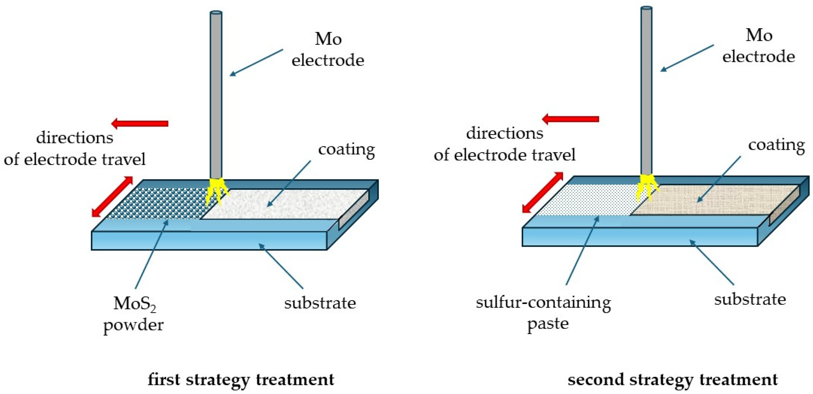
Two strategies for the treatment of sulfomolybdenation were studied (Figure 2). The first one consisted of a preliminary application of the molybdenum disulfide powder onto the treated surface and alloying it with a molybdenum electrode tool. The second one consisted of applying a paste with a sulfur content of 33.3% to the treated surface and alloying it with a molybdenum electrode tool.
After the ESA process, the surface roughness was determined using a profilograph-profilometer by taking and processing the profilograms.
The metallographic analysis of the coatings was performed using optical and scanning electron microscopes according to the standard methods. The thicknesses of the layers formed and their continuity were determined by the metallographic method. Statistical methods were used. To study the distribution of the elements along the depth of the layer, a local micro-X-ray spectral analysis was carried out using a SEO-SEM Inspect S50-B scanning electron microscope equipped with an AZtecOne energy dispersive spectrometer with an X-MaxN20 detector (manufacturer: Oxford Instruments plc, Oxford, UK). To analyze the Vickers hardness distribution in the surface layer along the depth of the specimen from the surface, a NOVA 330/360 hardness tester (manufactured by INNOVATEST Europe BV, Maastricht, The Netherlands) was used standard methodology. The load was 20 g.
The X-ray studies were carried out with CoKα radiation. A D8 Advance X-ray diffractometer (Bruker AXS, Karlsruhe, Germany) was used for the study. The diffractograms were taken through step-by-step scanning. The scanning step was 0.050, and the exposure time at a point was 3 s. The diffractograms have been processed using a PowderCell 2.4 program for the full-profile analysis of X-ray spectra from a mixture of the polycrystalline components. The phase composition was determined at the surface and at a distance of 15 µm from the surface after pre-polishing.
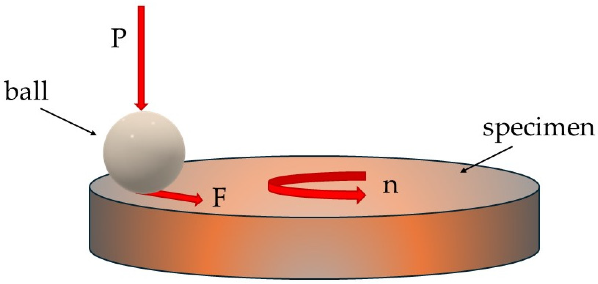
The tribological properties of the formed surface layer were determined on the T-21 tester in accordance with the tribological standard DIN-50324: 1992-07 Tribology “Testing of friction and wear tests for sliding friction of solids” by the ball-disk scheme (Figure 3). The specimens tested on the tester had a size of Ø 25 × 6 mm. The tests had been carried out while the steel ball traveled a friction path of L = 4000 m under a load of P = 20 N and of L = 1000 m under a load of P = 40 N. The diameter of the ball was 10 mm, and the material of the ball was 10Cr6. In the process of research, the following operating parameters of the tester were used: rotation speed ω was 360 rpm; loadings P were 20 and 40 N.
During the tests, the friction force F and the coefficient of friction μ were determined.
Table 2 represents a series of specimens for the wear resistance tests. For comparison, we tested the specimens without processing, the specimens that have been ESA-processed by a molybdenum electrode, and the ones processed according to the two proposed processing modes.

3. Results

There has been investigation of the structural and phase states of the coatings obtained on the surface of AISI 321 steel using the ESA technology performed by a Mo-electrode with the preliminary application of the MoS2 powder on the surface being coated (first strategy treatment).
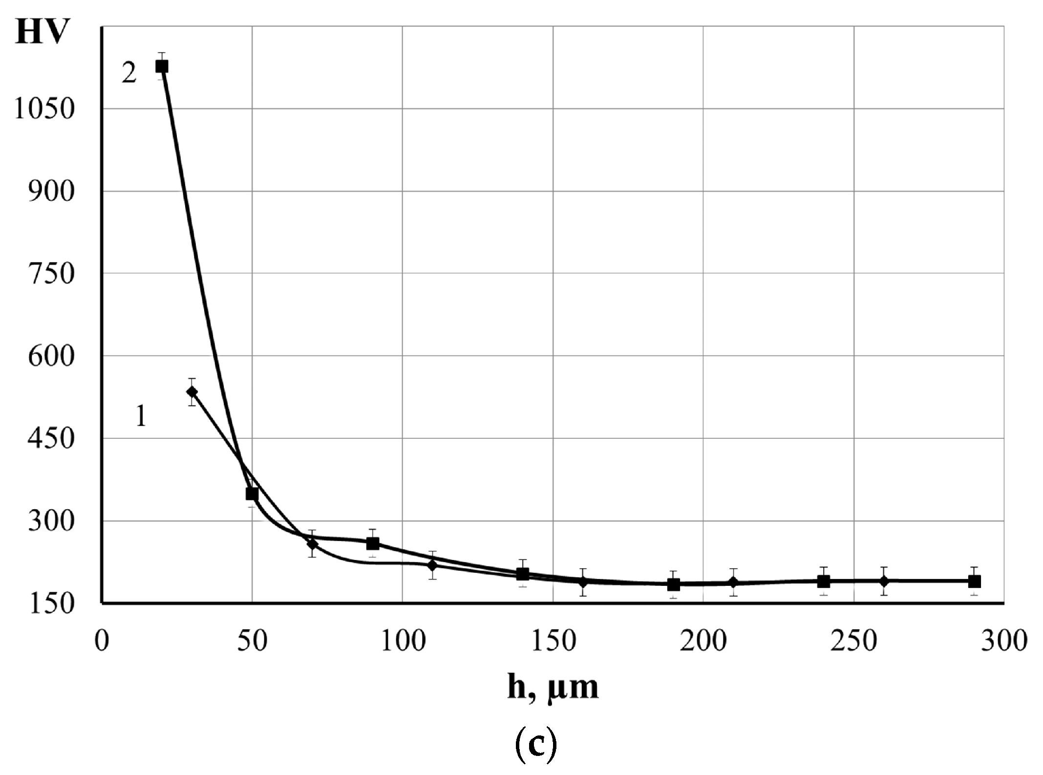
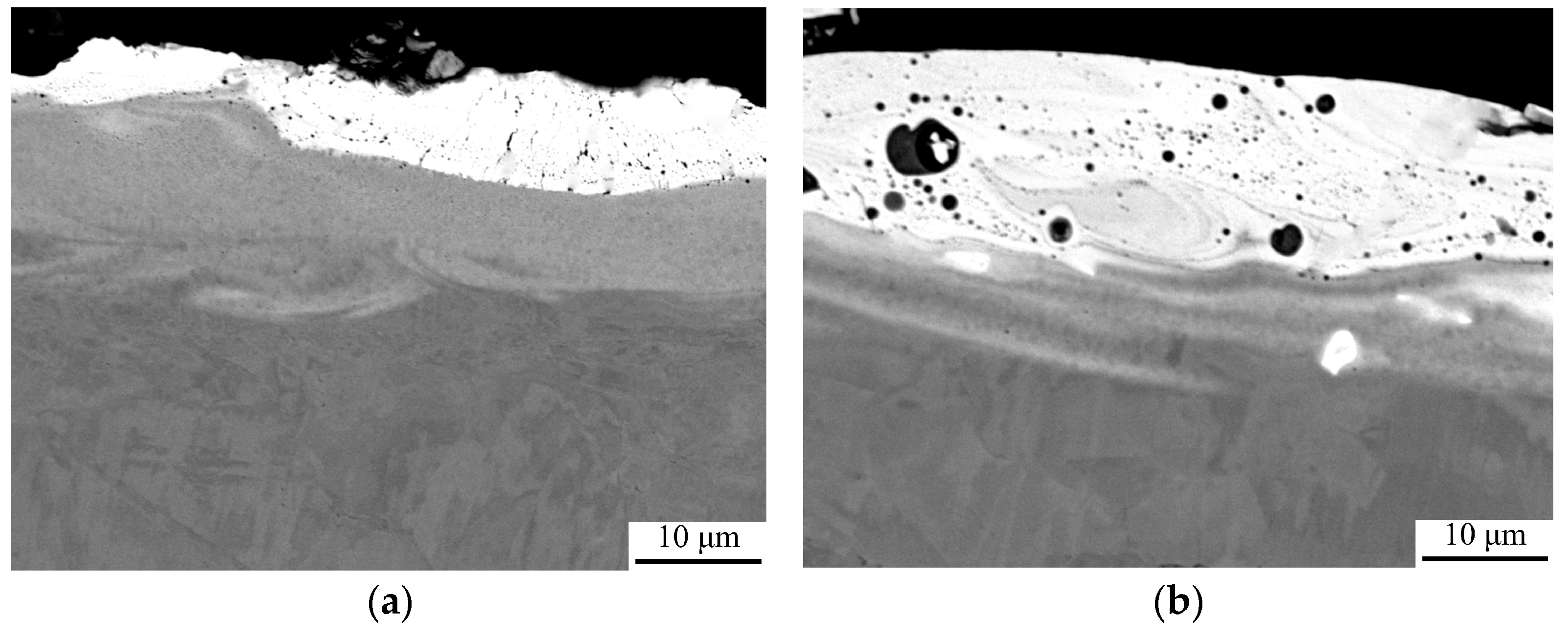
The metallographic analysis has shown (Figure 4) that on the surface, there was a “dark” layer consisting of molybdenum disulfide powder, which had been applied before the ESA process, and molybdenum itself as a material of the electrode tool. Thereafter, there is a strengthened “white” layer. Its thickness is 20 ÷ 30 and 50 ÷ 60 μm, while hardness is HV 534 and HV 1127, respectively, for the specimens after the ESA processes with the discharge energies of 0.55 and 3.4 J (Table 3, Figure 4). Due to its crumbling, the hardness of the “dark” layer could not be determined.
It should be noted that the pre-applied molybdenum disulfide powder significantly improves the ESA process (there is no sticking or adhesion of the electrode tool to the surface of the specimen). Due to the above, the roughness of the formed layer has been significantly reduced compared to samples after molybdation but without MoS2 pre-deposition [32].
Electron microscopic studies of backscattered (reflected) electrons (BSE) made it possible to determine the structure and qualitative distribution of the elements in the coating (Figure 5 and Figure 6). In the drawings, the coating zones are clearly visible. Those are the upper “dark” layer, the “white” strengthened layer, the diffusion zone, and the substrate. With increasing discharge energy, the white layer is characterized by the presence of vortex-like formations due to the Marangoni–Gibbs effect [33]. In addition, according to the results of the local X-ray spectral analysis, the strengthened layer is saturated with molybdenum. The amount of molybdenum gradually diminishes from the surface to the substrate (Figure 6). Therefore, in the diffusion zone, there is a mutual penetration of the component elements of the coating and the substrate, which ensures the high adhesion strength of the coating to the substrate.
It is known that diffusion in metals under the pulsed action of concentrated energy flows is several times higher than under continuous isothermal action. The growth of atomic mobility is associated with the creation of non-equilibrium vacancies, the effect of shear deformation, and the appearance of molten areas in the surface layers of the treated materials. When a surface is treated with the ESA method at higher discharge energy levels, the mobility of the atoms is intensified, and the temperature in the contact zone rises. Therefore, the diffusion zone is more pronounced when the substrate is treated in more stringent ways. The diffusion zone is well identified by electron microscopy and micro-X-ray spectral analysis. At ESA with a discharge energy of 3.4 J, there are no hard boundaries at the coating-substrate interface (Figure 5), and the molybdenum concentration changes smoothly from the surface to the substrate (Figure 6).
It should be noted that in the “white” layer, with an increase in the discharge energy, there is an increase in the number of pores and a change in their shape. The pores have been distributed evenly and taken on rounded shapes. The effect of porosity on the strength and tribotechnical parameters of coatings is well described in [34]. As is known [35], the availability of porosity is desirable for sealing, working-in, and self-lubricating coatings. Due to porosity, the coatings hold lubricant well on the working surface, so they can operate in conditions of insufficient lubrication. Moreover, molybdenum disulfide is an excellent lubricant, and the obtained coatings can be classified as self-lubricating ones with low rates of wear.
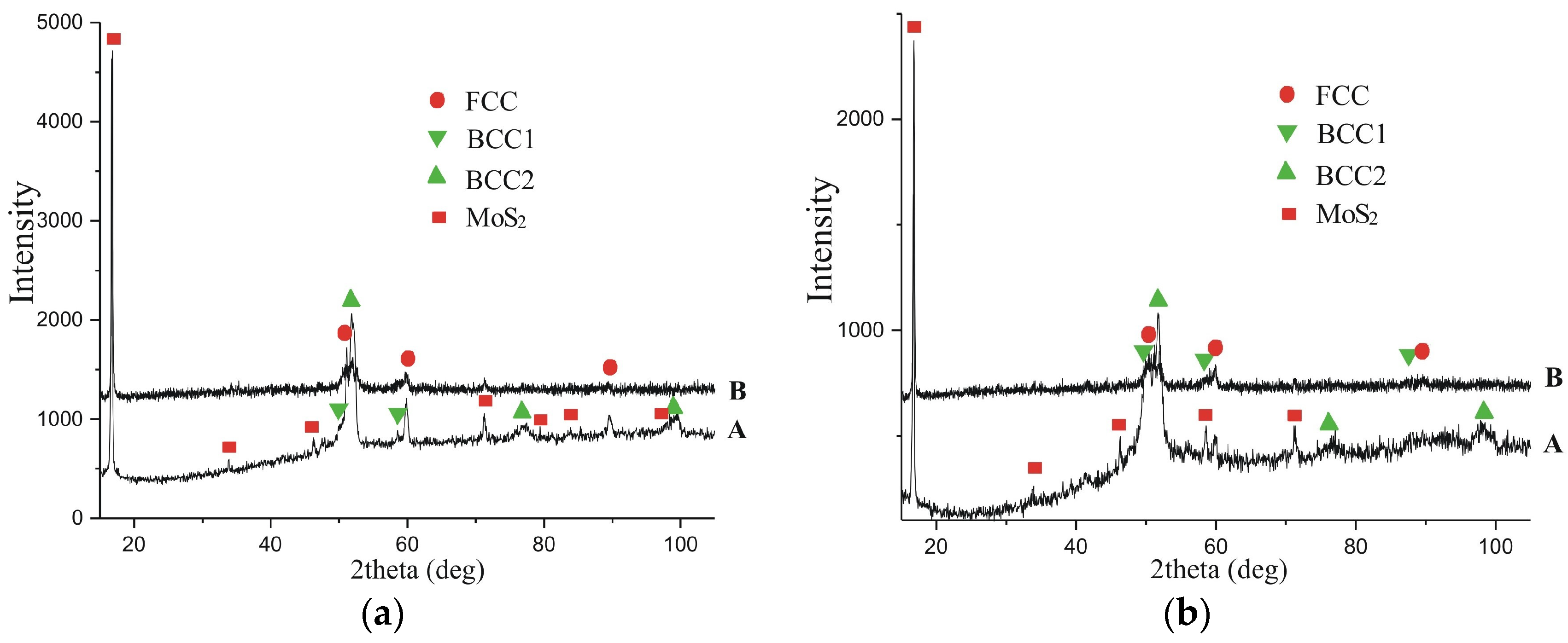
The studies have shown that the phase composition of the coating surface is represented by two solid solutions with BCC crystal structures that differ in lattice periods (Figure 7, Table 4), the FCC solid solution, namely, austenite, and molybdenum disulfide. The lattice parameters of the BCC phases were slightly larger than the lattice parameter of pure α-Fe (0.249 nm) [36]. Therefore, it can be assumed that the BCC phases are the solid solutions of molybdenum substitution in iron, since according to [37], Fe and Mo form the limited solid solutions, and the sizes of molybdenum atoms are larger than the sizes of iron. In addition, according to the results of the local microanalysis, it is possible to mix electrode materials during the formation of the ESA coatings. This can result in alloying the solid solutions found in the surface layers with alloying elements of the substrate, namely, AISI 321 steel. As shown in [38], non-equilibrium phases were formed during the ESA process. These phases are close to the amorphous state due to the accelerated cooling. In the coating, the availability of about 25% of austenite is obviously due to mixing the substrate (austenitic steel) with the coating. After obtaining the diffraction pattern from the surface, we ground off 15 microns and obtained the diffraction pattern again. The qualitative phase composition has not changed (Figure 7); MoS2 is present throughout the volume of the coating. Due to the low intensity of the diffraction lines, it was not possible to quantify the content of the phase components.
It should be noted that 27%–46% of MoS2 is found on the coating. This would obviously have a positive effect on the tribological properties of the treated surfaces. However, as the discharge energy is raised, the amount of MoS2 phase diminishes. The probable reason for the reduction in the amount of molybdenum disulfide on the surface could be its uniform distribution in the coating, which has a higher thickness and volume for the same thickness of MoS2 layer before ESA. As a result of ESA with increased discharge energy, there is intensive mixing of the anode, cathode, and MoS2 materials.
The structural phase state of MoS2-containing coatings on a steel substrate for construction and austenitic steels was also investigated. The coatings were produced using the second strategy treatment. As noted, it consisted of applying a paste with a sulfur content to the treated surface and alloying it with a molybdenum electrode tool.
There has been a study of the microstructures of the coatings on C40 steel (Figure 8). Such a coating consists of four zones: the upper loose layer having a low hardness of HV 111.2 to 204.0, the so-called “white” strengthened layer with HV 514.7 to 547.4 for Wp = 0.13 J and HV 1059.6 to 1073.1 for Wp = 3.4 J, the diffusion zone, and the substrate. In Table 5, the parameters of the obtained layers are summarized.
It is assumed that the “white” layer is formed from the liquid phase when mixing it with the base and while interpenetrating diffusion. As a rule, it consists of alloying electrode material and elements of the interelectrode medium. The diffusion zone is formed due to diffusing the chemical elements of the anode material and the elements of the interelectrode medium into the cathode material (surface), as well as due to thermal action. The diffusion zone of the ESA coatings has been smoothly transformed into the structure of the substrate. The formation of a well-developed diffusion zone will obviously contribute to the adhesion of the coating to the substrate.
The “white” layer is placed as a light strip along the borders of the substrate, below which a diffusion zone is formed. The microhardness of the modified alloy layer changes smoothly from the surface to the substrate.
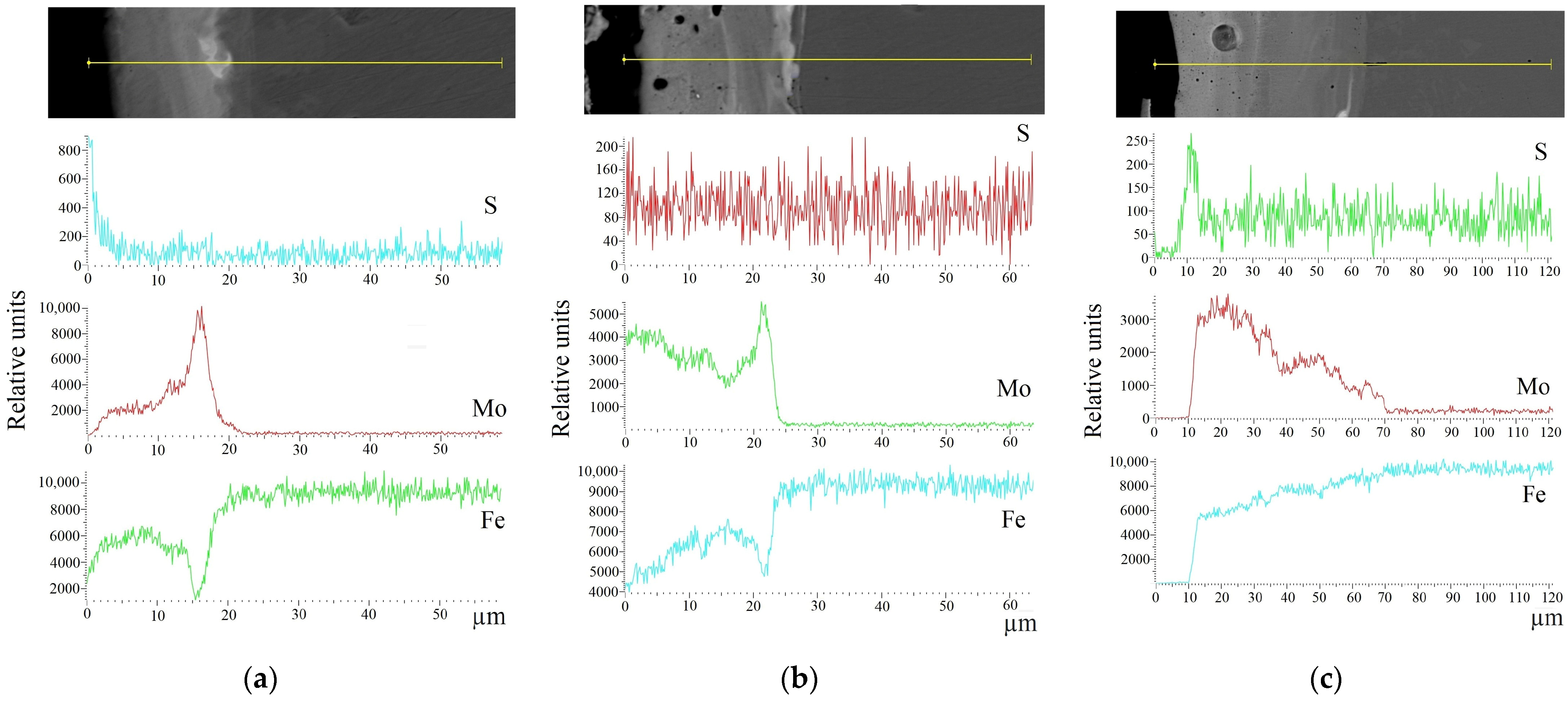
The SEM images were obtained with backscattered (reflected) electrons (BSE). The photos show the areas with clearly visible boundaries, where the colorings (shades) change depending on the atomic number of the chemical element. The analysis of the surface area containing the coating and the strip of substrate with a microstructure before deposition has shown that the obtained layers have a heterogeneous composition with different concentrations of elements (Figure 8). Thus, according to the diagram of the distribution of the elements over the area of the studied specimen (Figure 9), sulfur is concentrated on the surface, and molybdenum is evenly distributed in the coating.
The X-ray structural analysis of the coatings obtained by the ESA technology was carried out, and it was performed by a Mo-electrode with the use of a sulfur-containing paste. We have previously investigated that the phase composition of the coatings on C40 steel produced at Wp = 0.55 J is represented by a solid solution of BCC, the lattice period of which is close to that of ferrite, martensite, FCC solid solution, and intermetallic FeMo (σ-phase) [39]. With an increase in the discharge energy up to Wp = 3.4 J, in addition to solid solutions, up to 5% of molybdenum disulfide is formed. When the carbon content in the substrate material (C20 steel) is reduced, molybdenum disulfide is already formed at a discharge energy of 0.55 J. It was found to be about 3.77%. With an increase in Wp up to 3.4 J, ~8% of the MoS2 phase amount is on the surface, and ~5% thereof is at a distance of 15 μm from the surface. It can be assumed that the formation of MoS2 would have a positive effect on the tribotechnical properties of the modified surfaces.
For the design of the wear resistance of coatings, comparative tribotechnical tests were performed. The samples obtained by the two strategies of treatment and after molybdenum treatment by the ESA method were studied (Table 2). Figure 10 shows the nature of the change in the friction force of the specimens coated with Mo, Mo + S, and Mo + MoS2, which had been obtained by the ESA method at a discharge energy of 3.4 J on the AISI 321 steel.
In the specimen with molybdenum coating, the friction force from the beginning of the friction path to its completion had been increasing from 9 to 15 N at the loading of P = 20 N. In addition, the increase in the friction force had been accompanied by the appearance of fluctuations in the values after 2000 s of the test time. The force of friction as well as the amplitude of oscillations had been increasing from the beginning of the friction path to its end, which indicated the appearance of a tendency to stick (Figure 10a,b), resulting in the appearance of characteristic pits and cracks on the contact surface. With an increase in load to P = 40 N, the friction force F stabilized and was about 20 N. Therefore, with an increase in the load force, the friction force increases, but at the same time, the wear process stabilizes. The friction coefficients, respectively, at P = 20 N and P = 40 N correspond to the values μaverage = 0.6469 and μaverage = 0.4999 (Table 6).
The studies of the nature of the change in the friction force of the specimens with Mo + S coatings, wherein molybdenum disulfide has been formed during the ESA process, indicate that both the friction force and the friction coefficient in such specimens are significantly lower and correspond to the values of Fmax = 0.41 N and μaverage = 0.0156 at P = 20 N and Fmax = 0.43 N and μaverage = 0.0078 at P = 40 N (Table 6). It should be noted that the change in the friction force during the tests had been stable and amounted to about 0.3 N in both cases (Figure 10c,d).
For the Mo + MoS2 coatings, the nature of the change in the friction force over time indicates a stable wear process (Figure 10e,f). However, it can be noted that at P = 20 N, there is a slight increase of 0.4 N in the frictional force over time. Obviously, the coating takes longer to “run in” at low friction loads. The coefficients of friction, respectively, at P = 20 N and P = 40 N correspond to the values μaverage = 0.0630 and μaverage = 0.0510 (Table 6). The Mo + MoS2 coatings contribute to a significant reduction in friction force and wear intensity as compared to the molybdenum coatings.
Thus, a comparison of the tribotechnical properties of the coatings obtained using the two treatment strategies showed that the Mo-S coatings gave the best performance. The alloying process involves the application of a sulfur-containing paste to the surface to be treated, followed by electrospark alloying with a molybdenum electrode. It is obvious that the positive effect of Mo-S coatings on tribological parameters is associated with the formation of their specific structure (developed diffusion zone between the coating and the substrate, pore morphology and distribution, synthesis of molybdenum disulfide both on the surface and in the coating, etc.).

4. Conclusions

The electrospark coatings containing MoS2 were obtained according to the technologies proposed by the authors. The first technology consisted of previously applying molybdenum disulfide to the treated surface and alloying it with a molybdenum electrode (Mo + MoS2 coating). The second technology consisted of applying a paste comprising sulfur with a content of 33.3% to the treated surface and alloying it with a molybdenum electrode (Mo + S coating). The coating structure, phase composition, and tribological properties thereof were investigated. The main conclusions of this study can be summarized as follows:
The self-lubricating coatings applied by the ESA method have a complex structure consisting of an upper, loose, namely, non-hard layer, a strengthened “white” layer, a diffusion zone, and a substrate. The element analysis and cross-sectional hardness change have shown that the diffusion of the elements occurred at the interface between the coating and the substrate. This indicates that a strong interatomic bond has been formed between the coating and the substrate.
As the discharge energy increases, the number of pores in the white layer of the Mo + MoS2 coating increases, causing the shapes to change. The pores are distributed evenly and have rounded shapes. The X-ray structural analysis has established that the phase composition of the coating surface is represented by two solid solutions on Fe of a BCC crystal structure that differ in lattice period, i.e., an FCC solid solution, namely, austenite and MoS2. Molybdenum disulfide is identified as 26%–44%.
The phase composition of Mo + S coatings at the ESA discharge energy of 3.4 J is represented by BCC and FCC solid solutions on Fe, as well as MoS2, which is about 8% on the surface and ~5% at a distance of 15 μm from the surface.
The self-lubricating coatings demonstrate very good tribological properties as compared to the molybdenum ESA coatings. The friction force significantly diminishes, namely, by 10 times for the Mo+ MoS2 coating, by more than 40 times for the Mo + S coating at P = 20 N. In this case, the coefficients of friction for the Mo + MoS2 and Mo + S coatings are lowered by a factor of 10 and 40, respectively. At P = 40 N, μ is reduced by a factor of 64 for the Mo + S coating. The studies of the hardness and its distribution in the modified layers have shown that the coatings have approximately the same parameters, i.e., HV is about 1100 and thickness is ~60 μm. Obviously, the significant effect of the Mo + S coatings is related to the structural and phase states of the modified layers.

Author Contributions

Conceptualization, O.H. and V.T.; methodology, O.H. and N.T.; data analysis, O.H., N.T., T.M. and J.S.-C.; investigation, O.H., V.T., O.M., B.A.-C. and J.P.; writing—original draft preparation, O.H. and V.T.; writing—review and editing, O.H. and T.M.; visualization, O.H., O.M. and J.P.; project administration, O.H. and T.M. All authors have read and agreed to the published version of the manuscript.

Funding

Some of the results have been obtained within the research projects “Development of environmentally safe technologies for surface modification of power plant equipment parts using combined methods based on electrospark alloying” (State reg. No. 0124U000539), Sumy State University, funded by the Ministry of Education and Science of Ukraine, Verkhovna Rada Personal Scholarship of the Ukraine for Young Scientists–Doctor of Sciences, Oksana Haponova in 2023.

Institutional Review Board Statement

Not applicable.

Informed Consent Statement

Not applicable.

Data Availability Statement

The data presented in this study are available upon request from the corresponding author.

Conflicts of Interest

The authors declare no conflicts of interest.

References

  1. Roik, T.A.; Gavrysh, O.A.; Vitsiuk, I.I.; Kholiavko, V.V. Wear-Resistant Composites Produced from Tool Steel Waste for Contact Joints of High-Speed Printing Machines. Powder Metall. Met. Ceram. 2023, 62, 215–224. [Google Scholar] [CrossRef]
  2. Hlushkova, D.B.; Bagrov, V.A.; Volchuk, V.M.; Murzakhmetova, U.A. Influence of structure and phase composition on wear resistance of sparingly alloyed alloys. Funct. Mater. 2023, 30, 74–78. [Google Scholar] [CrossRef]
  3. Martsinkovsky, V.; Yurko, V.; Tarelnik, V.; Filonenko, Y. Designing radial sliding bearing equipped with hydrostatically suspended pads. Procedia Eng. 2012, 39, 157–167. [Google Scholar] [CrossRef]
  4. Tarelnyk, V.; Konoplianchenko, I.; Martsynkovskyy, V.; Zhukov, A.; Kurp, P. Comparative tribological tests for face impulse seals sliding surfaces formed by various methods. In Lecture Notes in Mechanical Engineering; Springer: Cham, Switzerland, 2019; pp. 382–391. [Google Scholar] [CrossRef]
  5. Martsinkovsky, V.; Yurko, V.; Tarelnik, V.; Filonenko, Y. Designing thrust sliding bearings of high bearing capacity. Procedia Eng. 2012, 39, 148–156. [Google Scholar] [CrossRef]
  6. Halchuk, T.N.; Povstyanoy, O.Y.; Bembenek, M.; Redko, R.G.; Chetverzhuk, T.I.; Polinkevych, R.M. Impact of technological system’s characteristics on the machining accuracy of bearing rings. J. Eng. Sci. 2023, 10, A22–A30. [Google Scholar] [CrossRef] [PubMed]
  7. Wasilczuk, M.; Wodtke, M. Experimental study on the feasibility of alternative materials for tilting pad thrust bearings operating in transition to mixed friction. Friction 2024, 12, 812–822. [Google Scholar] [CrossRef]
  8. Joseph, A.; Vijayan, A.S.; Shebeeb, M.C.; Akshay, K.S.; Mathew, K.P.J.; Sajith, V. A review on tailoring the corrosion and oxidation properties of MoS2-based coatings. J. Mater. Chem. A 2023, 7, 3172–3209. [Google Scholar] [CrossRef]
  9. Antoszewski, B.; Kurp, P. Effect of Surface Texture on the Sliding Pair Lubrication Efficiency. Lubricants 2022, 10, 80. [Google Scholar] [CrossRef]
  10. Bouti, S.; Antonova, M.N.; Hamouda, K.; Babichev, A.P.; Sayah, T. Structure and Mechanochemical Properties of the MoS2 Solid Lubricant Using Vibration Wave Treatment. Mater. Sci. 2018, 53, 739–749. [Google Scholar] [CrossRef]
  11. Martin, P.M. Handbook of Deposition Technologies for Films and Coatings; William Andrew Publishing: Boston, MA, USA, 2010; pp. 1–912. [Google Scholar]
  12. Seynstahl, A.; Köbrich, M.; Rosnitschek, T.; Göken, M.; Tremmel, S. Enhancing the lifetime and vacuum tribological performance of PVD-MoS2 coatings by nitrogen modification. Surf. Coat. Technol. 2024, 477, 130343. [Google Scholar] [CrossRef]
  13. Altuntepe, A.; Erkan, S.; Karadeniz, G. Large-scale synthesis of homogeneous WS2 films by physical vapor deposition. Eurasian J. Sci. Eng. Technol. 2023, 4, 36–41. [Google Scholar] [CrossRef]
  14. Bozheyev, F.; Friedrich, D.; Nie, M.; Rengachari, M.; Ellmer, K. Preparation of highly (001)-oriented photoactive tungsten diselenide (WSe2) films an amorphous solid-liquidcrystalline solid (aSLcS) rapid-crystallization process. Phys. Status Solidi A 2014, 211, 2013–2019. [Google Scholar] [CrossRef]
  15. Nozhenkov, M.V. The Ultra-Low Friction of Layer Structures. Mech. Eng. Res. 2013, 3, 73–89. [Google Scholar] [CrossRef]
  16. Poyraz, M.; Tunay, R.F. The effect of different sputtering parameters on coating thickness and hardness in MoS2 coated films with and without interlayer. Int. J. Surf. Sci. Eng. 2020, 14, 117–134. [Google Scholar] [CrossRef]
  17. Lu, X.; Sui, X.; Zhang, X.; Yan, Z.; Hao, J. Influence of V doping on the microstructure, chemical stability, mechanical and tribological properties of MoS2 coatings. Ind. Lubr. Tribol. 2024, 76, 29–40. [Google Scholar] [CrossRef]
  18. Torres, H.; Vuchkovb, T.; Slawikc, S.; Gachotd, C.; Prakashb, B.; Ripoll, M.R. Self-lubricating laser claddings for reducing friction and wear from room temperature to 600 °C. Wear 2018, 408–409, 22–33. [Google Scholar] [CrossRef]
  19. Yao, Y.H.; Wu, Y.C.; Zhang, Z.Y.; Zhu, H.; Hu, M.N.; Xu, K.; Liu, Y. Enhancement of frictional properties of Ni-MoS2 self-lubricating composite coatings by microgroove arrays. Appl. Surf. Sci. 2022, 605, 154635. [Google Scholar] [CrossRef]
  20. Li, S.; Zhao, X.; An, Y.; Liu, D.; Zhou, H.; Chen, J. YSZ/MoS2 self-lubricating coating fabricated by thermal spraying and hydrothermal reaction. Ceram. Int. 2018, 44, 17864–17872. [Google Scholar] [CrossRef]
  21. Liu, T.X.; Guo, C.A.; Lu, F.S.; Zhang, X.Y.; Zhang, L.; Wang, Z.J.; Xu, Z.Y.; Zhu, G.L. Influence of deposition voltage on tribological properties of W-WS2 coatings deposited by electrospark deposition. Chalcogenide Lett. 2023, 20, 741–749. [Google Scholar] [CrossRef]
  22. Yue, M.; Zhao, W.; Wang, S.; Li, J.; Zhu, C.; Jin, H.; Guo, C. Tribological properties of electrospark depositing Ni-WS2 self-lubricating coating. Chalcogenide Lett. 2021, 18, 557–564. [Google Scholar] [CrossRef]
  23. Wang, J.; Zhang, M.; Dai, S.; Zhu, L. Research Progress in Electrospark Deposition Coatings on Titanium Alloy Surfaces: A Short Review. Coatings 2023, 13, 1473. [Google Scholar] [CrossRef]
  24. Antoszewski, B.; Gaponova, O.P.; Tarelnyk, V.B.; Myslyvchenko, O.M.; Kurp, P.; Zhylenko, T.I.; Konoplianchenko, I. Assessment of Technological Capabilities for Forming Al-C-B System Coatings on Steel Surfaces by Electrospark Alloying Method. Materials 2021, 14, 739. [Google Scholar] [CrossRef] [PubMed]
  25. Yang, H.L.; Chen, X.M.; Chen, L.; Wang, Z.J.; Hou, G.C.; Guo, C.A.; Zhang, J. Influence of temperature on tribological behavior of AlCoCrFeNi coatings prepared by electrospark deposition. Dig. J. Nanomater. Biostructures 2023, 18, 145. [Google Scholar] [CrossRef]
  26. Tarelnyk, V.B.; Gaponova, O.P.; Loboda, V.B.; Konoplyanchenko, E.V.; Martsinkovskii, V.S.; Semirnenko, Y.I.; Tarelnyk, N.V.; Mikulina, M.A.; Sarzhanov, B.A. Improving Ecological Safety when Forming Wear-Resistant Coatings on the Surfaces of Rotation Body Parts of 12Kh18N10T Steel Using a Combined Technology Based on Electrospark Alloying. J. Surf. Eng. Appl. Electrochem. 2021, 2, 173–184. [Google Scholar] [CrossRef]
  27. Geng, C.X.; Zhang, H.X.; Li, X.J.; Geng, H.B. Elevated temperature tensile behaviour of 5183 aluminium alloy made by electrospark deposition additive manufacturing. Mater. Sci. Eng. A 2023, 868, 144746. [Google Scholar] [CrossRef]
  28. Myslyvchenko, O.M.; Gaponova, O.P.; Tarelnyk, V.B.; Krapivka, M.O. The Structure Formation and Hardness of High-Entropy Alloy Coatings Obtained by Electrospark Deposition. Powder Metall. Met. Ceram. 2020, 59, 201–208. [Google Scholar] [CrossRef]
  29. Cao, T.; Lei, S.; Zhang, M. The friction and wear behavior of Cu/Cu-MoS2 self-lubricating coating prepared by electrospark deposition. Surf. Coat. Technol. 2015, 270, 24–32. [Google Scholar] [CrossRef]
  30. Guo, C.; Kong, F.; Zhao, S.; Yan, X.; Yang, J.; Zhang, J. Performance of friction and wear of electrospark deposited ni-MoS2 self-lubricating coating. Chalcogenide Lett. 2019, 16, 309–315. [Google Scholar]
  31. Kiryukhantsev-Korneev, P.V.; Sheveyko, A.N.; Shvindina, N.V.; Levashov, E.A.; Shtansky, D.V. Comparative study of Ti-C-Ni-Al, Ti-C-Ni-Fe, and Ti-C-Ni-Al/Ti-C-Ni-Fe coatings produced by magnetron sputtering, electro-spark deposition, and a combined two-step process. Ceram. Int. 2018, 44, 7637–7646. [Google Scholar] [CrossRef]
  32. Tarelnyk, N. The Method of Eliminating Adhesion of Electrodes during Electrospark Alloying of Steel Parts of Equipment Subject to Radiation Exposure. Patent of Ukraine for Utility Model No. 155134: MPK (2006), B23P 6/00, B23H 1/00, C23C 28/00, 17 January 2024. Bull. No. 3. Available online: https://base.uipv.org/searchINV/search.php?action=viewdetails&IdClaim=287836 (accessed on 15 February 2024).
  33. Wang, J.M.; Liu, G.H.; Fang, Y.L.; Li, W.K. Marangoni effect in nonequilibrium multiphase system of material processing. Rev. Chem. Eng. 2016, 32, 551–585. [Google Scholar] [CrossRef]
  34. Tuo, Y.; Yang, Z.; Guo, Z.; Chen, Y.; Hao, J.; Zhao, Q.; Kang, Y.; Zhang, Y.; Zhao, Y. Pore structure optimization of MoS2/Al2O3 self-lubricating ceramic coating for improving corrosion resistance. Vacuum 2023, 207, 111687. [Google Scholar] [CrossRef]
  35. Borysov, Y.S.; Vihilianska, N.V.; Burlachenko, O.M.; Olevska, L.P.; Lopata, V.M. Analysis of modern experience in development of sealing coatings for parts of gas turbine engines (Review). Autom. Weld. 2022, 4, 41–49. (In Ukraine) [Google Scholar] [CrossRef]
  36. Boichyshyn, L.; Kovbuz, M.; Kulyk, Y.; Nosenko, V. Influence of the melt cooling rate of the structure on the alloyed iron based amorphous alloys with different form. Proc. Shevchenko Sci. Soc. Chem. Sci. 2015, 42, 101–108. [Google Scholar]
  37. Houserová, J.; Vřešťál, J.; Šob, M. Phase diagram calculations in the Co–Mo and Fe–Mo systems using first-principles results for the sigma phase. Calphad 2005, 29, 133–139. [Google Scholar] [CrossRef]
  38. Wang, W.; Du, M.; Zhang, X.; Luan, C.; Tian, Y. Preparation and Properties of Mo Coating on H13 Steel by Electro Spark Deposition Process. Materials 2021, 14, 3700. [Google Scholar] [CrossRef] [PubMed]
  39. Gaponova, O.P.; Antoszewski, B.; Tarelnyk, V.B.; Kurp, P.; Myslyvchenko, O.M.; Tarelnyk, N.V. Analysis of the Quality of Sulfomolybdenum Coatings Obtained by Electrospark Alloying Methods. Materials 2021, 14, 6332. [Google Scholar] [CrossRef] [PubMed]
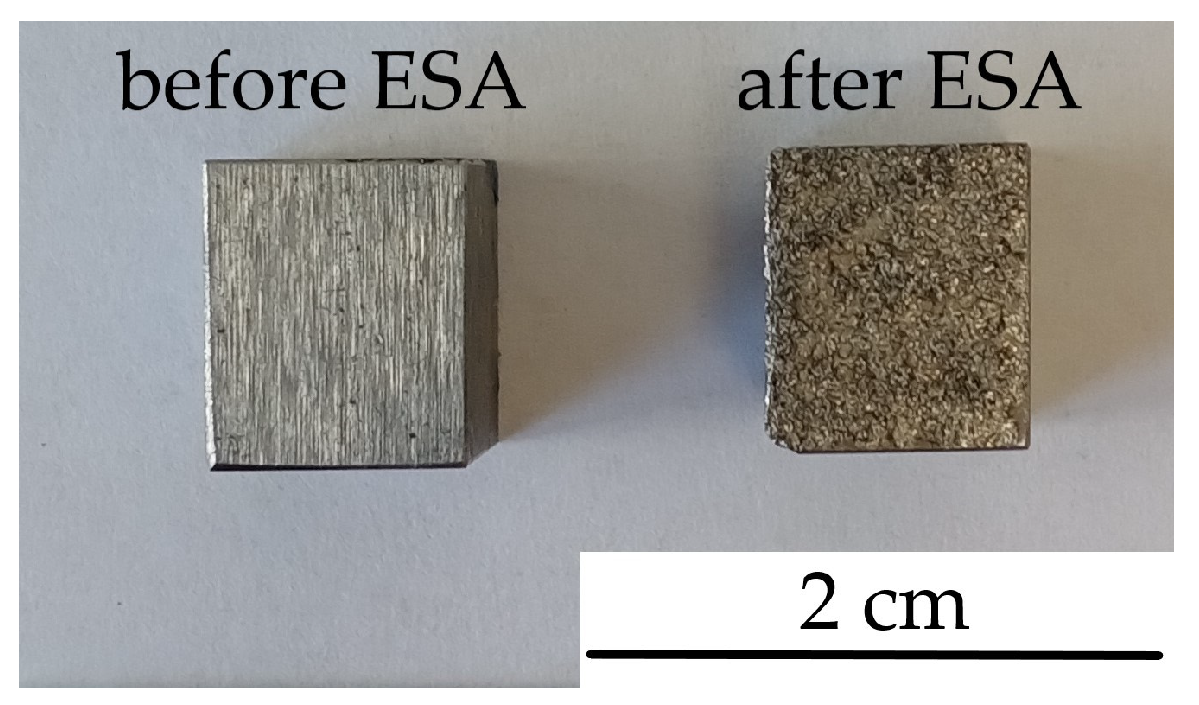
Figure 1. Samples before and after electrospark alloying.
Coatings 14 00563 g001
Figure 2. Schemes of strategies for treatment.
Coatings 14 00563 g002
Figure 3. Test scheme on the T-21 tribo-tester.
Coatings 14 00563 g003
Figure 4. Microstructures (a,b) and microhardness distribution (c) in the AISI 321 steel surface layer obtained by ESA technology, which is performed by a Mo-electrode with the preliminary application of MoS2 powder. The ESA process was performed at discharge energies (Wp): (a)—0.55 J; (b)—3.4 J; (c)—on the graph: 1—Wp = 0.55 J, 2—Wp = 3.4 J.
Coatings 14 00563 g004aCoatings 14 00563 g004b
Figure 5. Results of electron-microscopic studies of coatings obtained by ESA technology, which is performed by a Mo-electrode with preliminary application of MoS2 powder on the surface of AISI 321 steel. The ESA process was performed at discharge energies (Wp): (a)—0.55 J; (b)—3.4 J.
Coatings 14 00563 g005
Figure 6. Distribution of elements in coatings obtained by ESA technology, which is performed by a Mo-electrode with preliminary application of MoS2 powder on the surface of AISI 321 steel. The ESA process was performed at discharge energies (Wp): (a)—0.55 J; (b)—3.4 J.
Coatings 14 00563 g006
Figure 7. Diffractograms of the coatings obtained by the ESA technology, which is performed by a Mo-electrode with preliminary application of MoS2 powder on the surface of AISI 321 steel: A—surface, B—after polishing 15 μm. The ESA process was performed at discharge energies (Wp): (a)—0.55 J; (b)—3.4 J.
Coatings 14 00563 g007
Figure 8. Microstructures of coatings on C40 steel in an electron microscope at ESA discharge energies: (a)—0.13 J; (b)—0.55 J; (c)—3.4 J.
Coatings 14 00563 g008
Figure 9. Distribution of elements in coatings obtained by ESA technology, which is performed by a Mo-electrode with the use of a sulfur-containing paste, on C40 steel at the ESA discharge energies: (a)—0.13 J; (b)—0.55 J; and (c)—3.4 J.
Coatings 14 00563 g009
Figure 10. The nature of the change in the friction force T (N) of the steel ball over the surface of the test specimen: (a)—Mo coating, P = 20 N, (b)—Mo coating, P = 40 N, (c)—Mo + S coating, P = 20 N, (d)—Mo + S coating, P = 40 N, (e)—Mo+ MoS2 coating, P = 20 N, (f)—Mo+ MoS2 coating, P = 40 N.
Coatings 14 00563 g010
Table 1. Treatment modes of the Elytron–52A unit.
Discharge Energy (Wp), JCapacity of the
Capacitor Battery (C), µF
Output Voltage (U), VVibrator Oscillation
Frequency, Hz
0.133003550
0.553007550
3.4156010050
Table 2. Specimen series for tribotechnical studies.
Strategies
Treatment
SubstrateType of Processing
1AISI 321ESA-processed by Mo-electrode with the use of
MoS2-containing powder
2ESA-processed by Mo-electrode with the use of
S-containing paste
-ESA-processed by Mo-electrode
Table 3. Parameters of the coatings obtained by ESA technology performed by a Mo-electrode with preliminary application of MoS2 powder on the surface of AISI 321 steel.
Discharge Energy, Wp, JRoughness, Ra, μmStrengthened “White” Layer
HVh, μmContinuity, %
0.551.253420–3065
3.43.2112750–6080
Table 4. Parameters of the crystal lattices of the phases and the quantitative phase analysis of the coatings at the treated surface (A on Figure 7) obtained using the ESA technology by a Mo-electrode with preliminary MoS2 application to the AISI 321 steel.
Energy
Discharge, J
PhaseLattice Period,
a, nm
Phase Content, % (wt.)
0.55BCC1 solid solution on α-Fe2.870014.0
BCC2 solid solution on α-Fe2.890015.0
FCC solid solution on γ-Fe3.590025.0
MoS2a = 3.1612
c = 12.2985
46.0
3.4BCC1 solid solution on α-Fe2.870024.0
BCC2 solid solution on α-Fe2.890025.0
FCC solid solution on γ-Fe3.650024.0
MoS2a = 3.1612
c = 12.2985
27.0
Table 5. Parameters of the coatings obtained by the ESA with Mo-electrode using S-containing paste.
Discharge
Energy,
Wp, J
Roughness,
Ra, μm
Layer of Low
Microhardness
Strengthened “White Layer”
HVh, μmHVh, μmContinuity, %
C20 Steel
0.130.6111.220514.72065
0.551.9136.830715.03075
3.45.5166.6401059.65090
C40 Steel
0.130.8132.010547.42575
0.552.0167.020783.24090
3.45.7204.0301073.17095
AISI 321 Steel
0.130.9146.410651.42080
0.552.2173.215882.73090
3.46.2240.3201137.355Up to 100
Table 6. The tribological properties of the tested coatings.
Sample SeriesSubstrateLoad,
P, N
Maximum
Frictional Force,
Fmax, N
Friction Force
Average Value
Faverage, N
Average Coefficient of Friction, μaverage
MoAISI 321 steel2016.7912.9380.6469 ± 0.0257
4023.0619.970.4999 ± 0.0074
Mo + S200.410.310.0156 ± 0.0059
400.430.310.0078 ± 0.0001
Mo + MoS2201.831.200.0630 ± 0.0001
402.512.000.0510 ± 0.0031
Disclaimer/Publisher’s Note: The statements, opinions and data contained in all publications are solely those of the individual author(s) and contributor(s) and not of MDPI and/or the editor(s). MDPI and/or the editor(s) disclaim responsibility for any injury to people or property resulting from any ideas, methods, instructions or products referred to in the content.